
Distributor Timing Curves


Distributor Timing Curves
Does anybody know the effects of the specific differences in the timing curves of different distributors for SA/FBs?
I have a 1980 (electronic ignition), and have a spare 1983 distributor sitting around.
Is one of these better than the other if I were to go with a MSD 6A setup?
By pouring over the FSMs I've found that:
Centripetal:
1980: 10 deg by 1500 rpm.
1983: 10 deg by 1750 rpm.
Vacuum:
1980: L&T 7.5 deg by 400 mmHg
1983: L: 4.5 deg by 190 mmHg, T: 15 deg by 400 mmHg
Cheers,
Kam


I'd use the 83. At very light cruise you may see at max 25 degrees of compensation, they can take much more than that under those conditions. Up your timing some more by ~5 degrees and you'd get a healthy increase in power safely.


Joined: Mar 2001
Posts: 31,833
Likes: 3,232
From: https://www2.mazda.com/en/100th/
to really answer that question you need to try some different timings on you car and see what it likes.
generally with the 12A the later the engine the more advance it has, but the higher the RPM where it comes in.
i find that the total timing is ok, but it can come in at a lower rpm
generally with the 12A the later the engine the more advance it has, but the higher the RPM where it comes in.
i find that the total timing is ok, but it can come in at a lower rpm
Joined: Jun 2008
Posts: 8,376
Likes: 28
From: Chino Hills, CA
From a wiring standpoint the 80 dizzy is easier - pickups are equipped with shielded cables that deliver directly over to the left strut tower. Reluctor output is plug and play.
With the later dizzies you have to fabricate that cable and work up a connection set that replaces the ignitors & their connectors, like the "gutted J-109" trick I've seen here.
I'd also look over which unit is in better mechanical shape; they do wear out over time, and precise timing needs to have bushings, end play, and the advance parts within wear specs.
Thank you all for the informative replies.
I will check over which is in better condition.
I guess to confirm, I could always install both and use a timing light to see how much advance I get at various rpms?
As of now I will go with the distributor that seems in better condition, which strangely I think it the 80.
Thanks all again,
Kam
I will check over which is in better condition.
I guess to confirm, I could always install both and use a timing light to see how much advance I get at various rpms?
As of now I will go with the distributor that seems in better condition, which strangely I think it the 80.
Thanks all again,
Kam
talking head
Joined: Apr 2008
Posts: 2,775
Likes: 15
From: Perth, WA, OZ
i hope you have gathered that the numbers in the FSM are from a distributor graphing machine and as such,, what happens at the crank is doubled
ie 1750 rpm at dizzy is 3500 rpm on the crank
and 10 at the dizzy is 20 degrees on the crank
ie 1750 rpm at dizzy is 3500 rpm on the crank
and 10 at the dizzy is 20 degrees on the crank
Note that the trigger signal from the FB dizzy is different from that of the 80 dizzy. So switching
to the one from the other may require the dizzy signals to be reversed where they terminate at
your ignition box. It will drive you crazy until you realize it. I discovered this when I was
developing the replacement ignition in my SA. See the TFIDFIS link in my sig for the gory details.
to the one from the other may require the dizzy signals to be reversed where they terminate at
your ignition box. It will drive you crazy until you realize it. I discovered this when I was
developing the replacement ignition in my SA. See the TFIDFIS link in my sig for the gory details.
Trending Topics
Joined: Jun 2008
Posts: 8,376
Likes: 28
From: Chino Hills, CA
I was just looking at the output pulse from my spare 80 dizzy with an o-scope on Saturday, as part of an ongoing project.
It's essentially a single cycle AC pulse for each trigger. With proper polarity (scope ground to the center pin on the dizzy connector) the pulse first goes positive, then goes negative. The zero-crossing point on the way down happens as the reluctor tooth lines up with the coil core. It's not a sine wave; moderately ramped rise, very abrupt reversal, longer slope back to zero. Due to the shape of the reluctor (star wheel) teeth, which I think is different on the 81+ units.
Voltage of the pulse is a function of RPM; low-speed hand-spinning of the dizzy produced anywhere from around 1.5-2V p-p up to maybe 6.
Bumpstart; I did not realize that, but now know. Thank you.
T G Farrell; I have read through part of your thread. I will see what I can do with the two distributors to comebine the ease of wiring of the 80 with the improved reluctor design of the 81+.
DivinDriver; correct me if I am wrong, but are you saying that the difference in the shape of the reluctor rings leads to a different wave being produced? positive first for 80s and negative first for 81+?
Joined: Jun 2008
Posts: 8,376
Likes: 28
From: Chino Hills, CA
I don't have an 81 to play with, but the shape would not reverse the polarity - - that's driven by the direction the reluctor moves in relation to the pickup oil and the polarity of the magnet in the pickup assembly, & the way the pickup is wound. (Fleming's "Right-hand Rule")

The shape of the reluctor dictates the shape of the waveform to some degree; how fast it rises and falls, much like the shape of a cam dictates the movement of a lifter on a boinger.
Since it's an AC waveform and not referenced to ground, you can invert the polarity by reversing the leads from the pickup.
talking head
Joined: Apr 2008
Posts: 2,775
Likes: 15
From: Perth, WA, OZ
the reluctor ring is turned around on the later dizzy.. the later dizzy uses j109
the early dizzy uses j105
i surmise the later dizzy has the wheel arranged to suit the correct ( positive falling to negative ) trigger edge for a j109
( and , it seems many popular inductive trigger bosch igniters )
but in saying that,, then the early j105 instead is configured to see a zero crossing on the way up.. and that is why the trigger wheel bias is opposite
just a theory but it does fully explain why when wiring up early dizzy to late ( and bosch ) igniters,, you must swap the trigger pair polarity around
Christ...mas. You guys amaze! I have, with regret, virtually NO idea what you are talking about. And hope never to HAVE to know. But sure nice to have this forum - and you guys - to support it.
I will just slip back now and try to learn from Masters...
Stu Aull
80GS (working Dizzy for the moment)
Alaska
I will just slip back now and try to learn from Masters...
Stu Aull
80GS (working Dizzy for the moment)
Alaska
I was just looking at the output pulse from my spare 80 dizzy with an o-scope on Saturday, as part of an ongoing project.
It's essentially a single cycle AC pulse for each trigger. With proper polarity (scope ground to the center pin on the dizzy connector) the pulse first goes positive, then goes negative. The zero-crossing point on the way down happens as the reluctor tooth lines up with the coil core. It's not a sine wave; moderately ramped rise, very abrupt reversal, longer slope back to zero. Due to the shape of the reluctor (star wheel) teeth, which I think is different on the 81+ units.
Voltage of the pulse is a function of RPM; low-speed hand-spinning of the dizzy produced anywhere from around 1.5-2V p-p up to maybe 6.
It's essentially a single cycle AC pulse for each trigger. With proper polarity (scope ground to the center pin on the dizzy connector) the pulse first goes positive, then goes negative. The zero-crossing point on the way down happens as the reluctor tooth lines up with the coil core. It's not a sine wave; moderately ramped rise, very abrupt reversal, longer slope back to zero. Due to the shape of the reluctor (star wheel) teeth, which I think is different on the 81+ units.
Voltage of the pulse is a function of RPM; low-speed hand-spinning of the dizzy produced anywhere from around 1.5-2V p-p up to maybe 6.
explain this to folks I bet (pic == 1000 words and all).
I pulled up this article; http://www.zublin.com/msd/msd6a_02.pdf
On page 7 they show that a MSD 6a is triggered by using edge of the wave, they also show that the dropping edge's timing changed with rpm.
Could this be why an SA distributor wired reversed (to have correct polarity) doesn't run as well as a FB dizzy wired normally? It is essentially using the "wrong side" of the wave as a trigger?
Joined: Jun 2008
Posts: 8,376
Likes: 28
From: Chino Hills, CA
Nothing wrong with the way an SA's ignition operates, so long as it's in good repair.
So long as the ignitor is designed for it, triggering on the midpoint leading or trailing edge is pretty much equivalent.
That report discusses how the MSD works & where it triggers off of (leading edge of the midsignal rising lobe.
To get that from an 80 dizzy, just wire it with the pickup coil leads reversed. The pulse will go negative, then sharply positive, before dropping back to zero.
Yep, similiar issue with HEI modules as well. I will say the FB dizzy wave form works better than
the SA waveform with HEI modules. I have first hand experience of that. My theory is the shape
of the reluctor wheel is better in the FB dizzy.
the SA waveform with HEI modules. I have first hand experience of that. My theory is the shape
of the reluctor wheel is better in the FB dizzy.
I guess the issue is whether a reversed SA signal is the same as a FB signal.
It seems that from the graph in the PDF it's not and that as mentioned if I'm going HEI or MSD 6a it would probably be best if I went with the FB dizzy if it is an option.
Now if only it warmed up outside and I could start working on the car again!!!
It seems that from the graph in the PDF it's not and that as mentioned if I'm going HEI or MSD 6a it would probably be best if I went with the FB dizzy if it is an option.
Now if only it warmed up outside and I could start working on the car again!!!
Joined: Jun 2008
Posts: 8,376
Likes: 28
From: Chino Hills, CA
I guess the issue is whether a reversed SA signal is the same as a FB signal.
It seems that from the graph in the PDF it's not and that as mentioned if I'm going HEI or MSD 6a it would probably be best if I went with the FB dizzy if it is an option.
Now if only it warmed up outside and I could start working on the car again!!!
It seems that from the graph in the PDF it's not and that as mentioned if I'm going HEI or MSD 6a it would probably be best if I went with the FB dizzy if it is an option.
Now if only it warmed up outside and I could start working on the car again!!!
Here's a lame cellphone video of the SA pickup waveform (click to play):
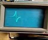
How does that look to differ substantially from the hypothetical in the PDF, outside of being inverted (which with an AC waveform means nothing except lead position)?
The report stated that the MSD fires at roughly 0.3v on the leading edge of the positive pulse.
The pulses shown (generated while I spun the dizzy one-handed with a string, holding the phone with the other) were about 4v peak to peak, and if anything sharper and more defined than the example traces drawn in the report.
By reversing the polarity by swapping the two leads from the pickup, it would work just fine.
I've got around 43 years experience working with signals electronics.
I don't know the requirements of the HEI ignitors, but based on that report, your SA dizzy would work fine with the MSD as described. So too would the FB in all likelihood.
The PDF didn't reference the FB or SA dizzies as far as I could see. It showed only a hypothetical waveform.
Here's a lame cellphone video of the SA pickup waveform (click to play):
How does that look to differ substantially from the hypothetical in the PDF, outside of being inverted (which with an AC waveform means nothing except lead position)?
The report stated that the MSD fires at roughly 0.3v on the leading edge of the positive pulse.
The pulses shown (generated while I spun the dizzy one-handed with a string, holding the phone with the other) were about 4v peak to peak, and if anything sharper and more defined than the example traces drawn in the report.
By reversing the polarity by swapping the two leads from the pickup, it would work just fine.
I've got around 43 years experience working with signals electronics.
I don't know the requirements of the HEI ignitors, but based on that report, your SA dizzy would work fine with the MSD as described. So too would the FB in all likelihood.
Pending the condition of my SA distributor I will try both out and compare.
Cheers!
Joined: Jun 2008
Posts: 8,376
Likes: 28
From: Chino Hills, CA


Thread
Thread Starter
Forum
Replies
Last Post