
GT35R Here I come! :D


Thread Starter
Rotary Enthusiast
Joined: Feb 2001
Posts: 1,094
Likes: 0
From: Orange County, CA
Well I thought I would have the car ready for Seven Stock, but I got busy with work and some other stuff; I didn't even make it myself...
I also decided that I wasn't comfortable with the silicone tubing for the wastegate that came with the Blitz boost controller. So I replaced them with some AN fittings and SS lines, and then had fun routing and mounting them so they don't rub or move.
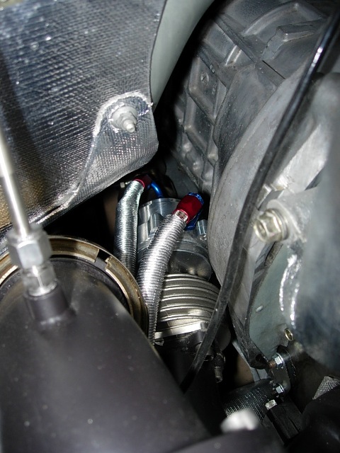
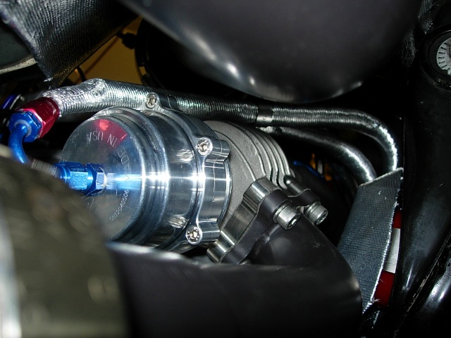
Lastly I installed an oil reservoir (right behind the BOV) for 2 cycle oil that will be injected via the OMP:
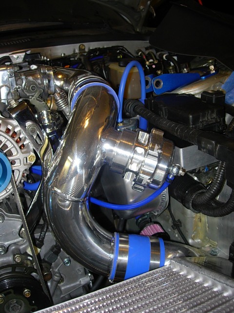
Everything is done in the engine bay, electrical routing to the cabin, etc. 'All' I have to do now is to mount the battery in the bin, mount some of the electrical stuff in the cabin and wire everything up.

I also decided that I wasn't comfortable with the silicone tubing for the wastegate that came with the Blitz boost controller. So I replaced them with some AN fittings and SS lines, and then had fun routing and mounting them so they don't rub or move.
Lastly I installed an oil reservoir (right behind the BOV) for 2 cycle oil that will be injected via the OMP:
Everything is done in the engine bay, electrical routing to the cabin, etc. 'All' I have to do now is to mount the battery in the bin, mount some of the electrical stuff in the cabin and wire everything up.
Last edited by atihun; Nov 1, 2006 at 09:53 AM.

Darkside FD
Joined: Jan 2004
Posts: 1,175
Likes: 0
From: AZ
Originally Posted by atihun
Everything looks great. Soooo much time put into this! You are a very patient man! But the result is excellent work.
7 Rx-7s since 1980
Joined: Mar 2004
Posts: 438
Likes: 1
From: oHIo
Awesome work!
One observation...the wires come out of the O2 sensor...that sharp 90degree off the DP might be a little problematic. The DP will move with the engine and that sharp 90degree might stress that area. Some of that heat tubing in a 90 degree will it from being that drastic on the turn for the wires.
Also, the wires as they come up the DP....you might want to put them into a small sleeve of shield them a little bit.
Did you use RS's Oil metering pump?
How about a nice wide shot of the engine bay with everything in it's place since the last changes? Ahhhh.....
Tony
Thread Starter
Rotary Enthusiast
Joined: Feb 2001
Posts: 1,094
Likes: 0
From: Orange County, CA
Thanks! I am finally getting really excited to get it started! 
---How and where did you connect these lines to the vacuum/pressure source? Do you have a couple of quick picks of that end?
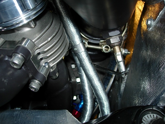
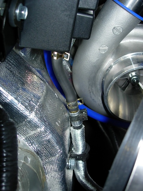
I ran the stainless steel line close to where they connect and for each line I used a brass male to male barb fitting. At the end of the stainless line, I used a thin piece of aluminum to wrap around the hose so it doesnt fray, and then used a fuel hose clamp to clamp it to the fitting. Then from the other end of the fitting to the boost controller I used thick walled walled viton tubing. I'll try to get a close-up picture of it.
---One observation...the wires come out of the O2 sensor...that sharp 90degree off the DP might be a little problematic. The DP will move with the engine and that sharp 90degree might stress that area. Some of that heat tubing in a 90 degree will it from being that drastic on the turn for the wires.
That's the stock O2 sensor so it doesn't really matter! But there's slack on the line, it just turns straight up.
---Also, the wires as they come up the DP....you might want to put them into a small sleeve of shield them a little bit.
Isn't the stock tubing around the wire a heat tubing? If not, I'll try to find some small tubing for it.
---Did you use RS's Oil metering pump?
What's the RS OMP? I used the Rotary Aviation adapter and the stock OMP.
---How and where did you connect these lines to the vacuum/pressure source? Do you have a couple of quick picks of that end?
I ran the stainless steel line close to where they connect and for each line I used a brass male to male barb fitting. At the end of the stainless line, I used a thin piece of aluminum to wrap around the hose so it doesnt fray, and then used a fuel hose clamp to clamp it to the fitting. Then from the other end of the fitting to the boost controller I used thick walled walled viton tubing. I'll try to get a close-up picture of it.
---One observation...the wires come out of the O2 sensor...that sharp 90degree off the DP might be a little problematic. The DP will move with the engine and that sharp 90degree might stress that area. Some of that heat tubing in a 90 degree will it from being that drastic on the turn for the wires.
That's the stock O2 sensor so it doesn't really matter!
But there's slack on the line, it just turns straight up. ---Also, the wires as they come up the DP....you might want to put them into a small sleeve of shield them a little bit.
Isn't the stock tubing around the wire a heat tubing? If not, I'll try to find some small tubing for it.
---Did you use RS's Oil metering pump?
What's the RS OMP? I used the Rotary Aviation adapter and the stock OMP.


Originally Posted by atihun
Attila,
Watch those wastegate mounting cap head bolts like a hawk! They WILL come loose if you track your car. Ask me how I know. I switched mine to a stud and nut arrangement with Nordlock washers. Some have gone so far as to drill and wire tie the bolts to stop them from loosening ...AND FALLING OUT.
http://www.negative-camber.org/crispyrx7/gt35rpage4.htm
(bottom of the page)
BTW Wise idea for the SS lines to the wastegate...mind if I follow your lead?
FWIW,
Crispy
Thread Starter
Rotary Enthusiast
Joined: Feb 2001
Posts: 1,094
Likes: 0
From: Orange County, CA
Thanks for the heads up Crispy!
I couldn't tell if those were lock washers that you used. Do you think that since I used lock washers it would help? Or should I just replace them now... ahhh more work!!!!
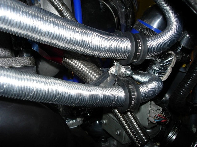
The SS lines seem like the best way to go for the wastegate. I still used a heat shield tubing aroung them as well as they are about 1/2 inches away from the manifold.
I couldn't tell if those were lock washers that you used. Do you think that since I used lock washers it would help? Or should I just replace them now... ahhh more work!!!!
The SS lines seem like the best way to go for the wastegate. I still used a heat shield tubing aroung them as well as they are about 1/2 inches away from the manifold.
Originally Posted by atihun
Thanks for the heads up Crispy!
I couldn't tell if those were lock washers that you used. Do you think that since I used lock washers it would help? Or should I just replace them now... ahhh more work!!!!
The SS lines seem like the best way to go for the wastegate. I still used a heat shield tubing aroung them as well as they are about 1/2 inches away from the manifold.
Crispy
Thread Starter
Rotary Enthusiast
Joined: Feb 2001
Posts: 1,094
Likes: 0
From: Orange County, CA
Crispy,
Do you think that I can use the Nord locks with the allen bolts I have so I don't have to take everything apart?

Do you think that I can use the Nord locks with the allen bolts I have so I don't have to take everything apart?
Last edited by atihun; Nov 1, 2006 at 08:32 PM.
7 Rx-7s since 1980
Joined: Mar 2004
Posts: 438
Likes: 1
From: oHIo
Nice idea on the Nordlocks, guys. Thanks. While my wastegate uses a v-band clamp on both ends (TurboSmart) I have had that problem with the turbo and other hot/cold areas.
For those that are thinking about running the WG lines in AN-06...both those lines fit very nicely into a 1" sewn fabric sleeve of heat shielding. Pre-made, of course. Might save in the areas where both lines are run in parallel. Examing lines in the shielding versus exposed to the heat of the DP/manifold, I found the exposed lines show more brittleness. The ones in the heat shielding looked and felt like they were brand new. This is after about 7K miles through a summer and half of hard running.
Again, I hear of or learn something new in about every page of this thread. Or at least have those lovely pictures to look at. Thanks!
Tony
Thread Starter
Rotary Enthusiast
Joined: Feb 2001
Posts: 1,094
Likes: 0
From: Orange County, CA
Crispy, where did you buy your locks from?
Also, I used -4 lines and fittings as that corresponded to the hole size on the 6mm tubing that came with the boost controller. I hope it's large enough!
Cozmo, here's a picture of the end of the line to the boost controller. You can see the thin aluminum I added to the end of the line and the viton tubing.
Tony, here's the 'money shot'... literally (just like in pr0n!)
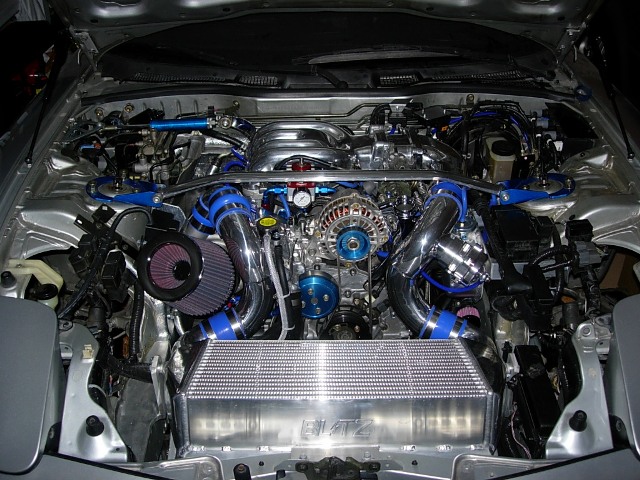
Looks like I have to modify the undertray a bit too...
Also, I used -4 lines and fittings as that corresponded to the hole size on the 6mm tubing that came with the boost controller. I hope it's large enough!
Cozmo, here's a picture of the end of the line to the boost controller. You can see the thin aluminum I added to the end of the line and the viton tubing.
Tony, here's the 'money shot'... literally
(just like in pr0n!)Looks like I have to modify the undertray a bit too...
7 Rx-7s since 1980
Joined: Mar 2004
Posts: 438
Likes: 1
From: oHIo
Ahhhh!
Side note, have you ever thought about doing a triangular cover over the ABS area and power steering/brake areas? From the shock tower to the firewall. I have been thinking about that. Punch in a couple of louvered vents but mainly to have it hide those areas.
Are you driving the car now?! You should setup a webcam and let us all just subcribe to drool over the car when we want!
Tony
Originally Posted by atihun
Crispy, where did you buy your locks from?
Very nice folks, they now their hardware, and were willing to sell in any quantity I wanted although I think the only have "small quantity" bags of the nordlocks - never hurts to have a few extra though.
HTH,
Crispy

Rotary Freak
Joined: Nov 2001
Posts: 2,715
Likes: 1
From: trinidad and tobago
Atihun , were there any problems when you welded your rad ?, I'm planning on modifying mine (if I dont get it sold) to make it a 3 pass for better cooling , since I'm going to upgrading (?) to a new 4" thick FMIC , I am a bit worried about the brazing process used to make these rads , I hope tig welding doesnt cause any leaks where the tube sheet and tank meets.

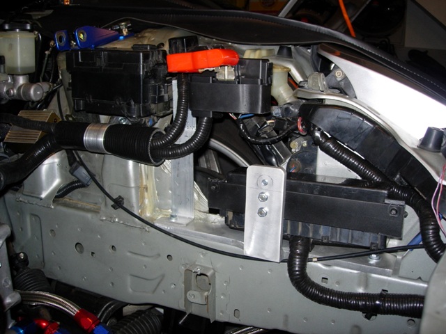
Atilla,
How did you make the aluminum bracket you used for the long fuse box? I'm horribly new to metal working. Is that something you just cut out of a piece, or did you cut two pieces and weld them together?
- Andy
How did you make the aluminum bracket you used for the long fuse box? I'm horribly new to metal working. Is that something you just cut out of a piece, or did you cut two pieces and weld them together?
- Andy
Originally Posted by atihun
Here's the relocation of the fuseboxes:
Thread Starter
Rotary Enthusiast
Joined: Feb 2001
Posts: 1,094
Likes: 0
From: Orange County, CA
Marcell,
The piping for the radiator was tig welded; I did some of the mig welding but the pipes and tubing are too thin to be mig welded. I'm not sure about any leaks yet!
Matt,
The heat wrapping was Thermotec and you can find it at summitracing.com.
Andy,
The bracket for the long fuesbox was just one piece of 1/8 x 1 1/2 inch aluminum cut to the lenght of the plastic mounting ends of the fuse box. I then held the piece of aluminum with two bolts to my IC mount, and then held the bracket at the ends to the plastic of the fusebox. It's sturdy and out of the way.
By the way, the front and undertray is all on and the car is finally on the ground after over a year and a half.
I will post some pics and a vid of the startup; probably next weekend!
Thanks everyone for the input!
Thread Starter
Rotary Enthusiast
Joined: Feb 2001
Posts: 1,094
Likes: 0
From: Orange County, CA
Originally Posted by jacobcartmill
i'm still waiting to see that gauge cluster lit up...
Here's the last of the list to do:
Install Battery in Passanger Bin
Run Lines
Add Breaker
Connect all interior wiring
PowerFC
Datalogit
Techedge
Install Glovebox Items
Datalogit
Techedge
Route Wiring for 02 sensor (both)
Install Injector driver inside
Setup components for idle
Fill Systems
Wire all components for Defi Guages
Coolant
Sensors for EGT, Oil Pressure, Coolant, Fuel Pressure
Wiring for controller
Oil
Wire up the Battery - Charge seperately prior to install
Check Datalogit and Techedge for functionality
Install Clutch Switch and shifter assembly
Check PFC Readings
Verify Settings and voltages
Check TPS
Prime Systems
Fuel - add 3 gallons new
Check for leaks
Check fuel pressure
Oil system - crank without fuel