When you click on links to various merchants on this site and make a purchase, this can result in this site earning a commission. Affiliate programs and affiliations include, but are not limited to, the eBay Partner Network.
For many years I have been making big and small modification on my FD and from time to time checking this forum for information and inspiration.
There are no real targets for the build except to have fun and learning through the process.
Some of the modds made:
- Custom V-mount and intake
- Haltech Nexus R5
- Custom Single turbo Garrett G25-660 Tial MVR wastegate
- Xcessive lower intake and Bosch 82mm DBW
- 2x980 + 4x1300 CC bosch injectors. Aeromotive A-1000
- IGN1a coils
I choose the G25-660 because of availability and size, this was the only G-series available when i converted to single.
But now there are now a bigger range of G-series availble easy to change up to.
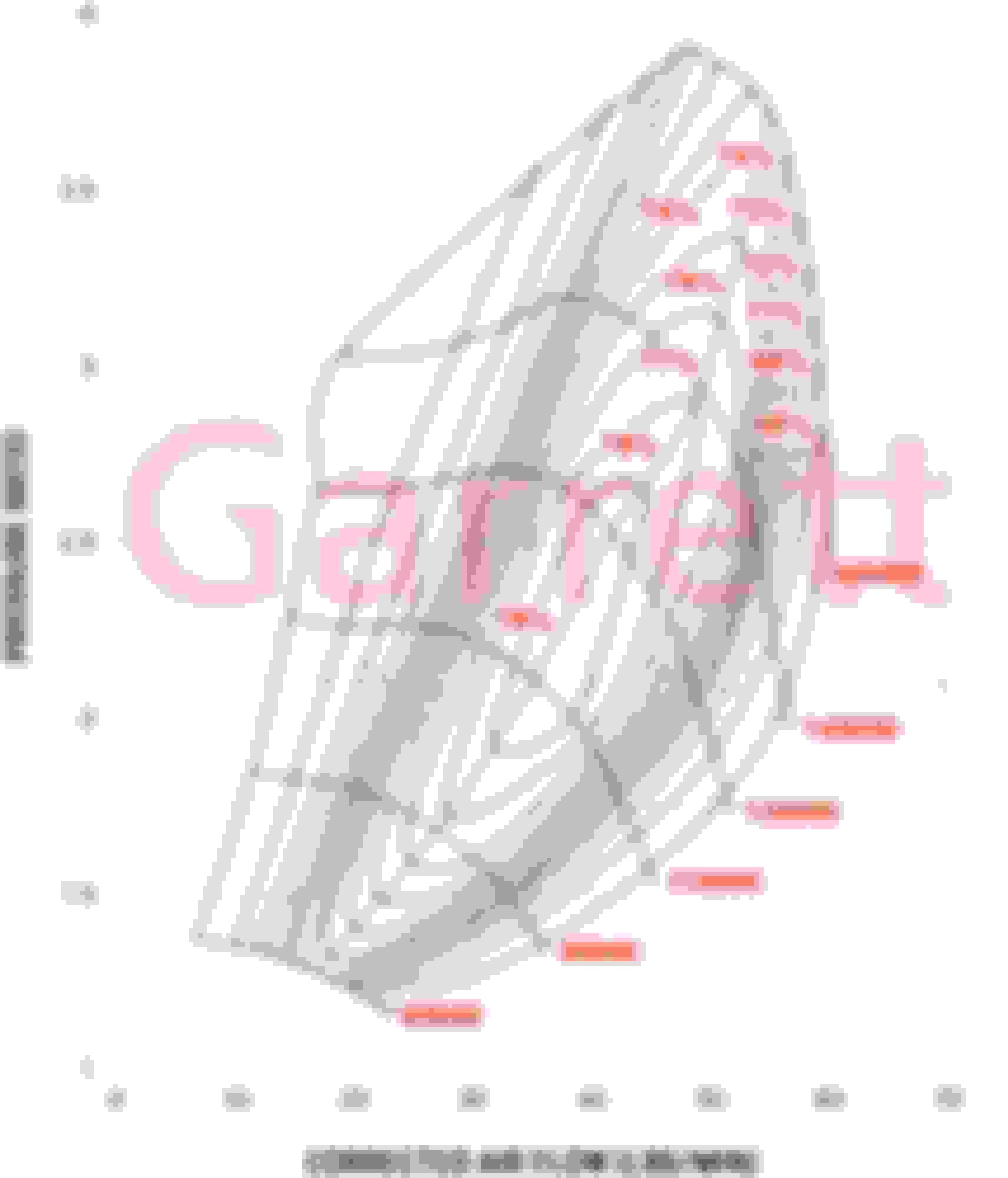
Below I have attached a screenshot from a street pull and it would be good to here thoughts/comments on the numbers, what is good and what is bad?
Im also running E85 and I wonder what the extra amount of mass that might bring affect the turbine flow?
Honestly, it looks like you're on the right track. Only running the car to 6500rpms is really gonna limit the feeling of the car. If you can get a bigger exhaust housing, I think that would be a good step seeing how fast your EMAP is rising towards the top.
Is the car dyno tuned?
How do you like the Nexus so far?
Also, if you are planning on running more boost, I would recommend more aluminum piping to cut down on silicon boots. Pressurize the intake system and I think you'll be surprised to see how much those boots will expand.
Overall, great work!
been looking at a G25-660 for a while now, but waiting … because back in Feb. Garrett finally listed the divided T4 0.92 housing for it again, then kept saying it was coming, then said no later than June or July, but recently deleted it off the housing listing again. Have no idea what the issue is with that. Was about to ask ATP Turbo for a status update when I noticed they took it down again.
The low rpm spool has got to be something; pretty much better MOI than an EFR7163 with EFR7670 turbine flow by my estimation. Have you got a more defined boost vs rpm log?
which you can only get so much out of it since the compressor peak is just at 60 lbs/min at ~2.55 PR tapering off above and below. You didn’t state which turbine housing either?
Honestly, it looks like you're on the right track. Only running the car to 6500rpms is really gonna limit the feeling of the car. If you can get a bigger exhaust housing, I think that would be a good step seeing how fast your EMAP is rising towards the top.
Is the car dyno tuned?
How do you like the Nexus so far?
Also, if you are planning on running more boost, I would recommend more aluminum piping to cut down on silicon boots. Pressurize the intake system and I think you'll be surprised to see how much those boots will expand.
Overall, great work!
No the car is not tuned fully unfortunatly, I might be able to do a power pull on a dyno quite soon though,
The Nexus is a dream compared to the my old haltech PS2000, Much more complex but whit many of the function that i wanted to test.
I�m very happy with the PDM funtionallity, the wiring was much simpler.
Thanks for the tips of the silicon boots! the intake will be changed a bit soon, the DBW adapter is just a 3d printed one.
But I have run 14-16psi as whit it so it's quite durable.
I might increase the boost to around 20psi in the future but for that i need the final DBW adapter.
been looking at a G25-660 for a while now, but waiting … because back in Feb. Garrett finally listed the divided T4 0.92 housing for it again, then kept saying it was coming, then said no later than June or July, but recently deleted it off the housing listing again. Have no idea what the issue is with that. Was about to ask ATP Turbo for a status update when I noticed they took it down again.
The low rpm spool has got to be something; pretty much better MOI than an EFR7163 with EFR7670 turbine flow by my estimation. Have you got a more defined boost vs rpm log?
which you can only get so much out of it since the compressor peak is just at 60 lbs/min at ~2.55 PR tapering off above and below. You didn’t state which turbine housing either?
.
.
Yes the boost response is quite good!
I have the 0,92 Vband housing
I will ad more from some logs below.
I have also activated the estimated Ariflow and fuel flow in the ECUs logs shouldn�t it be possible to use that to plot the compressor map. 2nd to 3 gear pull. The traction control Cuts har in second.
WOW . That's some comprehensive information ! Excellent stuff!
If I'm reading it(log 312) right at 6500engine rpm that's putting peak on compressor map at around 132,000rpm ,2.1PR, 50lbs/min ,71% efficiency ?
With boost at 12.5psi, pre IC at 16.2psi and EMAP at 23psi ?
I have the G30-660 on my Renesis . Initially had the 1.01 AR on it but will be trialing the 0.83 shortly , which is supposedly very close to what you have. Will be interesting to make some comparisons.
having comprehensive data is the cheapest way to success.
log 312 shows max pre IC pressure of 28.2. don't know your barometric pressure but let's assume you are just a bit over sea level, say, 14.5, 28.2 - 14.5 = 13.7 and your manifold pressure is 14.2... so you have no pressure drop through your IC.
log 347 28.2 - 14.5 = 13.7 and you are at 11.1. this shows a loss thru the IC of 2.6 psi. it would be unusual to see such a difference between logs. since these are the max numbers the net could be different as the max could be set at TPS lift. bottom line appears your IC is good from a flow standpoint. from a heat rejection aspect it is average given your IAT max # is 168 F. pretty much normal. what IAT sensor are you running?
your boost V EMP/EMAP appears high.
log 312
boost 14.1 EMP 24.2
log 347
boost 11.1 EMP 21.1
many people generate similar numbers and are just not aware due to lack of instrumentation. what RPM do the two factors cross? generally the spread widens further with higher RPM.
it is possible with proper manifolding to be around plus 40% of boost.
again, nice setup and you are off to a good start.
Yes, I have been able to learn a lot just from the Data!
I�m using IAT sensor bought from Haltech "HT-010200"
Im log 312 its 4500rpm (TPS =49%) and in the 347 it�s 3650 (TPS =90%)
Your calculation seems to be correct! starting to run out of flow.
Would be very interesting to see your numbers!
I have also seen a correlation to the trend in the G-sensor and the Pressure ratio, could that be correct? Correlation with G-sensor and Pressure/Ratio
Your calculation seems to be correct! starting to run out of flow.
Would be very interesting to see your numbers!
I assume you were addressing me ?
My Renesis on e40 with a g30-660 AR1.01 did 415whp @ 14.5psi and 7500rpm . Emap was 21.4psi fully spooled by 3700 . Left some on the table because I was concerned with my IATs (went to 48C)
Crossover point for EMAP/IMAP was at 6000rpm
Dyno is here : https://www.rx8club.com/series-i-maj...4/#post4939143
My next move is to the 0.83 ...i'm hoping EMAP wont go up by more than 3psi at same boost level.
BTW .... I have that 1.01 AR hsg for sale ATM (as I've switched to T3 entry) ...... It's Vband in/out ...if you decide to upgrade to the G30
There could be other reasons limiting the potential. You haven�t really provided much detail on the supporting systems on either side of the turbo. The intake dPs seem kind of high, and then emap too. The question is what�s actually the cause of those conditions and are there solutions that allow more potential to be realized.
Otherwise just throwing a bigger turbo on is not necessarily going to give the gains that might be expected if those same factors are in place and still limiting potential. As an example, is emap really due to the turbine, or is it the pre-turbo exhaust manifold or post turbo exhaust system configurations? Obviously the turbine is only going to support so much flow and then choke, but it will be worse still if what�s in front and in back of it is limiting what it can truly achieve.
.
Yes, I also belive there is more power hidden in this setup with maye some small changes.
I have a v-mount intercooler (no name) with starting pipes as 2" before and 3" after up to a Bosch 82mm DBW.
The manifold is made of 60mm (ID 54mm) stainless 304 and after the turbo i have a 3" downpipe > 3" Racecat and dual Magnaflow mufflers.
Wastegate is dumping to AIR almost directly, I have attached the log and also added the backpressure sensor that is after the Turbo.
I have also found som small vaccumleaks around my 3D printed DBW adapter so thats something to take into account reviewing the loggs.
So after this I will also go ahead make a final design of that adapter and port the OEM intake.
Looks to me like a pretty good/unrestrictive system apart from maybe the IC. Any gains from upgrading that and fixing the small leaks will likely be relatively minor. Might be worth monitoring IAT ?
Do you plan to dyno it any time soon ?
ok, you have the equivalent of two 2” Sch. 10 pipes coming from the exhaust ports merging into the V-band turbine inlet, which is also a single 2” Sch. 10 pipe inlet adapter; how are you merging those two pipes together into that single inlet?
ok, you have the equivalent of two 2” Sch. 10 pipes coming from the exhaust ports merging into the V-band turbine inlet, which is also a single 2” Sch. 10 pipe inlet adapter; how are you merging those two pipes together into that single inlet?
Do you have any pictures of the manifold?
.
Here are som pictures of it! maybe not the best looking thing but it seems to work ok.
Looks to me like a pretty good/unrestrictive system apart from maybe the IC. Any gains from upgrading that and fixing the small leaks will likely be relatively minor. Might be worth monitoring IAT ?
Do you plan to dyno it any time soon ?
Yes I have been checking the IATs and I thing the system works OK at these power levels but there is of course room for improvment.
Attached som more pictures on the temp sensorns.
- Intake Air Temp is en the OEM intake position and it�s a (Haltech branded)
- Pre IC temp is placed in the IC inlett and it�s a Bosch combined temp/pressure sensor.
- Post turbo temp in the Pipe between the turbo and the IC and it�s a K-type AIT sensor.
The plan is to do a Dyno test before October, but it depends on if I get the intake manufactured fast enough.
wow ...that IC is doing an amazing job with IATs . Must be high fin count to achieve that at the expense of pressure drop.
What's up with post turbo vs pre IC difference ? Would have expected post turbo to be higher if anything.
wow ...that IC is doing an amazing job with IATs . Must be high fin count to achieve that at the expense of pressure drop.
What's up with post turbo vs pre IC difference ? Would have expected post turbo to be higher if anything.
I belive it's the sensortype that gives this result, but not sure.
I assume you were addressing me ?
My Renesis on e40 with a g30-660 AR1.01 did 415whp @ 14.5psi and 7500rpm . Emap was 21.4psi fully spooled by 3700 . Left some on the table because I was concerned with my IATs (went to 48C)
Crossover point for EMAP/IMAP was at 6000rpm
Dyno is here : https://www.rx8club.com/series-i-maj...4/#post4939143
My next move is to the 0.83 ...i'm hoping EMAP wont go up by more than 3psi at same boost level.
BTW .... I have that 1.01 AR hsg for sale ATM (as I've switched to T3 entry) ...... It's Vband in/out ...if you decide to upgrade to the G30
EMAP/IMAP crossover at 6000rpm is definitely biased towards top-end power. A typical OEM turbo sizing for a relatively laggy/peak power biased setup on pistons engines will have EMAP about 1 bar higher than IMAP at peak power. A bit more street friendly/low-end setup can have EMAP 1.4 bar higher than IMAP at peak power.
Going down to the 0.83 A/R should shift your spool-up about 400rpm sooner.
Is anyone using the non Ecu functions on the Nexus 5 ? Pdm controls & what its operating etc
I�m using many of the PDM functionallity and it�s working fine!
I have PWM (Tables) control of coling fans, and fuel pump.
They are connected to the 25A outputs, it�s nice to see how much current the system draws.
I have also the my EWP connected to one of the 25A outputs but only for power monitoring.