
Power FC Manual Idle Setup

Manual Idle Setup
I had a couple of questions regarding manual idle setup and operation. Since I don't have an ISC I will need to do something about my idle setup. Here are my questions:
In the Datalogit I set all idle speeds to 0. If I understand correctly this will allow my idle timing values to be used instead of the default maps. I still don't have a Datalogit but it seems that when I set all values to 500 (the lowest the Commander will go) I am able to use my timing numbers instead of the default map. Does that seem right to you guys?
But then what happens when I have the set where I want it with either no load or electrical load and the A/C load comes on? Seems like it idles fine at no load or E load and then when the cooling fans or the A/C is turned on the engine dies.
If I set my idle speeds to say 1200, 1240, and 1280 (running a HBP) then it idles well and when the cooling fans or A/C is turned on it recovers and doesn't die. But, I revert back to base map idle timing. Is this just another shortcoming of the Commander and another reason to get a Datalogit sooner rather than later?
I guess the main question is - with manual idle control will I have to set the idle to a speed where the maximum load is satisfied (like the A/C)? And put up with a faster idle when no load or just E load?
Thanks for any help you can give me,
Jeff


If you are running manual idle control, you will need to have an enough air (higher idle speed) and leading timing to keep the idle stable with the A/C on.
I'm pretty sure setting the idle speeds to 500 isn't going to do it. Do you have Idle IG control off? depending on idle speed, if manual idle control is not working then it should read -5 Leading and -20 trailing with no accessories or 4 Leading and I think -6 trailing with the fan on. I don't remember what the base timing is for A/C.
I'm pretty sure setting the idle speeds to 500 isn't going to do it. Do you have Idle IG control off? depending on idle speed, if manual idle control is not working then it should read -5 Leading and -20 trailing with no accessories or 4 Leading and I think -6 trailing with the fan on. I don't remember what the base timing is for A/C.
With idle speeds set at 500 I don't recall the timing values except that they seemed to match what I had input in my IGL and IGT cells, not what was in the basemap. What I did notice was that the timing numbers weren't constantly jumping around like they do when idle is set at say 1200. I assume that without an ISC the only two things the PFC can do to try and maintain a set idle speed is tinker with the timing and the injector duty.
But what I think I am hearing is that with manual idle I have to live with whatever speed is necessary to maintain idle without stalling when the A/C is on (highest load). So no load idle could be 100 to 200 rpm faster than normal to compensate for A/C. Correct?
But what I think I am hearing is that with manual idle I have to live with whatever speed is necessary to maintain idle without stalling when the A/C is on (highest load). So no load idle could be 100 to 200 rpm faster than normal to compensate for A/C. Correct?
So then it looks like I have two choices. Set the idle speeds and lose control of idle timing or put up with a faster idle than I need most of the time so it doesn't stall with the A/C or cooling fans.
I am thinking maybe the ISC would be worth trying. Would have to add a connector and wiring to my harness and find an ISC.
How do you think it would work with the HBP?
I am thinking maybe the ISC would be worth trying. Would have to add a connector and wiring to my harness and find an ISC.
How do you think it would work with the HBP?
When I first went manual idle, it had to idle around 1200 rpm without any load in order to idle around 900 rpm with the AC and full eletrical load. Then I did a fix so that the ISC would flow air only when the AC was on. This allowed the no load rpms to be dropped some.
You have to play around with the timing and fuel to get a good idle. It ends up being two map areas that slightly overlap that need different timing and different fuel to satisfy the no load and full load conditions.
You have to play around with the timing and fuel to get a good idle. It ends up being two map areas that slightly overlap that need different timing and different fuel to satisfy the no load and full load conditions.
Thank you for the replies. I seem to be getting more confused about this the more I learn.
Can you guys help me simplify the choices?
If I run an ISC then the PFC goes through the idle learn process, I set idle speeds for N/L, E/L, and AC. The PFC then controls air, timing, and fuel to maintain idle speeds. And I have no control over idle timing. This is the only way the PFC can work with an ISC. Is that correct?
If I don't run an ISC then I seem to have two choices -
1. Set all idle speeds to 0, then I control idle speed with the air bleed screw and idle timing. With this option I will probably have a faster idle to satisfy the A/C loads. Does that seem right?
2. The other choice, set idles speeds to 1200, 1250, 1300 or whatever I feel I need. I control idle speed with the air screw and the PFC tries to maintain these speeds by changing timing. Probably though, I still need to set idle speed to satisfy A/C load and then the PFC slows it down in N/L or E/L by retarding the timing. Does that seem about right?
So if these are correct which is the best choice? Seems like the ISC would be a benefit?
Any help you can give me is appreciated.
Jeff
Trending Topics
If your ISC still controls your setup without any problems, this may be the best option for you. Some people have trouble getting a good idle with the ICS and just get rid of it so they don't have to deal with it anymore.
If you do delete the ISC you will most likely require a higher idle to satisfy high load operation, how high will also depend on your porting. Even with a fairly large street port I wouldn't think you would need more then 1000-1100 though.
As chuck mentioned you will have 2 idle areas with manual idle control, one for low load and one for high load, if your high load isn't tuned properly then it won't want to idle at a lower speed. Once you get them tuned right, there should only be 100 to 200 rpm difference between the loads.
Another option to run manual timing is to install the ISC or other solenoid and tie it into your A/C switch or fan wiring. Then when you turn the A/C on, or the fan comes on, the solenoid is activated and gives the engine more air.
Lastly make sure your atomizing port is hooked up, this allows the engine to run better at lower idle speeds.
Thanks for the reply.
I don't have an ISC now, am contemplating putting one on (soon as I figure out where the B/W wire comes from).
Sounds like if I idle OK now at N/L or E/L at N03/P05 it will go to N03/P06 or P07 with A/C. Is that what you mean by different areas of the map? (running a HBP so this map area is kind of skewed from a street port).
Also, the only atomizing port I am aware of is in the LIM below the injectors. Is there something else I should check?
I've run manual idle control and PFC controlled idle. Each have their advantages and disadvantages. For my setup, I ultimately decided to retain the ISC.
You have control over fuel if O2 feedback is off. You are limited in how much you can turn the injectors down at idle though, unless you run negative primary lag. I'm not sure about really high idle speeds, but here's how the timing works generally:
For each idle speed (N/L, E/L, AC) there are base timing values. For example, under no load the base speed is -5 L, -20 T BTDC, at least when idle speeds are under 1000rpm (not sure about over 1000). These are the same idle timing values that the FSM calls for, and are the same timing values that older 13B's needed to be set to with a timing light. With Idle IG control OFF, the idle timing will remain at this base value. With Idle IG control ON, the PFC will enter a closed loop strategy to adjust the timing based on the target idle speed. If you raise the target idle speed with Idle IG control on, the PFC will advance the timing while retaining a closed loop oscillation.
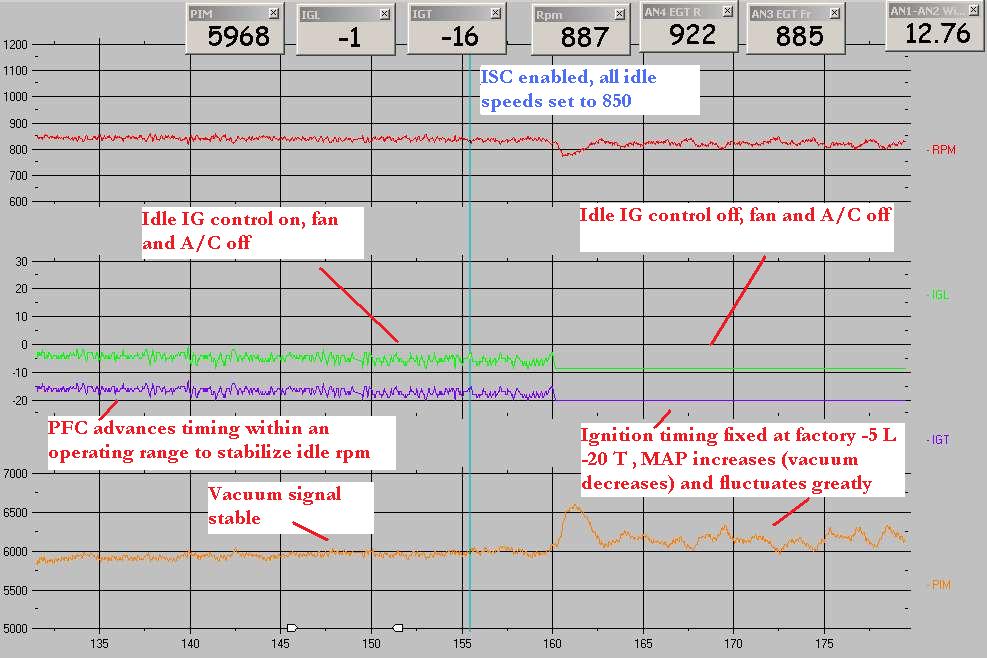

I'm not entirely sure how this precisely applies in your situation. I have done some testing with A/C but not extensive logging. Your vacuum signal is weak even at such high idle speeds. I don't have an HBP car to do any further testing.
One more thing to consider: with the ISC installed, it can sometimes be tricky to get the idle right on deceleration. The ISC virtual-dashpot control logic is a little tough. The most common problem is the idle hanging up a little bit, but again that's on cars with less porting and lower idle speeds. Usually this is corrected by adjustment of the TB screws, by lowering the fuel cut speeds, and sometimes by adjusting the mechanical dashpot on the TB itself.
To me, with a HBP it's a toss up as to whether you want to keep the ISC. If you had no A/C I would definitely tell you to ditch it, but with A/C it's a tough call.
If I run an ISC then the PFC goes through the idle learn process, I set idle speeds for N/L, E/L, and AC. The PFC then controls air, timing, and fuel to maintain idle speeds. And I have no control over idle timing. This is the only way the PFC can work with an ISC. Is that correct?
For each idle speed (N/L, E/L, AC) there are base timing values. For example, under no load the base speed is -5 L, -20 T BTDC, at least when idle speeds are under 1000rpm (not sure about over 1000). These are the same idle timing values that the FSM calls for, and are the same timing values that older 13B's needed to be set to with a timing light. With Idle IG control OFF, the idle timing will remain at this base value. With Idle IG control ON, the PFC will enter a closed loop strategy to adjust the timing based on the target idle speed. If you raise the target idle speed with Idle IG control on, the PFC will advance the timing while retaining a closed loop oscillation.
I'm not entirely sure how this precisely applies in your situation. I have done some testing with A/C but not extensive logging. Your vacuum signal is weak even at such high idle speeds. I don't have an HBP car to do any further testing.
One more thing to consider: with the ISC installed, it can sometimes be tricky to get the idle right on deceleration. The ISC virtual-dashpot control logic is a little tough. The most common problem is the idle hanging up a little bit, but again that's on cars with less porting and lower idle speeds. Usually this is corrected by adjustment of the TB screws, by lowering the fuel cut speeds, and sometimes by adjusting the mechanical dashpot on the TB itself.
To me, with a HBP it's a toss up as to whether you want to keep the ISC. If you had no A/C I would definitely tell you to ditch it, but with A/C it's a tough call.
Hbp's usually need higher idle speeds anyways. I would try it with the isc if the idle speed is important to you, if you have trouble then hook the isc up only for high load and run manual idle control.
Chuck, when you are running the ISC for high load, are you just continuously supplying +12V to the factory ISC valve? I did that one time on a test bench to an ISC valve for a 2nd gen. The coil got pretty hot in a short period of time, but maybe the coil in the FD ISC can take it. And are you switching it off the A/C signal coming out of the PFC? or off the ELD output signal?
The more I think about it, the more I think it would be better just to skip the ISC on a half bridgeport car, and only because the PFC really does not give you much control over ISC behavior. Or at least, I wouldn't go out of my way to acquire an ISC valve in your case. Open the throttle adjust screw and the air adjusting screws so the thing idle at about 1100-1200. Set the fuel cut speeds to 1500 and idle speeds to zero. Start by setting idle timing to at least 20 degrees leading and maybe 2 or 3 split, otherwise experiment with negative split. If you have stalling issues on deceleration, adjust the mechanical dashpot on the throttlebody.
It's a half bridge, you knew you would be sacrificing a low/quiet idle in the first place.
You're probably right. I may not have known what the characteristics of the HBP were but I SHOULD have done more research. Probably still would have ended up with this setup because rebuilding what I already had was the most economical and the easiest to do. Some day I'll probably replace this engine with a mild street port. But for now I'll put up with it and try to make it as drivable as possible.
According to the FSM the ISC is controlled by a 244 hz constant frequency duty cycle. What is that anyway? And where does it come from? I just assumed the power was the B/W which feeds a number of the engine control devices and it was the ECU which turned it on and off.
And how does that relate to the 12v signal you guys have been talking about to control the ISC?
Chuck, when you are running the ISC for high load, are you just continuously supplying +12V to the factory ISC valve? I did that one time on a test bench to an ISC valve for a 2nd gen. The coil got pretty hot in a short period of time, but maybe the coil in the FD ISC can take it. And are you switching it off the A/C signal coming out of the PFC? or off the ELD output signal?
.
.
The way to do it with a stock ISC, is use an inline resistor as large as posible to reduce current flow but still operate properly. Wire it to get the 12V from the wire to the AC clutch and through a HOBBS pressure switch. When boost get over 2 psi, the AC cuts off and the solenoid also turns off.
According to the FSM the ISC is controlled by a 244 hz constant frequency duty cycle. What is that anyway? And where does it come from? I just assumed the power was the B/W which feeds a number of the engine control devices and it was the ECU which turned it on and off.
And how does that relate to the 12v signal you guys have been talking about to control the ISC?
And how does that relate to the 12v signal you guys have been talking about to control the ISC?
The valve is cycled on and off (pulsed ground signal from ECU) a fixed number of times per second, like flicking a light switch rapidly. In this case the valve cycles on and off 244 times a second. What varies is how long the solenoid is on vs how long it is off (pulsewidth). This rapid on/off signal (0 and 1 in a computer) is called a square wave.
On any solenoid valve for this car, the B/W is ignition power controlled by the main relay. The control is done by switching the ground on and off. Duty controlled solenoids cycle rapidly on and off with a frequency for precise control, as I just said. That requires a pulse width modulation driver (PWM) in the ECU. That costs money to manufacture and control, so you can't always duty control everything. Most of the solenoid just turn on and off at specific temperatures, rpms, etc. like the turbo control solenoids.
Thank you for the explanation. If I understand it means the coil (and valve) is turned on and off 244 times a second, which is so short a duration that it essentially remains closed?
Does the ECU, when it thinks more air is required, actually lengthen the time the valve is open by changing (decreasing) the times per second?
So if this solenoid is essentially turned on and off 244 times a second then when you apply the constant 12v to the coil as said in an earlier post maybe that's why it got hot? And if I tried to open it with 12v when say the A/C was turned on perhaps it would get hotter the longer the A/C was on?
I am still thinking about hooking up an ISC. Is there something inherently wrong with a HBP that would make it not work well with the ISC?
Thank you for the explanation. If I understand it means the coil (and valve) is turned on and off 244 times a second, which is so short a duration that it essentially remains closed?
Does the ECU, when it thinks more air is required, actually lengthen the time the valve is open by changing (decreasing) the times per second?
Does the ECU, when it thinks more air is required, actually lengthen the time the valve is open by changing (decreasing) the times per second?
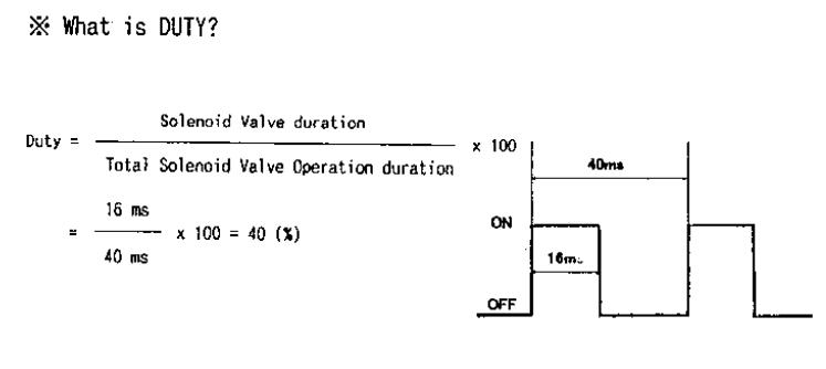
Total time / time spent ON = Duty %
The 16ms is the pulsewidth. The 40ms is the total time interval with which we are measuring. Longer pulsewidths (measured in milliseconds) correspond to higher duty rates. It is the exact same princple as fuel injector pulsewidth and duty cycle. On an ISC valve we are pulling open a spring loaded plunger valve to supply air instead of a needle valve for fuel. They all work the same really.


that's second gen stuff, it's the same basic thing
So if this solenoid is essentially turned on and off 244 times a second then when you apply the constant 12v to the coil as said in an earlier post maybe that's why it got hot? And if I tried to open it with 12v when say the A/C was turned on perhaps it would get hotter the longer the A/C was on?
I am still thinking about hooking up an ISC. Is there something inherently wrong with a HBP that would make it not work well with the ISC?
If you want to keep the ISC valve you are just going to have to keep fiddling with the TB adjustments and the PFC until you get it right. It's a pain in the *** but it usually can be done. You have to balance out the air adjustment screw, the idle speed and fuel cut settings, and the mechanical dashpot on the TB.

Thread
Thread Starter
Forum
Replies
Last Post
Skeese
Adaptronic Engine Mgmt - AUS
65
Mar 28, 2017 03:30 PM