
Cluster issues? My solution...Speedhut gauges retro fit.


Joined: Aug 2004
Posts: 4,786
Likes: 146
From: Colorado Springs, CO
Well, no luck. Actually it's worse with them grounded, because not only does it not work, there is a super annoying infinite beep lol.
This is what I came up with today to ground the board...
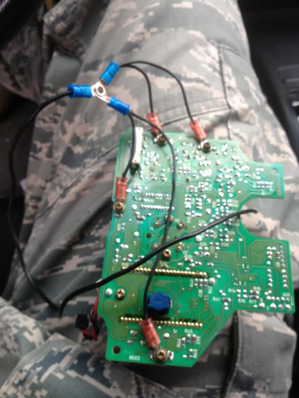
I also grounded one of the spots where there was no screw going into the board, but it said it was a ground, so I figured I wouldn't chance it. Too bad it still didn't work.
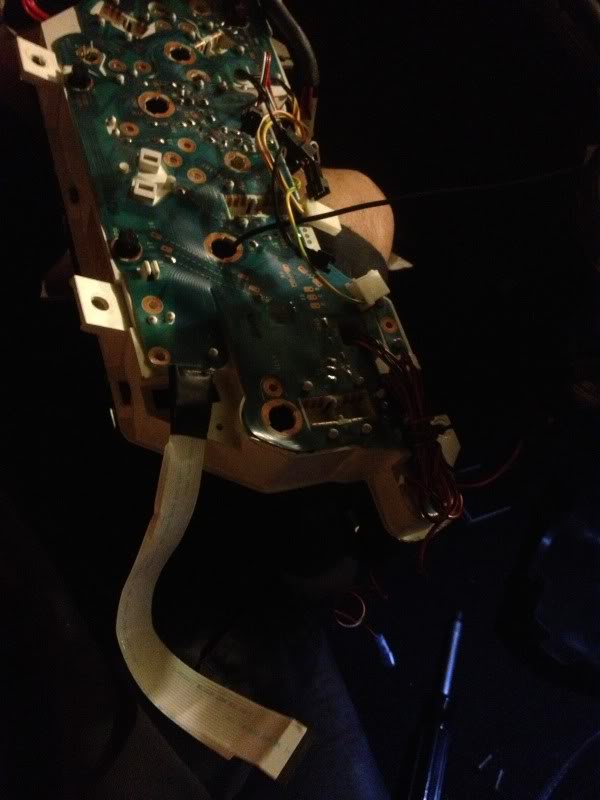
And here is the back of the board, with the extra ribbon soldered on, but I already used liquid tape and electrical tape on the joint so it would be protected. I didn't realize until now how shitty and dark this pic is lol.
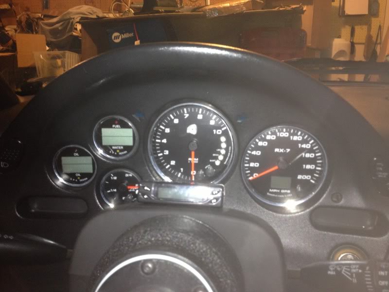
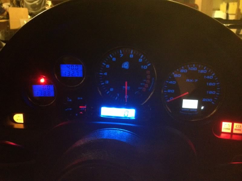
And this is how the gauges came out. I wish they were a little brighter, but oh well. I still love them.
This is what I came up with today to ground the board...

I also grounded one of the spots where there was no screw going into the board, but it said it was a ground, so I figured I wouldn't chance it. Too bad it still didn't work.
And here is the back of the board, with the extra ribbon soldered on, but I already used liquid tape and electrical tape on the joint so it would be protected. I didn't realize until now how shitty and dark this pic is lol.

And this is how the gauges came out. I wish they were a little brighter, but oh well. I still love them.


Joined: Aug 2004
Posts: 4,786
Likes: 146
From: Colorado Springs, CO
That would be great, thanks! My buddy that soldered the board said he'd look through schematics too but he's pretty busy these days. I'm wondering if it needs to be grounded to the circuit board somehow.
Joined: Aug 2004
Posts: 4,786
Likes: 146
From: Colorado Springs, CO
Yeah it worked before the cluster swap, but I also pulled my passenger side airbag at the same time and unplugged the airbag ECU. I also pulled the dash and rebuilt the HVAC boxes but I don't think that would have caused any problems, and I also pulled the old Viper alarm out of the car and respliced wires, which I think probably caused my stock alarm to start working again.
Is the reason for modifying the stock cluster and mounting the gauges that way for aesthetics only? To have all of the gauges flush behind the OEM glass, instead of just say simply placing the new gauges in the holes in the cluster surround?
Joined: Aug 2004
Posts: 4,786
Likes: 146
From: Colorado Springs, CO
I'm also having trouble setting the fuel level on the gauge. First I tried one of their ohm settings but they were close enough. I drained the tank and added a few gallons back in and set it to empty. Then I drove to the gas station and filled it up and set that to full. But now the level isn't dropping and I've been driving the car all weekend. I'm getting really frustrated with this thing.


Joined: Aug 2004
Posts: 4,786
Likes: 146
From: Colorado Springs, CO
Disregard, for some reason I was thinking the stock cluster schematics. Speedhut might help you out but I'm sure it would void your warranty. They're usually pretty good about taking stuff back and fixing it.
Joined: Aug 2004
Posts: 4,786
Likes: 146
From: Colorado Springs, CO
Good news, guys! Another friend and FD owner on this forum (I don't remember his screenname right now) drew up a schematic for a circuit board that should work to get cruise control back, and another friend and FC owner (I'm not sure if he's on this forum but I think so) is finishing up electrical engineering and he's going to make the board and I'm going to try it out. It'll still be a few months because he needs to graduate first and I need to get back to the US haha, but I'll let you guys know how it goes. And I'll talk to them and see if they want to make a few more of these boards for people that want them. I'm not sure what they'll charge for it, that's up to them. FINGERS CROSSED!

Has anyone tried the Dakota Digital converter for conditioning the speed sensor output to the cruise module input?
From my reading it appears that the sgi-5 will downconvert by half an input signal and convert sine to square:
http://www.dakotadigital.com/pdf/sgi-5c.pdf
That seems like it produce a stable enough signal to the cc module to allow it to control speed? I don't think there would be a need for recalibration of the output, according to some reading I have done the range of the cc module is wide, so as long as the signal is within that range and stable my guess is that it might work...
This is basically the reverse use of the sgi-5 from the ls guys, who use it to double the ac sine from their vss to the Mazda speedo and recalibrate.
Lane
Hi Lane, thanks for chiming in! I have read a bit of your postings and about some of your experiences too, glad to see you here....
I started a thread in the 3rd gen section, and did a bit of reading over the weekend and collected some relevant data:
https://www.rx7club.com/3rd-generati...ignal-1076007/
I haven't seen where anyone has measured the output of either the factory or the Dakota box. Based on piecing together the stories from the wiring diagram(voltages) and the service highlights(showing pulsed 1/2 output to ecu/cc), it would appear that the factory unit halves the ppm signal into a 2-2.5v sq pulse, so 8200ppm to 4100ppm.
I actually found a very good description of the internal circuit process somewhere, I will see if I can dig that back up tomorrow. Most of this is above my head electronically, but I'd love to see your arduino solution working. That could be great for all of these use cases.
I'm willing to guinea pig the Dakota on my car when it's back running in a couple of weeks to see if it works. I have a new cluster coming in 5 weeks or so and don't want to lose my cruise.

Hey, guy just brought the speedhut gauges and im just wondering which wire on the ignition module i need tot splice in order to make the Tach working properly? Search and cant seem to find the answer. I look at the wiring diagram and i think it Light Green wire. Please correct me if im wrong. Want to make sure before i start cutting into wire and splicing them.
Thanks
Thanks
Hey guys due to some bad wiring i had to remove my factory harness. which is okay because im full stand alone.
I need to find a good wiring diagram to figure out which wires do what off the back of the factory gauges. I would love to swap them but next year. if anyone has anything that would be awesome thanks!
I need to find a good wiring diagram to figure out which wires do what off the back of the factory gauges. I would love to swap them but next year. if anyone has anything that would be awesome thanks!

It sucks that the picture links throughout this thread are broken. I know Half-Spec did a pretty in depth write up on his setup, but it involved quite a bit more than the average gauge install would be.