
Factory speedometer ECU/Cruise signal


Hi, I am converting my gauges, and want to keep my cruise control.
I've done quite a bit of reading and understand the factory speedo unit takes the speed sensor signal and converts it to another form to send on the the ecu/cc module.
I know others are working on various solutions to this question in cruise equipped cars with gauge swaps as well. It seems that converting the signal using a standard converter(Dakota, etc...) might be possible if we know what both sides are?
Here is some good reading about the issues and potential solutions:
Dale Clark's cc primer:
https://www.rx7club.com/3rd-generati...ntrol-1031871/
Thread with a bit of discussion around the issue and potential solutions starting on p4(Mr Rick):
http://www.rx7club.com/interior-exte...-959423/page4/
Fsm wiring diagram showing speed sensor input/output(Mr Rick):
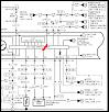
Diagram of conversion, from page 333 of the 93 service highlights(thanks mrgne):
Input PPM signal of stock speed sensor(jimlab):
https://www.rx7club.com/3rd-generati...62/#post613540
In Mr Rick's Speedhut conversion(very nice btw) thread, Speedjunkie discusses someone having evaluated the circuit and possibly building a converter in the near future, which is a great but custom solution.
I do not want to wire up the factory cluster and hide it behind my new cluster, which is a potential solution discussed here and in the ls forums, just one I'd like to avoid if possible here.
My engine and cluster are out, so I cannot check the output on the G/R wire running to the ECU/CC in the diagram above, or the speed sensor output. Know what these signals are seems like a good place to start if anyone has measured them, please let us know.
Thoughts?
Thanks,
Will
94 Wiring Diagram Cruise Section
Pages 111-114 cover the cruise, and indicate the voltage of the input from the speedo(E) alternates 2V and 3V:
https://www.dropbox.com/s/lks0n9f9i9...tages.pdf?dl=0
http://wright-here.net/files/manuals...%20diagram.pdf
https://www.dropbox.com/s/lks0n9f9i9...tages.pdf?dl=0
http://wright-here.net/files/manuals...%20diagram.pdf
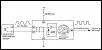
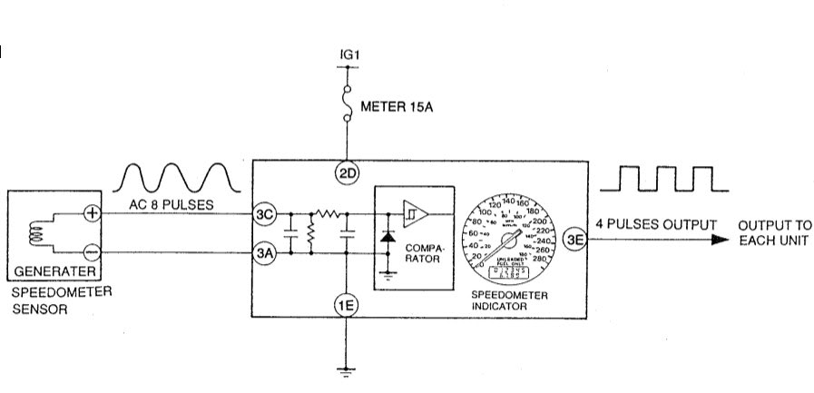
93 Service Highlights for Speedo/Cruise
Info from speedo and cruise sections from 93 service highlights manual. This manual specifies AC-AC conversion in speedo unit:
https://www.dropbox.com/s/s75mtnx94a...ights.pdf?dl=0
http://wright-here.net/files/manuals...highlights.pdf
https://www.dropbox.com/s/s75mtnx94a...ights.pdf?dl=0
http://wright-here.net/files/manuals...highlights.pdf
ECU voltage of speed sensor output
Pages 37-39 of 94 wiring diagram. Shows G/R from speedo(1M) at 2-2.5V while driving. Interesting that doesn't match the alternating 2-3 from the cruise diagram, it's the same wire.
https://www.dropbox.com/s/tfnmg4sklo...tages.pdf?dl=0
http://wright-here.net/files/manuals...%20diagram.pdf
https://www.dropbox.com/s/tfnmg4sklo...tages.pdf?dl=0
http://wright-here.net/files/manuals...%20diagram.pdf
Will
First off Bravo on your research. I've skimmed over this data in the past but pulling it all together is work that should definitely be commended.
After reading over the data again the converted pulse train is less of a mystery to me than the raw speed signal. Like you mentioned the pulse train amplitude changes around a little bit, but knowing automotive electrical signals this isn't uncommon. What's important to note is the limits of the signal. Keeping the amplitude between 2-5v is what's important.
I'd say you've provided definitive proof that the signal is indeed halved from the raw signal to the recompiled pulse train. At least I'm convinced. Good job.
The raw speedo signal is what's puzzling me. I'm just curious if it's a 'real' sine wave. Real as in producing positive and negative voltage swings. Also, I'm curious what its amplitude would be. I'm not really concerned; just curious. The circuit I'm designing should be able to read the frequency of any waveform with amplitudes of up to 35V. Still, it would be fun to scope the raw output from the speed sensor to see exactly how it behaves. I might just have to buy a speedo sensor second hand and hook it up to my scope to see what's what
Keep in touch. If our timelines workout and you're willing to do some testing I may hook you up with some prototypes.
Lane
Thanks Lane!
The answers for us are somewhere in that data, getting it together was a good start
I will keep in touch, and should have my new cluster in 5-6 weeks. I'm going to use my factory panel in the meantime, but may try wiring in the SGI-5 instead of my speedo during the run-in drive around time(when I'm together in a couple of weeks) to see if it actually works. If for no other reason than anecdotal data and knowledge....
Your approach should resolve this and the other handful of issues for both the rotary and piston communities, which is awesome! I had asked a couple of folks if they had scoped the up/down signals, and I think you may be the first if you did it...
Seems kinda silly to me for mazda to have converted the signal midstream to start with, but having a versatile box with dynamic range to accept whatever is thrown at it and output something useful is the solution for sure to bypassing the factory circuit in any direction. I'm happy to help however I can support your effort - I'll watch for a used manual speed sensor too and lend my setup for testing whenever.
Will


Joined: May 2005
Posts: 3,243
Likes: 42
From: Kennewick, Washington
If I had a way to bench test, I would totally scope it out for you. But mine is torn to pieces amd I am in yhe same boat as you. Want to retain cruise without having to Mickey Mouse the old speedo into a custom dash.
Trending Topics
If anyone wants to send me a cluster I'd be happy to scope the input and output. I already have a harness built to power a fd cluster out of the car as well as a stock speed sensor headed my way. All I have to do is rig up a way to turn the speed sensor (electric drill if nothing else).
Pm me in anyone is interested. It'll only take a few days and I'll handle shipping.
Lane
Pm me in anyone is interested. It'll only take a few days and I'll handle shipping.
Lane
Will be great to actually see it scoped out!

Thread
Thread Starter
Forum
Replies
Last Post
Farkel
3rd Generation Specific (1993-2002)
4
Sep 16, 2015 06:16 PM
windom
Adaptronic Engine Mgmt - AUS
4
Sep 11, 2015 04:48 AM