
Cluster issues? My solution...Speedhut gauges retro fit.


Joined: Aug 2004
Posts: 4,786
Likes: 146
From: Colorado Springs, CO
Cruise Control update
So as it turns out the little circuit board my buddy made does work, I just didn't have one of the wires spliced into the stock wire well enough, it wasn't even making contact. There is still an issue but I think it can be fixed. It won't hold speed above 50mph, but I tried everything between 10mph and 50mph and they all worked, and all the stock buttons worked.
SO CLOSE!
SO CLOSE!


Joined: May 2005
Posts: 3,243
Likes: 42
From: Kennewick, Washington
So as it turns out the little circuit board my buddy made does work, I just didn't have one of the wires spliced into the stock wire well enough, it wasn't even making contact. There is still an issue but I think it can be fixed. It won't hold speed above 50mph, but I tried everything between 10mph and 50mph and they all worked, and all the stock buttons worked.
SO CLOSE!
SO CLOSE!
I believe it is supposed to function from approximately 20-100mph. This means your pulse count/time is currently about double what the cruise computer is expecting to see at a given speed.
At least, that is my ever-so-slightly educated guess on this topic.
Last edited by Monkman33; Sep 17, 2016 at 01:09 AM.
Joined: Aug 2004
Posts: 4,786
Likes: 146
From: Colorado Springs, CO
Well your ever-so-slightly educated guess HAS to be more accurate than my not-even-close-to-an-educated-guess lol.
I'll run that by the two mad scientists and see what they think about how to remedy it. I'm very excited about having/getting cruise control again, although I hardly ever have a reason to use it lol.
I'll run that by the two mad scientists and see what they think about how to remedy it. I'm very excited about having/getting cruise control again, although I hardly ever have a reason to use it lol.
Joined: May 2005
Posts: 3,243
Likes: 42
From: Kennewick, Washington
Well your ever-so-slightly educated guess HAS to be more accurate than my not-even-close-to-an-educated-guess lol.
I'll run that by the two mad scientists and see what they think about how to remedy it. I'm very excited about having/getting cruise control again, although I hardly ever have a reason to use it lol.
I'll run that by the two mad scientists and see what they think about how to remedy it. I'm very excited about having/getting cruise control again, although I hardly ever have a reason to use it lol.
Last edited by Monkman33; Sep 17, 2016 at 12:19 PM.
Joined: May 2005
Posts: 3,243
Likes: 42
From: Kennewick, Washington
Here is a conversation that HalfSpec and I had on this topic, posted with permission, and some personal chat has been removed to keep the post on topic:
HalfSpec/Lane has been beyond helpful even though he is busy with other things, so a big thank you for his input is merited.
Originally Posted by Monkman33
Lane,
If you decide to ever make anything electronic, I'm having a heck of a time trying to figure out how to keep cruise while going to speedhut gauges. I am currently looking at the electronic speedos they offer (non gps) since they have a cruise output. Just not sure if the cruise output will be the right pulse count for the FD cruise.
Nathan
Originally Posted by HalfSpec
Nathan
The cruise control wants a pulse count that's half of the speedo's pulse count. I.E., if you're getting a pulse count out of the speedo's sender unit of 8,200 ppm @ 60 mph (this is actually what it puts out), the cruise control would want 4,100 ppm @ 60 mph.
The only tricky part is that the FD's speed sensor outputs a true sine wave. 0Hz for 0MPH, 137Hz for 60MPH, and 410Hz for 180MPH. That's a true sine wave which oscillates between a positive and negative voltage. This goes straight to the Speedo and it moves the speedo's needle:
http://vid917.photobucket.com/albums...psqlimrbmq.mp4
The speedo then 1/2s this frequency and sends it to the CC as a open collector signal. The CC unit expects an input that provides a GROUND at the half the frequency of the speedo. This may sound strange if you aren't familiar with open collector + pullup resistor waveforms, but the end result is that a pulse train waveform is created from this grounding pattern which is input into the CC unit at half the frequency of the speedo's sender output. This is the best diagram I have that explains the process:
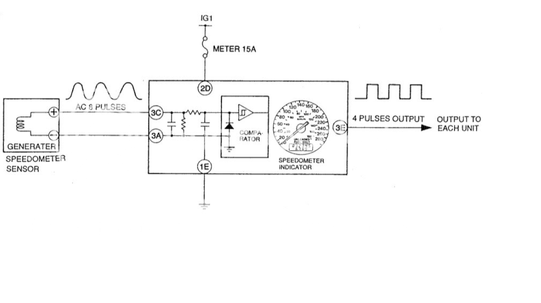
I say all that to say, the Dakota SGI-5E technically has the hardware to do the job:
Universal Speedometer Signal Interface
I wrote the above description so you can get an idea of what needs to be done so you can have a conversation with Dakota or Speedhut if you wish. I certainly can't spare the time to work through or debug an installation with the SGI-5E, but if Dakota will take the time to walk you through the process, maybe it will be a viable solution. Same goes with Speedhut. If they can confirm their speedo can accept a sinewave input and output an open collector signal at half the frequency of the input signal you should be in business, but your on your own with either option.
Looking at the SGI-5E manual I'd say you'd want to use the Signal In to accept the FD speedo sender's sinewave output and use the calibrated 'oc' output signal (Out 2) to send the open collector signal to the CC at half the frequency of the input signal.
Hope that helps
Lane
The cruise control wants a pulse count that's half of the speedo's pulse count. I.E., if you're getting a pulse count out of the speedo's sender unit of 8,200 ppm @ 60 mph (this is actually what it puts out), the cruise control would want 4,100 ppm @ 60 mph.
The only tricky part is that the FD's speed sensor outputs a true sine wave. 0Hz for 0MPH, 137Hz for 60MPH, and 410Hz for 180MPH. That's a true sine wave which oscillates between a positive and negative voltage. This goes straight to the Speedo and it moves the speedo's needle:
http://vid917.photobucket.com/albums...psqlimrbmq.mp4
The speedo then 1/2s this frequency and sends it to the CC as a open collector signal. The CC unit expects an input that provides a GROUND at the half the frequency of the speedo. This may sound strange if you aren't familiar with open collector + pullup resistor waveforms, but the end result is that a pulse train waveform is created from this grounding pattern which is input into the CC unit at half the frequency of the speedo's sender output. This is the best diagram I have that explains the process:
I say all that to say, the Dakota SGI-5E technically has the hardware to do the job:
Universal Speedometer Signal Interface
I wrote the above description so you can get an idea of what needs to be done so you can have a conversation with Dakota or Speedhut if you wish. I certainly can't spare the time to work through or debug an installation with the SGI-5E, but if Dakota will take the time to walk you through the process, maybe it will be a viable solution. Same goes with Speedhut. If they can confirm their speedo can accept a sinewave input and output an open collector signal at half the frequency of the input signal you should be in business, but your on your own with either option.
Looking at the SGI-5E manual I'd say you'd want to use the Signal In to accept the FD speedo sender's sinewave output and use the calibrated 'oc' output signal (Out 2) to send the open collector signal to the CC at half the frequency of the input signal.
Hope that helps
Lane
Originally Posted by monkman33
Lane,
You're going to **** a brick. I looked at the different speedos from speedhut. The programmable digital has the output for a cruise control, and get this; its at 4000 ppm, square wave 0-5v. The GPS speedo does not.
However, I called speedhut, and for $20, they can add the cruise output to the GPS speedo.
And for 10$ they can change the backlighting color on the lcd.
My entire problem just simplified into a $20 upgrade.
Thank you for the technical insight that will allow me to move forward with this project.
Nathan Monk
Originally Posted by HalfSpec
0-5V square wave output ≠ open collector output. I seriously doubt this is an insurmountable problem, but the fact of the matter is that the Q-01 pos E input to the CC module already has a built in pullup resistor to 5v, because it's anticipating that it needs to pull up the waveform to 5v when the connection to ground via the open collector transistor in the stock cluster has finished its pulse. Two parallel pullups may produce unexpected results. Honestly I don't know exactly what would happen in this situation. Best case, they work together and you simply pull up the waveform faster on the rising edge. Worst case, the parallel pullup is no longer "weak" and overpowers the OC transistor making it so it can't pull the waveform to ground. Medium case, the 5V reference at the other end of each pullup resistor (CC input and the Speedhut speedo output) are not exactly the same 5V which may result in a less precise square wave on the rising edge.
Most designs I've seen that tackle this job at a universal level usually have a pullup resistor that you can disable if there is already a pullup in the circuit which would cancel out any potential problems. If that's not an option, it's still worth a try at $20, but go into it open eyed.
4000 ppm ≠ 4100 ppm. Again, probably not an issue, but a ~2.5% difference in what the CC is told and what the car is actually doing may perhaps cause a noticeable transition when switching over the CC.
I say all that not to dissuade you but rather pick at the details so if it doesn't work straight off the bat you'll have things you can investigate to iron out any problems that could potentially pop up.
If it does work, please let me know. I still get a good bit of PM/Emails from folks like you asking about my old plans and I'd love to have somewhere I can send them for a real solution
Lane
Originally Posted by Monkman33
Lane,
Very good point on the double pull-up. I will ask the guys at speedhut to compare the circuits for compatibility.
As for the 4100, vs 4000.
Since pulses per mile is a distance not a speed, the only parameters that will be affected will be the speed that the cruise control computer thinks the car is going.
So if the cruise compute only activated between 25mph and 100mph, it will now only work between 26 and 102.5 mph.
All cruise does is modulate throttle to match the 'set' speed of the pulses. So if 60mph is 4100 pulses per mile and minute, it will try to keep receiving 4100 pulses per minute.
So the difference would be it would see 4000, and just try to match 4000 pulses per (approx) minute/mile @ 60mph, while it thinks it's at 59 mph or so. But the job of the cruise computer is just a comparator. Read pulse count rate and attempt to keep it. I bet they use a PID style programming. But I don't know for sure.
I am hoping this all works out well. I definitely need to address the signal conflict possibility though. Would suck to get it all together and not have it work.
Nathan Monk
Originally Posted by HalfSpec
I must admit, I have been stuck on signal matching, vs understanding what the CC is actually doing with the signal. Up to this point, I haven't really considered how the CC is doing what it does, I just knew that giving it what the stock cluster gives it would be the best chance for success. That being said, I expect you're 100% correct in how the CC works. That would definitely be the safest / most foolproof way of doing it. If it works as you described, I would agree; the difference between 4100ppm and 4000ppm wouldn't matter.
Lane
Lane
Originally Posted by Monkman33
Lane,
Considering all of the information and insight you've given me, I am honored I could help at all.
So, I was looking at the instructions on the speedo. The bottom has an interesting "optional" method of wiring. Makes me think there is a better chance of it working straight wired.
Or am I getting something backwards in my wiring logic?

Originally Posted by HalfSpec
Good news, based on that diagram and the fact that they recommend a resistance value range, I'm almost certain that the pullup is something they expect you to add/handle. In that case, just leave it off and the CC input will pull the signal up to it's expected 5v.
Just a note, on that diagram they have you connecting the pullup to 12V, which would make a 12V pulse train, not 5V.
Personally, I'd hook it up first without a pullup and see if it works. If it doesn't work as expected and you're out of options, you could try hooking up the external pullup to 12v as a last resort. I feel like it's a band-aid vs solving the root issue, but I know that some folks have solved automotive OC waveform problems by boosting the amplitude of the waveform. In this case you'd be boosting to a 12V waveform. Like I said, I wouldn't try it first, but worst case, its something you could try before giving up and it shouldn't hurt anything.
Best of luck
Lane
Joined: Aug 2004
Posts: 4,786
Likes: 146
From: Colorado Springs, CO
Thanks for posting that! I sent a link to this thread to my two buddies to see what they say. The guy that made the board is going to make another one a little different and see if it works.
I read the first few posts and skimmed through the link for the Dakota Digital interface. I think I have an idea of what the modified Speedhut speedo and Dakota interface would do. But probably not lol.
I read the first few posts and skimmed through the link for the Dakota Digital interface. I think I have an idea of what the modified Speedhut speedo and Dakota interface would do. But probably not lol.

Joined: Aug 2004
Posts: 4,786
Likes: 146
From: Colorado Springs, CO
I got my speedo back from getting modified to run cruise control. Now I just need to figure out what to hook the new wire to. I'll report back once I finish testing it out.
Joined: Aug 2004
Posts: 4,786
Likes: 146
From: Colorado Springs, CO
Turns out the first time I got the gauges back they weren't right, so I sent them back. I got it in and working and cruise control works. It was well worth the $20.

Edit: I re-read through the thread and see that Speedhut can modify the GPS speedo to include the square wave output at 4000 pulses per mile. I will give them a call tomorrow to get this moving. But, can you tell me what you connected the output to get your CC working? Appreciate the help!
Last edited by Four4; Feb 13, 2019 at 05:07 PM.
I just got an email response from Speedhut. I too have a GPS speedo and they said they would add the analog output for $20 + $12 in return shipping. Ill be shipping mine out soon.
Then it appears we tie this new wire into the G/R wire on the OEM speedo plug. At least that is what I am getting from a few threads.
Then it appears we tie this new wire into the G/R wire on the OEM speedo plug. At least that is what I am getting from a few threads.
Joined: Aug 2004
Posts: 4,786
Likes: 146
From: Colorado Springs, CO
Am I correct in assuming you do not have the GPS speedo? You have the programmable speedo? Or, if you do have the GPS speedo, is that was they were able to modify for the $20?
Edit: I re-read through the thread and see that Speedhut can modify the GPS speedo to include the square wave output at 4000 pulses per mile. I will give them a call tomorrow to get this moving. But, can you tell me what you connected the output to get your CC working? Appreciate the help!
Edit: I re-read through the thread and see that Speedhut can modify the GPS speedo to include the square wave output at 4000 pulses per mile. I will give them a call tomorrow to get this moving. But, can you tell me what you connected the output to get your CC working? Appreciate the help!
EDIT: I couldn't find anything where I'd stated it before on any of the forums, but yeah it looks like it's the G/R wire, 3E.
Last edited by speedjunkie; Feb 15, 2019 at 11:26 AM.
Joined: May 2005
Posts: 3,243
Likes: 42
From: Kennewick, Washington
Found out that Speedhut will not do the analog output on the dual gauge gps speedo. i am a bit sad about that as I had done a bunch of planning around the hopes that I would be able to have that capability. Now I have to figure out a different way to condition the signal from the transmission to the proper type/rate.
Joined: Aug 2004
Posts: 4,786
Likes: 146
From: Colorado Springs, CO
Found out that Speedhut will not do the analog output on the dual gauge gps speedo. i am a bit sad about that as I had done a bunch of planning around the hopes that I would be able to have that capability. Now I have to figure out a different way to condition the signal from the transmission to the proper type/rate.

Latest FD cluster iteration done by Toby @ Broadfield Customs using Speedhut gauges...
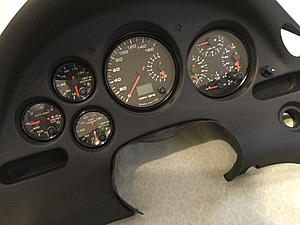
The second IAT gauge is primarily in place to let me know that the pre-turbo WI solenoid is indeed working as anticipated under boost; thermocouple probe located just ahead of intercooler; temps should be relatively cooler when spraying.

The second IAT gauge is primarily in place to let me know that the pre-turbo WI solenoid is indeed working as anticipated under boost; thermocouple probe located just ahead of intercooler; temps should be relatively cooler when spraying.
I figured I'd share my conversion. I decided to use the stock rings that came with the gauges because they're so nice. This required more trimming, but was well worth it. I'm glad a had RHD cluster surround to practice on before I trim up my new cluster surround. Anyways here's the final product on the practice surround.

Junior Member
Joined: Feb 2022
Posts: 17
Likes: 5
From: Spain
Hi all.
First of all, sorry to bring back from history this old topic but I'm trying to read some values with an arduino board and I would need some additional information.
Apparently, the speed sensor sends a sine signal into pin 3C (3A is just Ground reference). But do someone know what is the amplitude of this signal? Is it -5V,+5V or -12V,+12V or something different? I can just take whatever above 2V as "high" to count a cicle, but I would like to know exactly what I will be finding when starting to dig into this.
On the other hand, where the RPMs signal is reaching the dash cluster? From wiring diagram I see three connections to tachometer, ground and two of them coming from chip "CPU & SPEEDOMETER", but no reference to RPMs.
Thank you in advance for your help.
Interestingly, as the speed sensor's output frequency increases, so does its amplitude. I tested this on my scope by wiring the speedo + speed sensor on my bench and manually rotating the FD's speed sensor with a drill while monitoring the raw output. If I recall correctly, it was over 100Vpp before it got to 180MPH. I video'd the experiment and thought I posted it to youtube, but it appears I'm mistaken (as far as youtube goes). I'm sure I've got the vid somewhere. It's not the end of the world for an arduino though. All you'd have to do to clamp the amplitude to say 5v is use a 5v zener diode + resistor, where the resistor is sized to protect the zener:
https://www.electronics-tutorials.ws/diode/diode_7.html
Lane
PS
Oh yeah, I'd probably add a standard diode in series with the resistor to rectify the AC signal so you end up with at the arduino. With the rectified + clamped input circuit your arduino would get a pretty respectable pulse train input.
PPS
Hey! I found the vids and some scope captures. The vids weren't as informative as I remembered, but the captures are. From my a conversations earlier in this thread, this is how the FD's speedo signal relates vehicle speed output frequency:
"0Hz for 0MPH, 137Hz for 60MPH, and 410Hz for 180MPH"
With that in mind, you get amplitude from the scope capture.
Example # 1 =
37.88Hz / 16.6MPH

Amplitude = 16Vpp
Example # 2 =
179.9Hz / 78.98MPH

Amplitude = 46Vpp
I think that's as fast as my drill would go, but you can see the amplitude and frequency are directly related and linear. If I were to get a faster drill and turn the speed sensor faster to get a 410Hz output I would expect a Vpp of ~104Vpp
Hope that helps
Lane
https://www.electronics-tutorials.ws/diode/diode_7.html
Lane
PS
Oh yeah, I'd probably add a standard diode in series with the resistor to rectify the AC signal so you end up with at the arduino. With the rectified + clamped input circuit your arduino would get a pretty respectable pulse train input.
PPS
Hey! I found the vids and some scope captures. The vids weren't as informative as I remembered, but the captures are. From my a conversations earlier in this thread, this is how the FD's speedo signal relates vehicle speed output frequency:
"0Hz for 0MPH, 137Hz for 60MPH, and 410Hz for 180MPH"
With that in mind, you get amplitude from the scope capture.
Example # 1 =
37.88Hz / 16.6MPH
Amplitude = 16Vpp
Example # 2 =
179.9Hz / 78.98MPH
Amplitude = 46Vpp
I think that's as fast as my drill would go, but you can see the amplitude and frequency are directly related and linear. If I were to get a faster drill and turn the speed sensor faster to get a 410Hz output I would expect a Vpp of ~104Vpp
Hope that helps
Lane
Last edited by HalfSpec; Jul 19, 2022 at 03:12 PM.
Junior Member
Joined: Feb 2022
Posts: 17
Likes: 5
From: Spain
Interestingly, as the speed sensor's output frequency increases, so does its amplitude. I tested this on my scope by wiring the speedo + speed sensor on my bench and manually rotating the FD's speed sensor with a drill while monitoring the raw output. If I recall correctly, it was over 100Vpp before it got to 180MPH. I video'd the experiment and thought I posted it to youtube, but it appears I'm mistaken (as far as youtube goes). I'm sure I've got the vid somewhere. It's not the end of the world for an arduino though. All you'd have to do to clamp the amplitude to say 5v is use a 5v zener diode + resistor, where the resistor is sized to protect the zener:
https://www.electronics-tutorials.ws/diode/diode_7.html
Lane
PS
Oh yeah, I'd probably add a standard diode in series with the resistor to rectify the AC signal so you end up with at the arduino. With the rectified + clamped input circuit your arduino would get a pretty respectable pulse train input.
PPS
Hey! I found the vids and some scope captures. The vids weren't as informative as I remembered, but the captures are. From my a conversations earlier in this thread, this is how the FD's speedo signal relates vehicle speed output frequency:
"0Hz for 0MPH, 137Hz for 60MPH, and 410Hz for 180MPH"
With that in mind, you get amplitude from the scope capture.
Example # 1 =
37.88Hz / 16.6MPH
Amplitude = 16Vpp
Example # 2 =
179.9Hz / 78.98MPH
Amplitude = 46Vpp
I think that's as fast as my drill would go, but you can see the amplitude and frequency are directly related and linear. If I were to get a faster drill and turn the speed sensor faster to get a 410Hz output I would expect a Vpp of ~104Vpp
Hope that helps
Lane

This is generating this kind of signal (seems to be working in both extremes of frequency and voltage ranges according to your readings).


I also simulated Arduino code with a very simplistic function that counts microsends when V is high (above 3V) and microseconds when voltage is low (below 3V). Adding them, and divifing 1.000.000 with this value, I get frecuency that then can be converted to KMH or MPH with a conversion factor. As soon as I come back home I will start real testing.


By the way, what about RPMS? Where is this signal arriving to cluster? I assume that it should come from ECU, but I'm not able to find it with electrical diagrams.
Best regards.
Looking good.
I don't know if I've mentioned this, but I actually built a circuit / pcb in ~2015 I think that read the raw speedo output and converted it to pulse train at 1/2 the original frequency via an AVR microprocessor. After that, the AVR would drive a mosfet at that modified frequency which did the heavy lifting talking to the downstream cruise control module.
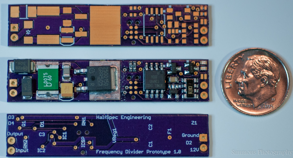
I only mention it because seeing your clamped / rectified signal brought back memories of working on that signal to get sharper transitions from 0 to 5v and back. I.E., the rectified signal still has rounded 0v->5v transitions and rounded 5v->0v transitions because of course, that's what the source / sine wave looks like. If your arduino doesn't mind then its a non-issue. I found that my microprocessor sometimes mis-understood the input and worked much better with a square wave that was really "square." In the end, I utilized an inverter. A fairchild NC7SZ14 to be precise:

The real beauty of the NC7SZ14 is that it has a schmitt trigger input and a very fast acting output. What it effectively does is convert the rounded / rectified AC signal into a sharp square pulsetrain. A side affect is it does invert the signal, but that doesn't bother anything.
Like I said, not required if your arduino is happy.
Two other things I wanted to point out about the circuit before I leave you though. #1 Check out D1 in the circuit above. It's actually an array of schottky diodes that do all the clamping work. Schottkey's are ideal because of their small forward voltage drop. This also helps keep the negative clamp closer to 0v. #2 - I'd recommend bumping your input resistor to 10k vs 1k. While the current moving through the resistor is still within the ratings of a 1/4 watt resistor, your arduino input doesn't need any appreciable amount of current to sense the waveform. 10k will just knock that current down even more. Less current = less heat and less wear and tear on your clamping diodes.
Oh. The tach signal comes out of the B1-01 ECU connector position 2B and comes to the cluster via a Y/L wire on C1-01 position 3F. It's actually a square wave pulse train by default. I don't think it goes above 12v in amplitude. I can't remember its frequency range for 0-9krpm though. If I remember where it might be documented I'll update this post.
Lane
I don't know if I've mentioned this, but I actually built a circuit / pcb in ~2015 I think that read the raw speedo output and converted it to pulse train at 1/2 the original frequency via an AVR microprocessor. After that, the AVR would drive a mosfet at that modified frequency which did the heavy lifting talking to the downstream cruise control module.
I only mention it because seeing your clamped / rectified signal brought back memories of working on that signal to get sharper transitions from 0 to 5v and back. I.E., the rectified signal still has rounded 0v->5v transitions and rounded 5v->0v transitions because of course, that's what the source / sine wave looks like. If your arduino doesn't mind then its a non-issue. I found that my microprocessor sometimes mis-understood the input and worked much better with a square wave that was really "square." In the end, I utilized an inverter. A fairchild NC7SZ14 to be precise:
The real beauty of the NC7SZ14 is that it has a schmitt trigger input and a very fast acting output. What it effectively does is convert the rounded / rectified AC signal into a sharp square pulsetrain. A side affect is it does invert the signal, but that doesn't bother anything.
Like I said, not required if your arduino is happy.
Two other things I wanted to point out about the circuit before I leave you though. #1 Check out D1 in the circuit above. It's actually an array of schottky diodes that do all the clamping work. Schottkey's are ideal because of their small forward voltage drop. This also helps keep the negative clamp closer to 0v. #2 - I'd recommend bumping your input resistor to 10k vs 1k. While the current moving through the resistor is still within the ratings of a 1/4 watt resistor, your arduino input doesn't need any appreciable amount of current to sense the waveform. 10k will just knock that current down even more. Less current = less heat and less wear and tear on your clamping diodes.
Oh. The tach signal comes out of the B1-01 ECU connector position 2B and comes to the cluster via a Y/L wire on C1-01 position 3F. It's actually a square wave pulse train by default. I don't think it goes above 12v in amplitude. I can't remember its frequency range for 0-9krpm though. If I remember where it might be documented I'll update this post.
Lane
Junior Member
Joined: Feb 2022
Posts: 17
Likes: 5
From: Spain
Looking good.
I don't know if I've mentioned this, but I actually built a circuit / pcb in ~2015 I think that read the raw speedo output and converted it to pulse train at 1/2 the original frequency via an AVR microprocessor. After that, the AVR would drive a mosfet at that modified frequency which did the heavy lifting talking to the downstream cruise control module.
I only mention it because seeing your clamped / rectified signal brought back memories of working on that signal to get sharper transitions from 0 to 5v and back. I.E., the rectified signal still has rounded 0v->5v transitions and rounded 5v->0v transitions because of course, that's what the source / sine wave looks like. If your arduino doesn't mind then its a non-issue. I found that my microprocessor sometimes mis-understood the input and worked much better with a square wave that was really "square." In the end, I utilized an inverter. A fairchild NC7SZ14 to be precise:
The real beauty of the NC7SZ14 is that it has a schmitt trigger input and a very fast acting output. What it effectively does is convert the rounded / rectified AC signal into a sharp square pulsetrain. A side affect is it does invert the signal, but that doesn't bother anything.
Like I said, not required if your arduino is happy.
Two other things I wanted to point out about the circuit before I leave you though. #1 Check out D1 in the circuit above. It's actually an array of schottky diodes that do all the clamping work. Schottkey's are ideal because of their small forward voltage drop. This also helps keep the negative clamp closer to 0v. #2 - I'd recommend bumping your input resistor to 10k vs 1k. While the current moving through the resistor is still within the ratings of a 1/4 watt resistor, your arduino input doesn't need any appreciable amount of current to sense the waveform. 10k will just knock that current down even more. Less current = less heat and less wear and tear on your clamping diodes.
Oh. The tach signal comes out of the B1-01 ECU connector position 2B and comes to the cluster via a Y/L wire on C1-01 position 3F. It's actually a square wave pulse train by default. I don't think it goes above 12v in amplitude. I can't remember its frequency range for 0-9krpm though. If I remember where it might be documented I'll update this post.
Lane
Best regards.

Thread
Thread Starter
Forum
Replies
Last Post
Esser
3rd Generation Specific (1993-2002)
193
Aug 16, 2022 07:48 PM
sharingan 19
2nd Generation Specific (1986-1992)
55
Apr 7, 2013 04:55 PM
MR_Rick
Interior / Exterior / Audio
44
Jun 24, 2011 12:34 PM