
Haltech Haltech wiring for E8 to 13b-re

Thread Starter
Rotary Enthusiast


Joined: Aug 2004
Posts: 1,326
Likes: 9
From: Australia - Perth
Haltech wiring for E8 to 13b-re
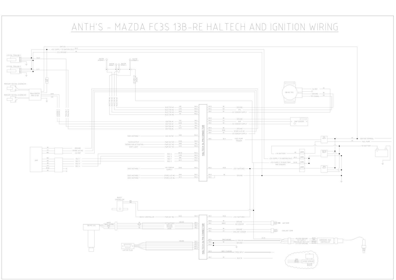
Guys Im going a full new haltech loom and rewing my 13b-re engine.
Ive gone through and fully detailed the entire wiring system for my haltech and ignitions (M&W CDI setup)
Really I just want one for the guys in the know (Claudio RX-7 or BDC ) to have a look and say, yeh that looks all sweet
Any changes are more then welcome, Ive not wired up a engine before.
I also have lots of inputs and outputs Im not using so any advice on those would be good. (see the diagram)
Also hopefully the picture will help others in the future.

Or colour may be easier.

Also where the hell does this speed sensor wire up to ? (I got it with my haltech e8 all second hand) if I cant use it its all good.
Also can someone check my wideband wiring..... I think its all right. but a quick yes or no would help me heaps..
Cheers guys.
-Anth
PS sorry the pic is a bit unclear and simple.. I drew it up in Cad as that's all I know.
I have a PDF copy thats heaps better if anyone would like it.
Ive gone through and fully detailed the entire wiring system for my haltech and ignitions (M&W CDI setup)
Really I just want one for the guys in the know (Claudio RX-7 or BDC
) to have a look and say, yeh that looks all sweet Any changes are more then welcome, Ive not wired up a engine before.
I also have lots of inputs and outputs Im not using so any advice on those would be good. (see the diagram)
Also hopefully the picture will help others in the future.

Or colour may be easier.

Also where the hell does this speed sensor wire up to ? (I got it with my haltech e8 all second hand)
if I cant use it its all good.Also can someone check my wideband wiring..... I think its all right. but a quick yes or no would help me heaps..
Cheers guys.
-Anth
PS sorry the pic is a bit unclear and simple.. I drew it up in Cad as that's all I know.
I have a PDF copy thats heaps better if anyone would like it.
Thread Starter
Rotary Enthusiast
Joined: Aug 2004
Posts: 1,326
Likes: 9
From: Australia - Perth
hmm try this one
Beef, Havnt tested the TPS yet, but onc eI kinda get the ok looks good I will let you know
Also Im assuming thats how you set up the boost controller and just set it to closed loop within Halwin
Also the M&W cdi unit say wire to battery, but since the haltech has a relay and sourse power for it I did it this way... can anyone see any issues ?
Cheers again in advance... Hope this also help others in the future.
(PS if anyone wants the cad file PM me)

By antman01
Last edited by Havoc; Jan 28, 2009 at 07:27 AM. Reason: another question
Trending Topics
Thread Starter
Rotary Enthusiast
Joined: Aug 2004
Posts: 1,326
Likes: 9
From: Australia - Perth
Ideally I would have , but when I bought the E8 the guy was selling it with the Pro12 (So basically cost me nothing and thought I may as well use it.)
So thought Id use it direct fire for my primaries and use some LS1 (or similar ) for the trainings.
C. Ludwig, I know your a bit of a haltech pro, see any issues with my wiring ?
(is there any issues using a common ground with the wideband ?)
Also any sensors you guy recommend that I should use as a input so I can data log better.
(in car gauges I have oil pressure, egt, boost, water temp, fuel pressure)
, but when I bought the E8 the guy was selling it with the Pro12 (So basically cost me nothing and thought I may as well use it.)So thought Id use it direct fire for my primaries and use some LS1 (or similar ) for the trainings.
C. Ludwig, I know your a bit of a haltech pro, see any issues with my wiring ?
(is there any issues using a common ground with the wideband ?)
Also any sensors you guy recommend that I should use as a input so I can data log better.
(in car gauges I have oil pressure, egt, boost, water temp, fuel pressure)
talking head
Joined: Apr 2008
Posts: 2,775
Likes: 15
From: Perth, WA, OZ
arron or JO by chance ?
seems they all come to me , cause at least i know !!!
the four wire jobs have a pin for N/C , ignore it
else once wired up, double check that its not reading 100%
if it is, swap the earth and signal wires !
Ideally I would have , but when I bought the E8 the guy was selling it with the Pro12 (So basically cost me nothing and thought I may as well use it.)
So thought Id use it direct fire for my primaries and use some LS1 (or similar ) for the trainings.
C. Ludwig, I know your a bit of a haltech pro, see any issues with my wiring ?
(is there any issues using a common ground with the wideband ?)
Also any sensors you guy recommend that I should use as a input so I can data log better.
(in car gauges I have oil pressure, egt, boost, water temp, fuel pressure)
, but when I bought the E8 the guy was selling it with the Pro12 (So basically cost me nothing and thought I may as well use it.)So thought Id use it direct fire for my primaries and use some LS1 (or similar ) for the trainings.
C. Ludwig, I know your a bit of a haltech pro, see any issues with my wiring ?
(is there any issues using a common ground with the wideband ?)
Also any sensors you guy recommend that I should use as a input so I can data log better.
(in car gauges I have oil pressure, egt, boost, water temp, fuel pressure)
Makes sense. The price difference between the two is less than $350 is why I asked.
I downloaded your schematic. I'll look at it asap.
talking head
Joined: Apr 2008
Posts: 2,775
Likes: 15
From: Perth, WA, OZ
and the TPS polarity , users note cosmo 13b uses the same 4 wire tps as the 20b , which is a different pin layout to the FD unit
getting it wrong can mean upside down signal, easily checked and corrected
getting it wrong can mean upside down signal, easily checked and corrected
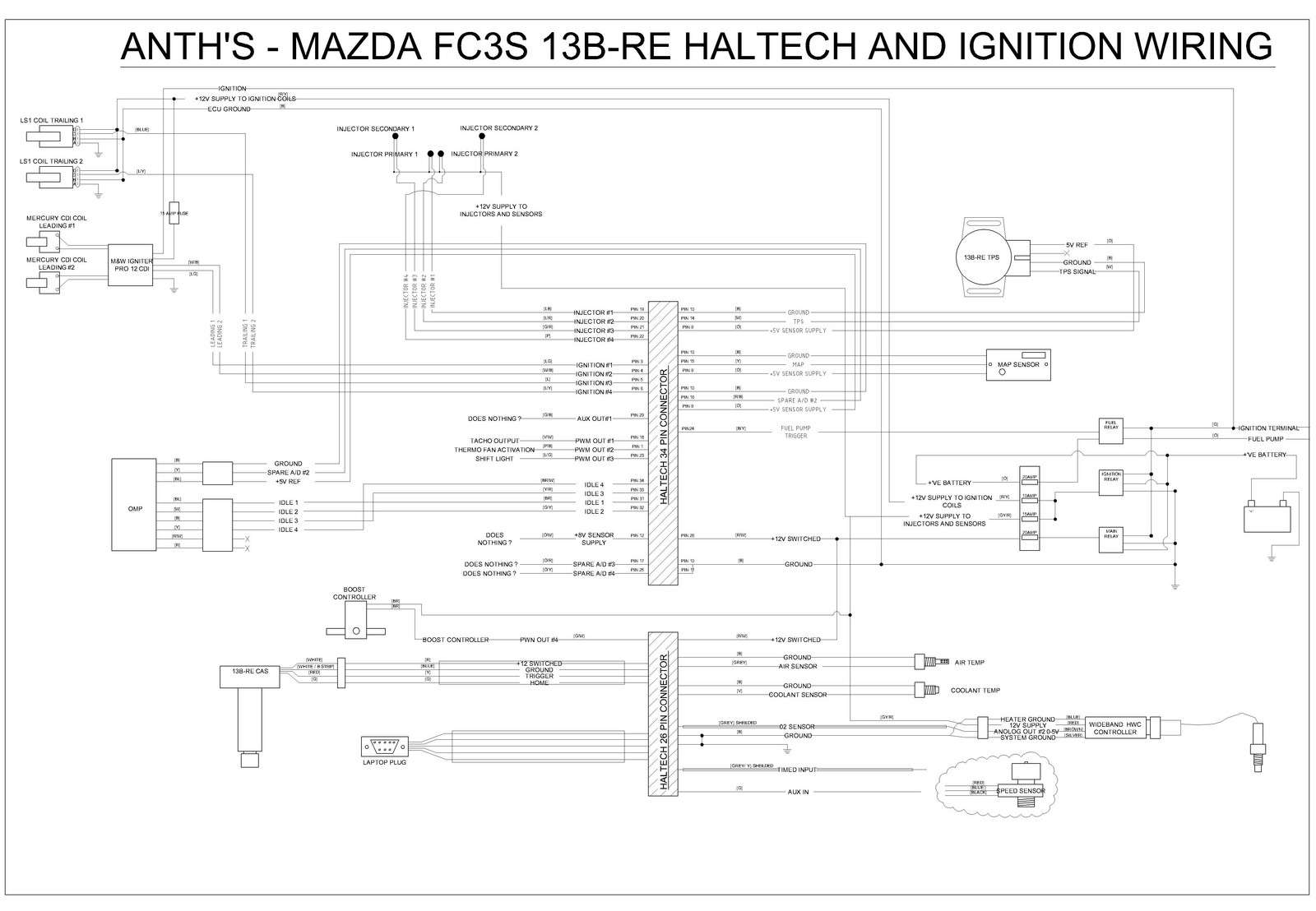
Your CAS wiring is incorrect. The 12V+ is not used. Both of the VE- (white and white/black) go to the Blue wire from the Haltech. The Red wire is not used.
Also, re grounding: IMO all the major electronics should be grounded to a single point on the block (cylinder head of a piston engine). The ignition in particular needs to be grounded at the rotor housings. Using a common ground point for the ECU, wideband, gauges, etc. helps to eliminate ground offsets present when using multiple body ground locations. A heavy ground strap should be run from the battery negative side to the block (head) and then all the important electronics grounded to a single lug on a rotor housing (head).
Also, re grounding: IMO all the major electronics should be grounded to a single point on the block (cylinder head of a piston engine). The ignition in particular needs to be grounded at the rotor housings. Using a common ground point for the ECU, wideband, gauges, etc. helps to eliminate ground offsets present when using multiple body ground locations. A heavy ground strap should be run from the battery negative side to the block (head) and then all the important electronics grounded to a single lug on a rotor housing (head).
Thread Starter
Rotary Enthusiast
Joined: Aug 2004
Posts: 1,326
Likes: 9
From: Australia - Perth
C. Ludwig your a champ thanks for the CAS pickup
As for gounding I'm Im on the same track as you. But will be a issue of doing what I can.
My battery is also mounted in the boot, but nothing more wires cant fix.
Cheers for the help.
I have a updated image that I will post up to help others in the future. (but cant post pics from work.)
Thanks again
thanks for the CAS pickup As for gounding I'm Im on the same track as you. But will be a issue of doing what I can.
My battery is also mounted in the boot, but nothing more wires cant fix.
Cheers for the help.
I have a updated image that I will post up to help others in the future. (but cant post pics from work.)
Thanks again
Re grounding: With the battery relocated the last thing you want to do is simply run a short ground strap from the battery to the body and then rely on the body to carry the load from the engine block. A 2 ga cable is usually sufficient from the battery to the block. This will carry the high current draw of the starter as well as provide for a direct path to the battery for the ignition and other electronics, eliminating ground loops and offsets. Other, less important accessories such as pumps and fans can be grounded to the chassis as necessary. You will need a single strap from the block to the body as well.
Also, thanks for putting that diagram together. It will make things a LOT easier for others to do full installs. If we can get a moderator on this board to do more than chase people off for trying to short change the corporate owner of the board maybe this will get stickied for all to see.
Also, thanks for putting that diagram together. It will make things a LOT easier for others to do full installs. If we can get a moderator on this board to do more than chase people off for trying to short change the corporate owner of the board maybe this will get stickied for all to see.
Also, thanks for putting that diagram together. It will make things a LOT easier for others to do full installs. If we can get a moderator on this board to do more than chase people off for trying to short change the corporate owner of the board maybe this will get stickied for all to see.
Cris, you've got email.

pushing s##t up hill
Joined: Jan 2008
Posts: 1,040
Likes: 0
From: ya mums kitchen
none of them have any input to my car build up, just supply parts , you know who the other person was after the info and i was just trying to help him as we all do, im not even running my cosy manifold until ive ran with the ida setup, its just something that i had to do later on(pinout for cosy tps), and now you guys have sorted that for me
, you know who the other person was after the info and i was just trying to help him as we all do, im not even running my cosy manifold until ive ran with the ida setup, its just something that i had to do later on(pinout for cosy tps), and now you guys have sorted that for me
Thread Starter
Rotary Enthusiast
Joined: Aug 2004
Posts: 1,326
Likes: 9
From: Australia - Perth
Can you send me your diagram to my email? mirkoelek@yahoo.com. I would appreciate this a lot. Did you figure out how to connect speed sensor.

Joined: Feb 2006
Posts: 2,897
Likes: 2
From: Renton/Bellevue/Seattle WA
Does anybody know the answer to this? Can it use the stock knock sensor, or are there any aftermarket sensors it can use?
