
Haltech ECU will not read O2 voltage!


ECU will not read O2 voltage!
Im have a Sprint RE and im having trouble getting the ECU to read whats going on with my AFR's.
I am using a brand new AEM wideband, that puts out the correct voltages at the white wire. I have connected this wire to the Gray/Orange striped wire. (AVI1)
After this, i go into setup, and make sure i have the box checked for o2 wideband, and that the calibration is correct.
when i check the diagnostics page, AVI1 just reads a constant 2.53V at all times. I have no idead what to do now.... someone please help! I have an auto-x on the 22nd and would like to actually drive an event this time..
44 views, no reply?
I cut the wire to the AEM, still reads 2.53 volts.. I have no idea what to do, this harness is basically brand new, and I can chase that wire all the way to the connector, so I have no idea how I could be shorting it out..
Is there any way I could use AVI2 as an input for the o2?!!
I cut the wire to the AEM, still reads 2.53 volts.. I have no idea what to do, this harness is basically brand new, and I can chase that wire all the way to the connector, so I have no idea how I could be shorting it out..
Is there any way I could use AVI2 as an input for the o2?!!
Joined: Sep 2005
Posts: 25,581
Likes: 136
From: Smiths Falls.(near Ottawa!.Mapquest IT!)
I am gonna post this here as I thought it would be good to see some links.
http://forum.aempower.com/forum/inde...c,21559.0.html .The thread has a lot of AEM related product manual instructions.
http://forum.aempower.com/forum/inde...c,21559.0.html .The thread has a lot of AEM related product manual instructions.
If you are absolutely sure that you are getting voltage to the input I would say the next step is to send the unit in to Haltech to check out. I would probably trying applying voltage at the base of the connector first though.
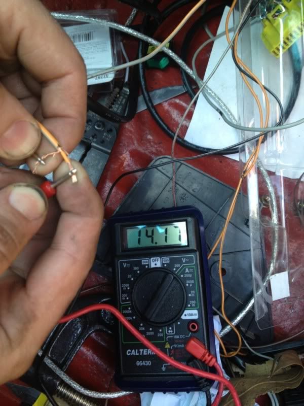
I can disconnect the AEM wire, and avi1 still reads 2.53V on the diagnostics page. The AEM reads fine. I put a multimeter on the white wire and it shows the correct voltage. Also, my fan output wire wasn't working either, so I just used a thermos witch. I don't get it.


The input will float at 2.5v when nothing is connected to it. To test the input to see if it's functioning, you can simply ground the input to see if the voltage falls to 0. If it does, there is nothing wrong with the input.
The next thing you should do is attach a VOM to the output of the wideband itself. See if it is actually outputting a valid signal.
The next thing you should do is attach a VOM to the output of the wideband itself. See if it is actually outputting a valid signal.
Trending Topics
Ludwig, i was hoping you'd drop in  . i have tested the AEM wire. It shows proper voltage. By grounding the O2 wire do you mean just pressing it to a chassis ground? am i splicing it wrong because its shielded?
Also, i noticed in the bundle of AUX rev wires, there is another ground. i do not have this connected. Should I? i dont plan on utilizing the 2 step right now as its not really an issue.
thanks alot!
. i have tested the AEM wire. It shows proper voltage. By grounding the O2 wire do you mean just pressing it to a chassis ground? am i splicing it wrong because its shielded?Also, i noticed in the bundle of AUX rev wires, there is another ground. i do not have this connected. Should I? i dont plan on utilizing the 2 step right now as its not really an issue.
thanks alot!
Are you sure the shielding is not shorting to the actual conductor of the input? There is a gray/orange outer insulation, the shielding braid, and inner orange insulator, and the conductor.
I have the shielding wire pulled completely away from the orange wire underneath. I have it taped off so it can't touch. I'm guessing there has to be a short somewhere under the shielded wire.. Is there any way I can just tap into the wire right after it connects to the ecu?
I'll do that when I get home tonight. Other than this, I believe I've worked out all the bugs. Everything else Haltech wise is working fantastic.
I drove 20 miles to work yesterday, car ran great. My AEM was showing 10:1 in boost (running 8 psi stock turbo) and I have 1600cc's running on 1200cc map. so as soon as I can log AFR I can figure out where I need to pull fuel. I'd like to crank the boost up to around 12psi as well, just hang out like that until I figure out what turbo I wanna go with. Either BNR or Holset.
I drove 20 miles to work yesterday, car ran great. My AEM was showing 10:1 in boost (running 8 psi stock turbo) and I have 1600cc's running on 1200cc map. so as soon as I can log AFR I can figure out where I need to pull fuel. I'd like to crank the boost up to around 12psi as well, just hang out like that until I figure out what turbo I wanna go with. Either BNR or Holset.
Since you have a reading, it means you have continuity somewhere and that means a short with the signal and shield.
The reading shouldn't change from just holding the probes apart and when you touch the two wires.
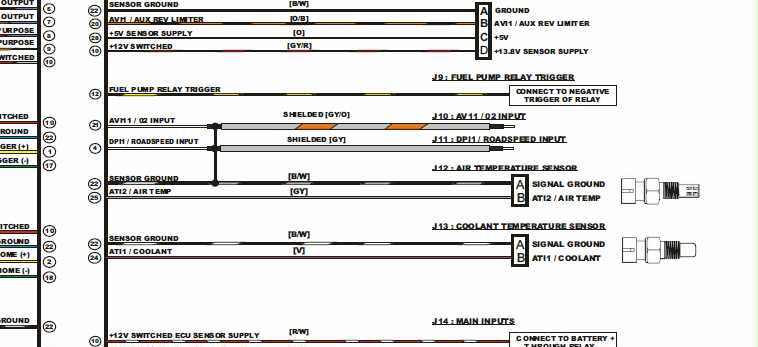
I'd snip that bit off and start over trying to strip the wires. If you haven't damaged the second insulator when stripping (causing the short right right there where you are holding it), you can look at the other end of the harness for a short as well. See the below diagram and how the shielding is grounded to pin 22. As a confirmation, you could check between pin 21 and 22. If you have continuity after you clip off the end of that wire, you have an issue with the harness or the ecu itself.
The reading shouldn't change from just holding the probes apart and when you touch the two wires.
I'd snip that bit off and start over trying to strip the wires. If you haven't damaged the second insulator when stripping (causing the short right right there where you are holding it), you can look at the other end of the harness for a short as well. See the below diagram and how the shielding is grounded to pin 22. As a confirmation, you could check between pin 21 and 22. If you have continuity after you clip off the end of that wire, you have an issue with the harness or the ecu itself.
that wire looks funny to me. should it be an alluminum sheild and an aluminum wire vs copper sheild and copper wire?
maybe your ground is bad?? putting Teflon tape in the air temp sensor will cause resistance in the line.
maybe your ground is bad?? putting Teflon tape in the air temp sensor will cause resistance in the line.
Why would that happen? The ATS has its own ground as shown in the diagram and shouldn't use its "threads" to go to ground.
The wires are copper, and I am not Teflon taping anything. This is starting to annoy me as I have had basically no problems other than this one that seems to not have a solution.
My car runs great, just runs rich in boost. (10:1) I do t want to start taking fuel out until I can log exactly what's going on...
My car runs great, just runs rich in boost. (10:1) I do t want to start taking fuel out until I can log exactly what's going on...
Well, if you don't have a short at the end of the wire, and you still have continuity at pin 21 and 22 with the harness disconnected, then you have a short at the shielding at the other end of the o2 wire (where it leaves the o2 signal wire) and goes to pin22 to find ground.

I guess I'll see if I can take a look at that before work tomorrow. The cool thing about these newer ecu's is that the connector isn't the size of a football and I can remove the entire harness and have it laying on my coffee table in like 5 minutes.