
Haltech E8 and LC-1 into Series 4 FC (Lots-O-Pics)


Thread Starter
Urban Explorer
Joined: May 2009
Posts: 86
Likes: 0
From: dexter mi
E8 and LC-1 into Series 4 FC (Lots-O-Pics)
Starting to install my Haltech E8 into my 87 RX7. I got this E8 way back in 2007 for use on my DSM. Well we all know about those pieces of ****, that car has since been dismanteled, probally sell it for scrap sooner or later.
Anyways, this RX7 came with an E6X on it, and I had the E8 just sitting there begging to be used, so used it shall be. I have photographed all the key compnents.
E8
LS2 coils
Electronic boost controller
innovative wideband
Here is what has been done.
1)A mounting plate was made to hold the E8 verticle, with the connector facing down, hopfully if water finds its way in, it wont puddle up on it and short out all my wires.
2)General routing, its going thru on the passenger side of the firewall, thru the largest hole.
3)A subharness for all the injectors, that way when the engine needs to be removed because I screwed up the calibration the intake manifold dosent have to come off to unplug the injectors and coolant temp sensor.
Here is what has to be done...this list will be alot longer....
1) Figure out which injector wire and ignitor wire on the haltech diagram go to which corresponding mazda part. What I need are those pair of diagrams you get from crutchfield when you get a car stereo.
2)Integrate the wideband into the haltech, I would like to be able to datalog the AFR's, i'm sure the E8 can do this, just gotta figure out how.
3)Electronic cooling fan control. I have wired a flex-a-lite to a 30A relay, the trigger needs to come from the haltech, the old E6X had this working correctly. I think it was a pwm output of some kind.
4)Tach output for an autometer tach. Given how many wires this damn thing has it should be able to spit out a signal for my tach.
5)The E6X has a calibration on it, its one hell of a bitch to start, but it does run, even under WOT. Is it possible to convert the maps on the E6 to the E8 so I can atlest drive the car around and not fry the motor? I believe there is a difference in the resolution, thats essentially why its not a direct cross over. Anyone experienced with these things care to comment?
6) I am sure there are tons of issues that will come up, but off the top of my head this is all I got right now.
Pics thus far...
Coolant temp sensor

Top of motor, can see the various cables coming togeter, one each for primary/sec. injectors and the coolant temp sensor, these will be terminated in a connector for easy servicing. Simply plug it into the haltech harness, and done!
[IMG]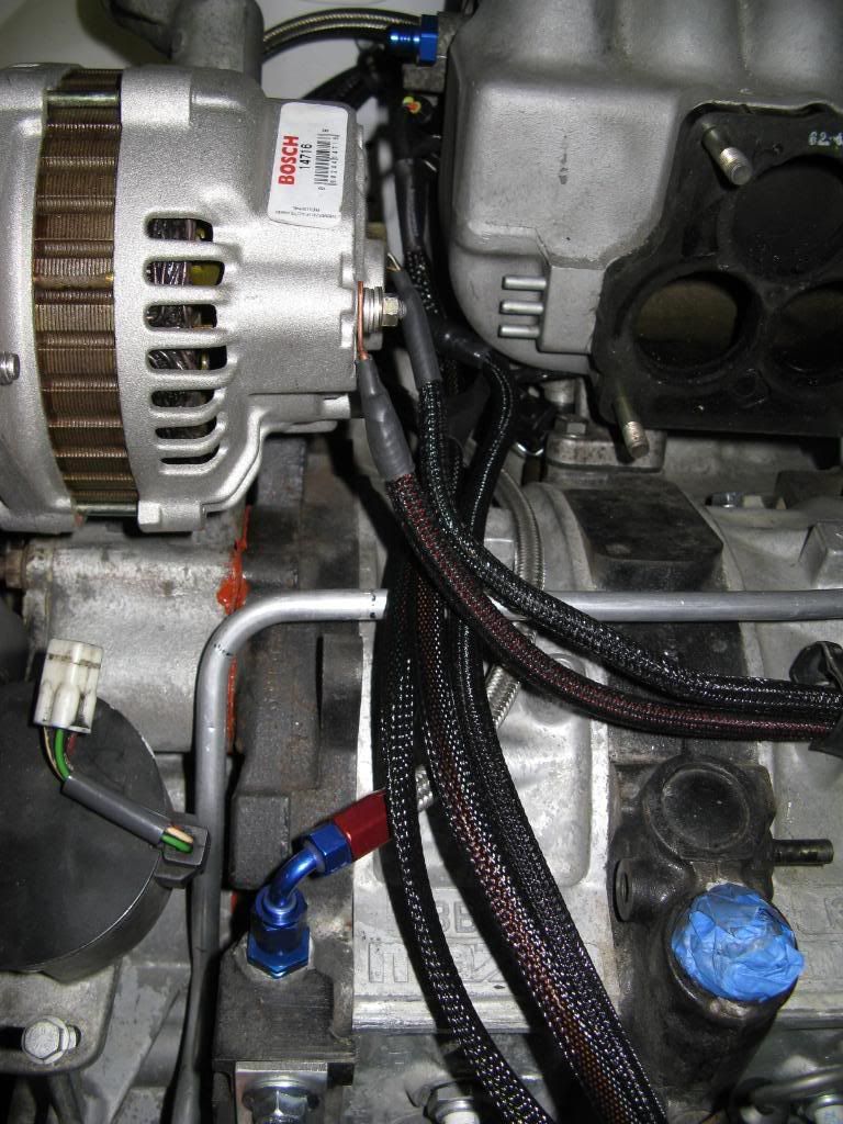 [/IMG]
Injectors
[IMG] [/IMG]
MSD's
[IMG] [/IMG]
DONT EVER BUY LS2 COILS, THE CONNECTOR IS A BITCH TO FIND!! I hear the LS1's take a simple weatherpack 4 pin, but i've never seen them.
[IMG] [/IMG]
I might have to make a cover plate so all the kicking and screaming passengers dont kick the computer.
[IMG] [/IMG]
Wideband...
[IMG] [/IMG]
[IMG] [/IMG]
I hope it all works out.
Cheers and have a good weekend!
Anyways, this RX7 came with an E6X on it, and I had the E8 just sitting there begging to be used, so used it shall be. I have photographed all the key compnents.
E8
LS2 coils
Electronic boost controller
innovative wideband
Here is what has been done.
1)A mounting plate was made to hold the E8 verticle, with the connector facing down, hopfully if water finds its way in, it wont puddle up on it and short out all my wires.
2)General routing, its going thru on the passenger side of the firewall, thru the largest hole.
3)A subharness for all the injectors, that way when the engine needs to be removed because I screwed up the calibration the intake manifold dosent have to come off to unplug the injectors and coolant temp sensor.
Here is what has to be done...this list will be alot longer....
1) Figure out which injector wire and ignitor wire on the haltech diagram go to which corresponding mazda part. What I need are those pair of diagrams you get from crutchfield when you get a car stereo.
2)Integrate the wideband into the haltech, I would like to be able to datalog the AFR's, i'm sure the E8 can do this, just gotta figure out how.
3)Electronic cooling fan control. I have wired a flex-a-lite to a 30A relay, the trigger needs to come from the haltech, the old E6X had this working correctly. I think it was a pwm output of some kind.
4)Tach output for an autometer tach. Given how many wires this damn thing has it should be able to spit out a signal for my tach.
5)The E6X has a calibration on it, its one hell of a bitch to start, but it does run, even under WOT. Is it possible to convert the maps on the E6 to the E8 so I can atlest drive the car around and not fry the motor? I believe there is a difference in the resolution, thats essentially why its not a direct cross over. Anyone experienced with these things care to comment?
6) I am sure there are tons of issues that will come up, but off the top of my head this is all I got right now.
Pics thus far...
Coolant temp sensor
Top of motor, can see the various cables coming togeter, one each for primary/sec. injectors and the coolant temp sensor, these will be terminated in a connector for easy servicing. Simply plug it into the haltech harness, and done!
[IMG]
[/IMG]Injectors
[IMG]
[/IMG]MSD's
[IMG]
[/IMG]DONT EVER BUY LS2 COILS, THE CONNECTOR IS A BITCH TO FIND!! I hear the LS1's take a simple weatherpack 4 pin, but i've never seen them.
[IMG]
[/IMG]I might have to make a cover plate so all the kicking and screaming passengers dont kick the computer.
[IMG]
[/IMG]Wideband...
[IMG]
[/IMG][IMG]
[/IMG]I hope it all works out.
Cheers and have a good weekend!


Good looking work so far. I'll try to lend a little help. The one thing I would caution you to rethink is the routing of the alternator output. It looks like it's going to lay right next to the CAS trigger loom. If that's the case you're asking for trigger issues. Separate the alternator output and the ignition wires for the trigger loom as well as possible. If they must cross each other try to do so at a right angle.
1) The E8 manual outlines which injector connects to which channel of the E8. Easy enough. Same for the coils. Open the manual and scroll all the way to the end and there is a diagram that outlines everything for a 2-rotor. The pinout for the LS2 coils is:
A - Ground
B - Ground
C - Ignition Output From E8
D - 12v Switched From E8
Note that the LS2 coil has a different pinout than the LS1, that catches people out on occasion. I like to ground the coils directly to their corresponding rotor housing.
2) You have the option of using any one a number of different inputs for the wideband. If you aren't going to use a narrow band sensor I like to use the O2 input to leave the other A/D inputs open for other use. Simply connect one of the LC1 output wires to the O2 input. Configure the LC1 output to 0v = 10:1 and 5v = 20:1. This is the default wideband calibration of the Haltech and it's much easier to change the LC1 than it is to get the Haltech to accept a change. Pay attention to the LC1 manual in regard to proper grounding to avoid ground offsets.
3) You can use a PWM output for the fan relay just like you did with the E6X. Pretty much set it up and wire it up just like the E6X. The output will switch to ground to close the relay.
4) Use PWM 1 for the tach. It is the only PWM output that can pull to positive to drive a tach.
5) Unfortunately there isn't a direct import feature for X maps. You can ballpark it though with a spreadsheet and a little time.
Thread Starter
Urban Explorer
Joined: May 2009
Posts: 86
Likes: 0
From: dexter mi
By altornator output you mean the main current line that charges the battery? I'll throw the intake back on and see if there is another way I can route it, possible to put it in some kind of sheething? Is the concern that the altornator output gives some electronic interference, i'l find a new path for it.
cheers
cheers
That's exactly what I was talking about. Guessing you have relocated the battery? The alternator and ignition does give off electrical noise. You wouldn't run that alternator wire right next to a stereo speaker wire right? Same idea.
Thread Starter
Urban Explorer
Joined: May 2009
Posts: 86
Likes: 0
From: dexter mi
I'm on the same page with you now. The way I was going to do it was run the altornator wires down the engine center line, two wires go into the cabin, and the big ones goes to the battery.
I think the subharness is going to have to pass eaither under or over the altornator lines. The CAS lines(not done yet) will be far enough to the drivers side that they will not pass in close proximity to the altornator ****. But the wires for the fuel injectors will, and the coolant temp sensor.
Yes, the battery is under the rear hatch.
I am going to work on the car soon, just gotta eat lunch and do some homework.
The two wires small gauge wires for the voltage regulator on the alternator are not a concern. It's the big one that feeds the battery. When the battery is in the back I'll run that off the driver side of the block to the bottom of the engine and then run it under the car to a grommet in the back where ever I need it. Keep everything separated nicely.
Thread Starter
Urban Explorer
Joined: May 2009
Posts: 86
Likes: 0
From: dexter mi
Continued work on the wiring today.
Made another subharess for the tps/air temp/map sensors. Got the map sensor mounted on the firewall with one bolt, not exactly a top notch job, but it will hold for the duration of the mock up.
Removed the oem connectors on the cas and tps and replaced with some nice weatherpacked units, ones that you can get your hands on if you need them.
[IMG] [/IMG]
[IMG] [/IMG]
My finished sub-harness. TPS/MAP/Air Temp
[IMG] [/IMG]
For the time being I have the subharness attached to the CAS with a p-clamp.
[IMG] [/IMG]
Map sensor on the firewall
[IMG] [/IMG]
Routing of the important cables
[IMG] [/IMG]
Slow and steady progress. Trying to get the calibration off my old E6, I have it on the living room floor attached to my computer, but it needs 12 volts to fire up, guess I will have something to do tomorrow.
cheers
Made another subharess for the tps/air temp/map sensors. Got the map sensor mounted on the firewall with one bolt, not exactly a top notch job, but it will hold for the duration of the mock up.
Removed the oem connectors on the cas and tps and replaced with some nice weatherpacked units, ones that you can get your hands on if you need them.
[IMG]
[/IMG][IMG]
[/IMG]My finished sub-harness. TPS/MAP/Air Temp
[IMG]
[/IMG]For the time being I have the subharness attached to the CAS with a p-clamp.
[IMG]
[/IMG]Map sensor on the firewall
[IMG]
[/IMG]Routing of the important cables
[IMG]
[/IMG]Slow and steady progress. Trying to get the calibration off my old E6, I have it on the living room floor attached to my computer, but it needs 12 volts to fire up, guess I will have something to do tomorrow.
cheers
Trending Topics
Thread Starter
Urban Explorer
Joined: May 2009
Posts: 86
Likes: 0
From: dexter mi
I have the calibration off my E6X now, had to bring a battery charger in the house to power up the ecu.
I am sure some of the settings will need to be changed, as best as I can remember the only things that will be changed are the ign. coils. From Stock to LS2 units.
the only other problem will be getting the CAS installed correctly, i'll have to look at the FSM on that, I thew it in the motor to get the layout right.
Got all the necessary wires bundled together and put in sheething. Routed into the enging bay.
getting closer each day!
pics later tonight or tomorrow.
pics later tonight or tomorrow!!
BDC Motorsports
Joined: Jun 2002
Posts: 3,667
Likes: 6
From: Grand Prairie, TX
BDC Motorsports
Joined: Jun 2002
Posts: 3,667
Likes: 6
From: Grand Prairie, TX
I have the calibration off my E6X now, had to bring a battery charger in the house to power up the ecu.
I am sure some of the settings will need to be changed, as best as I can remember the only things that will be changed are the ign. coils. From Stock to LS2 units.
the only other problem will be getting the CAS installed correctly, i'll have to look at the FSM on that, I thew it in the motor to get the layout right.
Got all the necessary wires bundled together and put in sheething. Routed into the enging bay.
getting closer each day!
pics later tonight or tomorrow.
pics later tonight or tomorrow!!
I am sure some of the settings will need to be changed, as best as I can remember the only things that will be changed are the ign. coils. From Stock to LS2 units.
the only other problem will be getting the CAS installed correctly, i'll have to look at the FSM on that, I thew it in the motor to get the layout right.
Got all the necessary wires bundled together and put in sheething. Routed into the enging bay.
getting closer each day!
pics later tonight or tomorrow.
pics later tonight or tomorrow!!
- Remove the black cap off the CAS.
- Manually crank the engine over to 5*ATDC (yellow mark on the crank pulley lined up with the timing mark on the front cover)
- Align the CAS's gear (on the bottom) with center notch to line up with the marker on the aluminum body
- Properly aligned, the two Home points on the top of the gear will be aligned to about 2:30 and 8:30 o'clock
- With your thumbs holding the gear/shaft in place on the top, insert the CAS. It should sit around 2:30 and 8:30 o'clock orientation.
B
Thread Starter
Urban Explorer
Joined: May 2009
Posts: 86
Likes: 0
From: dexter mi
BDC,
thanks for that. The problem I am having is not installing the CAS so much, its getting the engine at the correct place. My crank pulley is not so new and I cannot tell where the dot is.
Is it just painted on, or is there an indentation? If its punched in the pulley i could blast it and then I would know for sure. Probally the best thing to do would be get a clean pulley, maby one that matchs my altornator pulley.
Havent got a lot of work done since the weekend. Basically gather together the essential wires for the engine and got them in sheething, since then been playing around with how to route the main harness.
[IMG] [/IMG]
[IMG] [/IMG]
[IMG]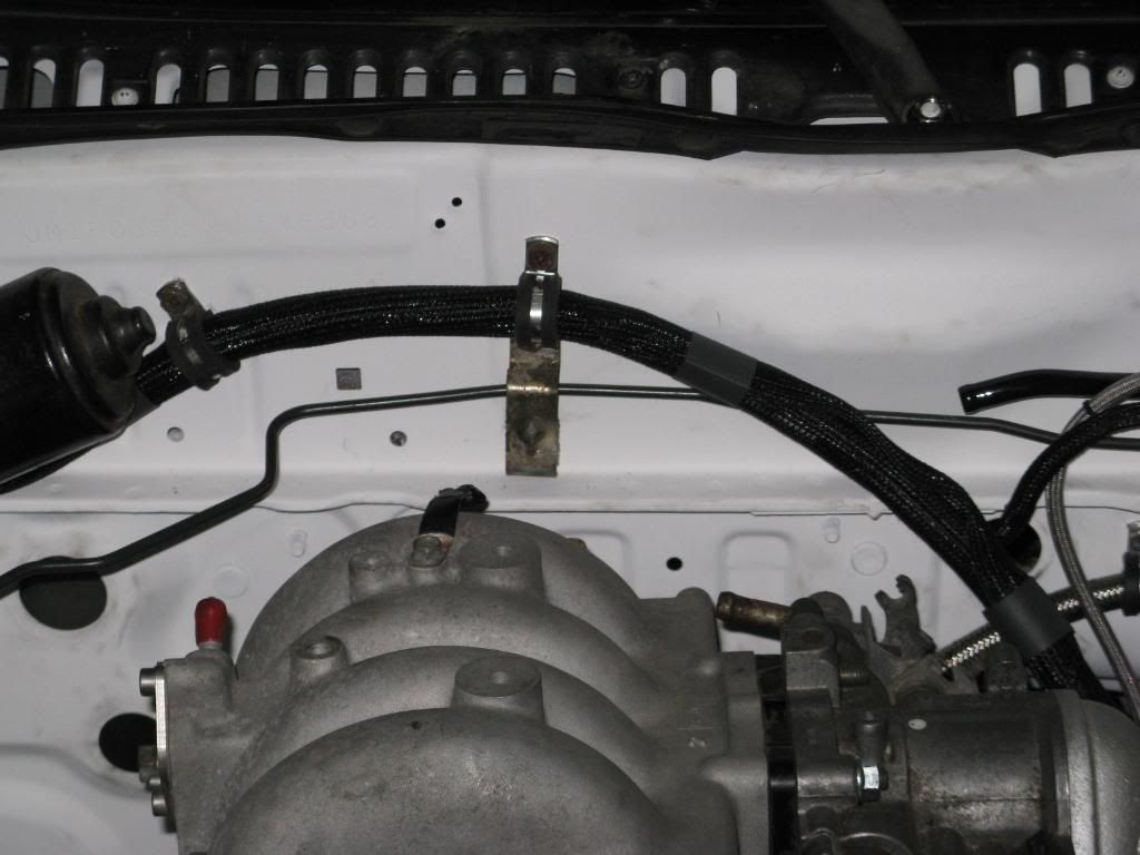 [/IMG]
[IMG] [/IMG]
Got my calibration off my old E6X, made a mess in the house....
[IMG] [/IMG]
what you guys think so far?
cheers
thanks for that. The problem I am having is not installing the CAS so much, its getting the engine at the correct place. My crank pulley is not so new and I cannot tell where the dot is.
Is it just painted on, or is there an indentation? If its punched in the pulley i could blast it and then I would know for sure. Probally the best thing to do would be get a clean pulley, maby one that matchs my altornator pulley.
Havent got a lot of work done since the weekend. Basically gather together the essential wires for the engine and got them in sheething, since then been playing around with how to route the main harness.
[IMG]
[/IMG][IMG]
[/IMG][IMG]
[/IMG][IMG]
[/IMG]Got my calibration off my old E6X, made a mess in the house....
[IMG]
[/IMG]what you guys think so far?
cheers

http://cgi.ebay.com/ebaymotors/LS2-C...Q5fAccessories
Yep that took me about 15seconds to find. D581 are the ls2 coils and the D585 are the yukon/escalade coils that the lsx guys are getting 15hp out of with just new coils.
I use to run 4 D585. Now i run 2 D585 trailing and 2 8247 MSD coils leading. The MSD 8247's use the same ls2 pigtale
Thread Starter
Urban Explorer
Joined: May 2009
Posts: 86
Likes: 0
From: dexter mi
wiring the boost control solenoid now.
one wire comes from a haltech pwm output, the other says 12volts switch (no polarity) does this mean it can go to a hot 12 volts or to ground? does it matter?
cheers
one wire comes from a haltech pwm output, the other says 12volts switch (no polarity) does this mean it can go to a hot 12 volts or to ground? does it matter?
cheers
Either wire on the boost solenoid can go to ground or positive. The ECU supplies a switched ground via the PWM output so the other side of the solenoid needs to go to switch 12v+.

Thread Starter
Urban Explorer
Joined: May 2009
Posts: 86
Likes: 0
From: dexter mi
beefhole,
I got the sheeting from terminal supply company in troy michigan. They have a nice website, check it out.
But it looks as if buyheatshrink.com has a better selection, probably better prices also. You can get different colors too!!
anyone got any ideas about converting the E6 code to E8???
cheers
I got the sheeting from terminal supply company in troy michigan. They have a nice website, check it out.
But it looks as if buyheatshrink.com has a better selection, probably better prices also. You can get different colors too!!
anyone got any ideas about converting the E6 code to E8???
cheers
Thread Starter
Urban Explorer
Joined: May 2009
Posts: 86
Likes: 0
From: dexter mi
About time for an update...
Have been keeping busy with all sorts of time consuming stuff.
I moutned the boost controller on the right strut tower, using two exhisting M6 threaded holes.
[IMG] [/IMG]
I would like to get some proper spaces, but for now these nuts will have to do.
[IMG] [/IMG]
Went from this...
[IMG][/IMG]
To this...all in one day!
[IMG] [/IMG]
Really need to find metripack 150 series 30 pin connector, someday this will have to be done over, it looks as bad as a rats nest!
I hope I did not make a mistake.
I spent alot of time today looking around rx7 club for the necessary info on hooking up the oem mazda sensors to the E8.
I did power up the E8 and went to the engine data page, with my map sensor hooked up it read about -50kPa, and I think tps was around 30. I wiggled the throttle shaft and it appears to work. I stuck an air gun on the nipple of the MAP sensor and got it up too about +3kPa. Given the amount of air i was putting into it it seems to have the correct variation, just not the correct values. I was under the assumption that the map reads gauge pressure, so it should have been zero and probally around 100kPa with the air gun in it. (its a small air gun)
I turned the engine over by hand and got no life out of the CAS. This little guy has me worried. Air temp isint hooked up so it was an open circuit, it was at its max value as expected.
I read on here eariler that the 12V+ isint used on the trigger input for a FC S4 CAS. Can someone confirm this?
Also the white and white/black go to the blue ground on the haltech,(insde the 4core grey).
Slowly getting issues sorted out...
thanks for any help in advance.
Have been keeping busy with all sorts of time consuming stuff.
I moutned the boost controller on the right strut tower, using two exhisting M6 threaded holes.
[IMG]
[/IMG]I would like to get some proper spaces, but for now these nuts will have to do.
[IMG]
[/IMG]Went from this...
[IMG]
[/IMG]To this...all in one day!
[IMG]
[/IMG]Really need to find metripack 150 series 30 pin connector, someday this will have to be done over, it looks as bad as a rats nest!
I hope I did not make a mistake.
I spent alot of time today looking around rx7 club for the necessary info on hooking up the oem mazda sensors to the E8.
I did power up the E8 and went to the engine data page, with my map sensor hooked up it read about -50kPa, and I think tps was around 30. I wiggled the throttle shaft and it appears to work. I stuck an air gun on the nipple of the MAP sensor and got it up too about +3kPa. Given the amount of air i was putting into it it seems to have the correct variation, just not the correct values. I was under the assumption that the map reads gauge pressure, so it should have been zero and probally around 100kPa with the air gun in it. (its a small air gun)
I turned the engine over by hand and got no life out of the CAS. This little guy has me worried. Air temp isint hooked up so it was an open circuit, it was at its max value as expected.
I read on here eariler that the 12V+ isint used on the trigger input for a FC S4 CAS. Can someone confirm this?
Also the white and white/black go to the blue ground on the haltech,(insde the 4core grey).
Slowly getting issues sorted out...
thanks for any help in advance.
very nice and clean... with be doing this in two weeks my self with an E6X instead.
BTW where exactly did you mount the ECU exactly and where did you find the connectors?
hybrid
BTW where exactly did you mount the ECU exactly and where did you find the connectors?
hybrid
Thread Starter
Urban Explorer
Joined: May 2009
Posts: 86
Likes: 0
From: dexter mi
hybrid,
I made a alum plate to hold my fuse box, relays, and ecu. Its mounted behind the glove box on the firewall. I dont know the state of your car, but my car is gutted, I took the dash out and removed all unnecessary items, hvac plumbing, wires, speakers, etc. There is lots of room behind the dash for putting gizmos.
The connectors i got from terminal supply company. They are metripack 150 or 280 series. Having to do it over I think weatherpacks from mcmaster would have worked just as good and cost less money.
cheers