
Electromotive **!**The Offical ELECTROMOTIVE TEC Install thread**!**

Thread Starter
Joined: May 2003
Posts: 7,831
Likes: 2
From: Hagersville Ontario
**!**The Offical ELECTROMOTIVE TEC Install thread**!**
Hey guys,
Without getting into a large back story about my decision to switch to this ECU, I'll simply say I wanted more then my E6X could do.
I've ordered and will be running the new TEC-GT ecu, but this install information should mostly apply to the TEC-3r as well.
Main features I'll be utilizing:
60-2 trigger wheel
4 individual TEC coils (sequential ignition)
full sequential injection
Inputs/outputs I've yet to fully decide but will definetly be driving are a fuel pump and an electric fan. Might utilize a few more though depending on a few things....but since I already have items like a standalone boost controller I may omit these from the TEC-GT's control.
This thread will document my progress as I install the unit and address the setup I go through for the software and tuning.
Stay tuned in the coming weeks, I'd expect the unit to arrive at the end of this week.
Also, if you have any tips you'd like to input now feel free as this is meant to be instructional and helpful for anyone thinking of running a TEC-GT or TEC-3r
Thanks! Enjoy.
Thread Starter
Joined: May 2003
Posts: 7,831
Likes: 2
From: Hagersville Ontario
Its arrived!
Well, its here and much faster then anticipated (wow, thats a change....)
Just cracked open the boxes and snapped some quick pics.
Looks as though I'll be needing to make an adapter to mate the trigger wheel to the main pulley as it appears to be a significantly larger diameter.
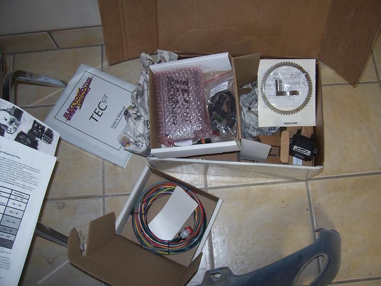
Here's a few pics of the stuff:
The whole she-bang:
Trigger wheel:

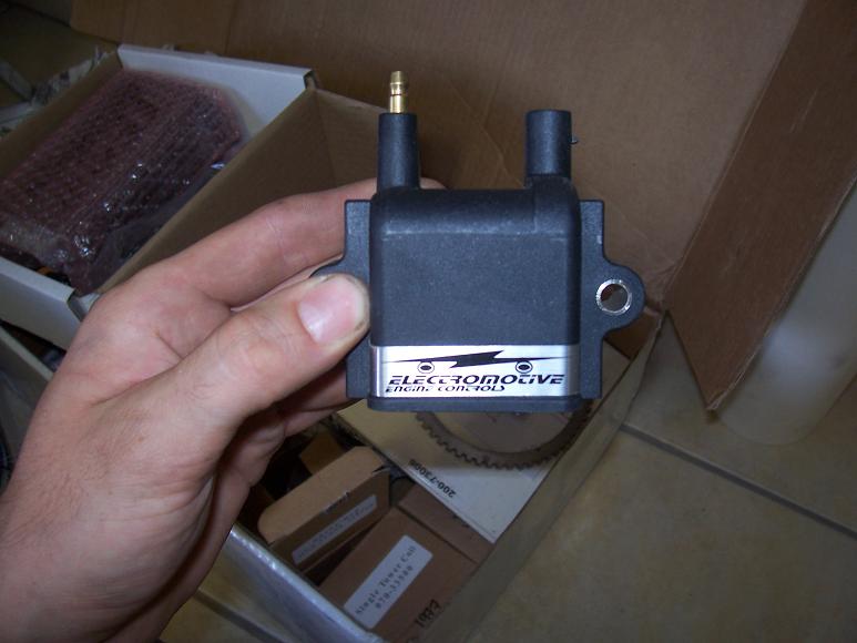
Coil:
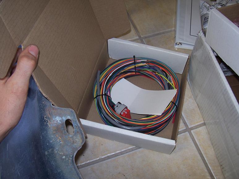
Harness:
I'll begin taking the car apart on the weekend, possibly late in the week, and see where it takes me.
Any advice on positioning of the trigger wheel? As in, with the engine at TDC the *insert answer here* tooth should be at the mag sensor?
Haven't throughly read the instructions but if someone's got a leg up on that it would help
Just cracked open the boxes and snapped some quick pics.
Looks as though I'll be needing to make an adapter to mate the trigger wheel to the main pulley as it appears to be a significantly larger diameter.
Here's a few pics of the stuff:
The whole she-bang:
Trigger wheel:
Coil:
Harness:
I'll begin taking the car apart on the weekend, possibly late in the week, and see where it takes me.
Any advice on positioning of the trigger wheel? As in, with the engine at TDC the *insert answer here* tooth should be at the mag sensor?
Haven't throughly read the instructions but if someone's got a leg up on that it would help


You can buy wheels of different diameter. And wheels with solid centers that may, or may not, be easier to mount to your pulley as you see fit. Might be easier than trying to make what you have work. Just a suggestion.
Page 16 of the manual outlines how to setup the trigger sensor and wheel. It's pretty straight forward.
Curious if the Electromotive coil is the same as this one that 034 Motorsport sells for about half the price.
http://www.034motorsport.com/product...products_id=39
Page 16 of the manual outlines how to setup the trigger sensor and wheel. It's pretty straight forward.
Curious if the Electromotive coil is the same as this one that 034 Motorsport sells for about half the price.
http://www.034motorsport.com/product...products_id=39
Thread Starter
Joined: May 2003
Posts: 7,831
Likes: 2
From: Hagersville Ontario
Thanks for the suggestions Ludwig.
The wheel isn't as far off as I thought after holding it up to the pulley. My original plan was to use the A/C compressor section of the main pulley to attach the ring. I'd measured the pulley before ordering the gammot and agreeed that 5 1/2" would work. But after talking with them, I found they had a bolt on type kit for FD's......and in my infinite wisdom I thought "well, maybe it'll save me some work?"..................it'll more then likely make more haha
The coils are probably the same since everything is re-sold nowadays. Haltech flogs LS1 coils for $95/ea rx7store sells ebay manifolds for a large mark up.....wouldn't surprise me if those coils were the same. Although, I'm not sure exactly what mine cost because they were part of the entire package.
The wheel isn't as far off as I thought after holding it up to the pulley. My original plan was to use the A/C compressor section of the main pulley to attach the ring. I'd measured the pulley before ordering the gammot and agreeed that 5 1/2" would work. But after talking with them, I found they had a bolt on type kit for FD's......and in my infinite wisdom I thought "well, maybe it'll save me some work?"..................it'll more then likely make more
hahaThe coils are probably the same since everything is re-sold nowadays. Haltech flogs LS1 coils for $95/ea rx7store sells ebay manifolds for a large mark up.....wouldn't surprise me if those coils were the same. Although, I'm not sure exactly what mine cost because they were part of the entire package.

Thread Starter
Joined: May 2003
Posts: 7,831
Likes: 2
From: Hagersville Ontario

Trending Topics
BTW, I answered you post on EFI-101. And then promptly chased you over hear to see if you were making any posts about the install. Best of luck. I have a TEC-3r sitting here waiting to go in my FD if I ever get the motivation. I looked to Electromotive for the same reasons as you. Wanted the best in ignition accuracy.
Thread Starter
Joined: May 2003
Posts: 7,831
Likes: 2
From: Hagersville Ontario
I see!
Thanks, after reading the manual and finding the "rotary type" injection wiring schematic it started to make sense.
Thats one thing I do like about the unit thus far, ignition wiring setup and injection setup for rotary's are covered very simply and very straight forward. Haltech has a decent manual and all, but I went through a bit of guess work and research on the forum here to really make sure it was how it should be. But really after reading the TEC-GT manual there's not alot of questions (BTW you can quote me on that when in three weeks when I have 600 questions )
)
Thanks, after reading the manual and finding the "rotary type" injection wiring schematic it started to make sense.
Thats one thing I do like about the unit thus far, ignition wiring setup and injection setup for rotary's are covered very simply and very straight forward. Haltech has a decent manual and all, but I went through a bit of guess work and research on the forum here to really make sure it was how it should be. But really after reading the TEC-GT manual there's not alot of questions (BTW you can quote me on that when in three weeks when I have 600 questions
)
The fact that the Electromotive package includes the ignition, I think, simplifies the install process. IMO Haltech gets itself in trouble with the fact that it is so flexible.
Anxious to hear your thoughts on the system once you get it up and running.
Anxious to hear your thoughts on the system once you get it up and running.
Funny that I'm reading that as I'm comparing pan gaskets
Hadn't noticed that portion until I looked at the parts this morning, yesterday I'd compared dimensions to see if I could run the FC waterpump etc...
My thought is now to machine down the gasket surface on the FD front cover approx. 1/8, then make an adapter to bolt to the FD cover with tapered heads (flush fit) and drill/tap for the FC pattern, but I'm not entirely sure it'll work yet. I also have a few more options being I'm using a pineapple aluminum pan (like adding to the pan itself rather then the front cover) but I'll ahve to dive a little deeper into it and figure it out. I do know I certainly want to use it - whether I end up swapping in an REW or not
Could also go back to a steel oil pan and perform these "mods"
https://www.rx7club.com/showthread.p...RE+front+cover
The RE/20B front cover has the same bolt pattern (pan wise) and the pics in that thread illustrate the offset vs. an FD front cover. Not *too* far off.
https://www.rx7club.com/showthread.p...RE+front+cover
The RE/20B front cover has the same bolt pattern (pan wise) and the pics in that thread illustrate the offset vs. an FD front cover. Not *too* far off.
I bought my stuff used. Guy I bought it off of said it was installed on an FC. After getting the parts out of the box I have no idea how the mag holder ever bolted to a rotary engine. The trigger wheel was welded to a hub adapter that would fit on a rotary hub but, again, I have no idea how it would actually work. My system is going on an FD and I'm too cheap to buy the FD trigger kit when I already have the basic components. So....
What I've determined I can do is machine the trigger wheel to fit the FD hub. The wheel I have has a solid center. I'll have the machinist turn the center out so it fits tight on the hub. Possibly cut two round bolt slots so that I can spin the trigger wheel on the hub for adjustment relative to the mag sensor before locking it in tight with the bolts. If I can get him to slot the wheel like that I'll do two slots about 45* long which would give me practically 360* of adjustment with the four bolt holes on the hub. Once I find where I want to lock the wheel in place I'll drill out the other two holes as regular holes which would ensure there is no way the trigger wheel would move relative to the hube. If I do that it will eliminate the need for an adjustable mag mount which would allow me to simply weld a sturdy tab to the front cover and bolt the mag sensor solid to the front cover. Since the stock FD pulley sticks out well past the hub I'll sandwich the trigger wheel between the pulleys and the hub. On an FC I would simply bolt the trigger wheel to the front of the hub on the outside of the pulleys.
That's what I am doing anyway and thought I would pass it along. Seems easier than changing front covers.
Last edited by C. Ludwig; Jul 15, 2008 at 04:36 PM.
Thread Starter
Joined: May 2003
Posts: 7,831
Likes: 2
From: Hagersville Ontario
Yeah, I thought much the same as far as mounting - but my order was a bit of a screw up.
I'd ordered it originally with the 5-1/2" universal wheel (solid center) and it would have had a nice long aluminum bar to mount the sensor. But the place I ordered it from presumed I had an FD, found the FD trigger wheel kit, and shipped it with that. I phoned after reciveing it and asked about switching to the universal, but after a little brainstorming thought swapping covers might be simple so I went ahead with the FD mounting kit.
Then I ran into the oil pan issue. But my thinking is this - even if I make the FD wheel work with my FC pulley's (thinking similarly to your idea, but I'd have to have a center adapter made to fit my wheel, and also fit around my pulley) I'm still going t ohave to visit the machine shop for at least the wheel portion, if not also the bracket portion since I'm not super skilled with welding AL. So given that I'm going to have a bill there either way, I might as well take advantage of the engineering put into the bracket/wheel they supply, and simply make an adapter for the bottom of the cover.
Also, to be honest, I've got a couple other reasons for wanting to use it. The major one being that I'm becoming incresingly disappointed with the dual belt system. Even match pairs I'm finding one will be sloppy after ~5,000kms. I'm not having any slippage trouble, but nonetheless the routing on the FD waterpump is much more ideal in my mind. Some fancy rad piping will need to be made to make up for the different outlet orientaion, but thats simple stuff thats more up my alley fabrication wise.
So here's the plan on the FD cover - machine down the gasket surface 1/8", make a 1/8" AL adpater plate, weld it across the front, drill tap for the FC oil pan. It seems that two of the six bolts actually line up, and others are quite close.
Also, the only other sna-foo switching to the FD stuff makes, is that there's a *minor* difference in the location of the keyways on the front hub vs an S5. So some marking will need to be made with the engine apart, and the indexing tab on the FD pulley will need to be gorund off so I can rotate the wheel a few degrees to properly align the trailing edge of the 11th tooth with the mag sensor.
Plus I won't have a blank CAS hole left when I'm done
So thats the route I'm planning to take, engine will come out of the car start of the week for a rebuild, and wiring the TEC will begin shortley there after.
Good deal. I know what you're saying about the belts. I like the FD belt a lot better myself. Can't wait to see your progress! I ordered a new harness this week and hope to begin wiring late next week. Just this week I decided to not use the street port engine I built for the car and am going HBP instead. Going to ship the assembly out to CLR this week for balancing and clearancing so the running, finished product is still a ways off. I figured a street port and 57-trim running 12 psi wasn't much of a test for an EMS so I decided to use up some parts I have to build something more extreme. 
Last edited by C. Ludwig; Jul 16, 2008 at 12:44 PM.
I'm planning on going with a Tec3r here eventally and was wondering what you guys are doing about the guages? are you able to reuse the stock Tach, speed and fuel? If so, how did you do it?
Thread Starter
Joined: May 2003
Posts: 7,831
Likes: 2
From: Hagersville Ontario
I'll be using all of them, minus the boost and oil pressure.
Speedo? Its mechanical, its operation isn't affected by this install
Fuel? Its entirely seperate from the stock ECU, its operation isn't affected by this install
Tach? I'll have to get back to you. The tach output of the TECgt is a sqaure wave, and I don't believe that will drive an FC's tach. I may have to purchase some type of converter to modify the signal and drive the tach. But I'll ahve to let you know as I find out. Good news though is either way I run it, I'll be able to make it more accurate then stock (I believe anyways....) given the adjustable output pulses from the TEC.
On an FD the speedo should still not be affected as its sensor is in the tranny ( IIRC)
Fuel? shouldn't be affected.
Tach, should be able to be driven directly by the sqaure wave tach output.
Rotary Enthusiast
Joined: Aug 2006
Posts: 1,216
Likes: 10
From: Melbourne FL/San Antonio TX/Okinawa Japan
http://rcmracing.org/racing/index.ph...id=25&Itemid=1
The FC tach will work.
Had lots of issues until the last reflash and injector change. Now things are looking up. (consistant 10.7/9 at 132/134mph at 27/28psi) Just installed a FJO injector driver to run the 1600cc 5 ohm injectors and a FJO 4 bar map sensor. 35psi is the goal.
Havent updated the site in a while. Different turbo, water/air intercooler, 4" exhaust, 1/2 inch fuel lines. and so on.
chuck
Thread Starter
Joined: May 2003
Posts: 7,831
Likes: 2
From: Hagersville Ontario
Hey thanks for the tips!
Some decent info on there....
Question, why did you need the FJO injector drvier? So you could run the 1600's P&H? I don't understand.
Some decent info on there....
Question, why did you need the FJO injector drvier? So you could run the 1600's P&H? I don't understand.
Rotary Enthusiast
Joined: Aug 2006
Posts: 1,216
Likes: 10
From: Melbourne FL/San Antonio TX/Okinawa Japan
For the last few months I've been running eight 2.2 ohm injectors. two injectors per driver set on 4 amps. Runs good but need more fuel so I am replacing two 1000cc injectors for two 1600cc 5 ohm injectors and want to make sure the injectors are getting all the power possible. reason for the driver. Will see if my plan works this weekend.
TIP: when creating a new bin file, the air temp is off. Make sure you turn it on or your air temp will go to a default setting.
also ignore the GPO errors.....
TIP: when creating a new bin file, the air temp is off.
Make sure you turn it on or your air temp will go to a default setting. also ignore the GPO errors.....
Thread Starter
Joined: May 2003
Posts: 7,831
Likes: 2
From: Hagersville Ontario
Great info sleeper7!
I hope my unit doesn't need a reflash - it was purchased brand new at the end of june, arrived in July. Thanks for the info! What Wintec version are you running? And any trouble with using a USB--->serial adapter on the gt?
Here's some more shots of the "progress" I've made lately.
These are on a J-spec I've torn down for a rebuild and I started mocking up thee trigger stuff.
Here the trigger wheel has been mounted on the original S5 hub. Now, the pic here the engine was rotated slightly advanced, but the second photo shows the engine position when the trailing edge of the 11th tooth is lined up with the mag sensor.

This illustrates the **minor** difference in the S5 and S6 front hubs. This little bit of advance could probably simply be taken into account when laying out the ignition table and be fine........but I'm going to explore a couple options of rotating the wheel, or rotating the hub, or repositioning the sensor slightly to make up for this extremely minor variance.
Next I'll be loading the whole engine stand with front half/stack onto the truck and taking it to the machinist. The lower front half of the front cover will recieve some milling and some additional AL to mate with the FC oil pan. Photos of that a little later.... Bear in mind, at this point I've done nothing creative, only bolting stuff to things. So far, pretty painless
EDIT: Also keep in mind the FD front cover uses a couple extra bolts that don't appear in the FC front iron. I figure the FC cover didn't leak, this one should be fine. I'll make doubley sure the gasket surface is true/flat though given that its designed around additional bolted areas.
I hope my unit doesn't need a reflash - it was purchased brand new at the end of june, arrived in July. Thanks for the info! What Wintec version are you running? And any trouble with using a USB--->serial adapter on the gt?
Here's some more shots of the "progress" I've made lately.
These are on a J-spec I've torn down for a rebuild and I started mocking up thee trigger stuff.
Here the trigger wheel has been mounted on the original S5 hub. Now, the pic here the engine was rotated slightly advanced, but the second photo shows the engine position when the trailing edge of the 11th tooth is lined up with the mag sensor.
This illustrates the **minor** difference in the S5 and S6 front hubs. This little bit of advance could probably simply be taken into account when laying out the ignition table and be fine........but I'm going to explore a couple options of rotating the wheel, or rotating the hub, or repositioning the sensor slightly to make up for this extremely minor variance.
Next I'll be loading the whole engine stand with front half/stack onto the truck and taking it to the machinist. The lower front half of the front cover will recieve some milling and some additional AL to mate with the FC oil pan. Photos of that a little later.... Bear in mind, at this point I've done nothing creative, only bolting stuff to things. So far, pretty painless
EDIT: Also keep in mind the FD front cover uses a couple extra bolts that don't appear in the FC front iron. I figure the FC cover didn't leak, this one should be fine. I'll make doubley sure the gasket surface is true/flat though given that its designed around additional bolted areas.
Thread Starter
Joined: May 2003
Posts: 7,831
Likes: 2
From: Hagersville Ontario
Well last night I prepared the FD trigger pulley to allow the TEC trigger wheel to be rotated on it (ie. ground off that tab)
But it should be noted that the actual difference in pulley's between S5 and S6 is notable. Looking at the pulleys the difference seems extremely minimal, but when you mount it all up....its pretty big.
I could line the rotor up at a visual TDC, and find my trigger wheel lined up on the trailing edge of the 10th tooth. One tooth, no biggie yes? Well if my math is correct, one tooth on a 60 tooth setup = 6 degrees. So if you left it this way and ran true timing numbers - you'd be 6 degrees advanced across the board.
Wiring coming soon....
Finally went to work on my FD. Here is an in-progress harness pic. Just need to terminate it. Still waiting on the engine internals to come back so it will be a while before I actually get to play with the ECU. Dropped a dummy keg in the engine bay to help with the harness assembly and locating the coils.


The sleeve and heat shrink comes from McMaster-Carr. They're Raychem products. The labels are made by printing the script off the computer and then sticking them under clear heat shrink. The clear shrink has a bit of silicone in it so it seals and the paper labels stay nice and legible.
I've been taking pictures this year of the harnesses I've built and plan to put together a blog about constructing quality harnesses. It's sad to me that so many people a) are scared of wiring a standalone, and b) when they do it 90% of the people do it poorly and that poor install leads to problems and unjust frustration with the system. Not sure when the blog will happen but I'd like to have it up by the end of the year.
And sorry for whoring up your thread. I just thought I'd drop my Tec3r learning experience in here with your's.
Thread Starter
Joined: May 2003
Posts: 7,831
Likes: 2
From: Hagersville Ontario
Thanks for the info, no apology needed - its the TEC install thread, not just exclusively mine...plus with everything going on with me lately this has been pushed back a little further on the priorities so its good that someone's making progress
Plus its nice to have a couple different builds/people so info can be shared and given between them for a better result in the end.
Plus its nice to have a couple different builds/people so info can be shared and given between them for a better result in the end.