
got a few questions about my 20b

Thread Starter
Joined: May 2003
Posts: 4,150
Likes: 0
From: CA (Bay Area)
i was disassembling a 13b block today and noticed that there is an allen bolt when my oil pressure sensor should be on a 20b (vs 13b).
also the sensor next to it is what? coolant temp? i thought the coolant temp sensor was in the thermostat housing?
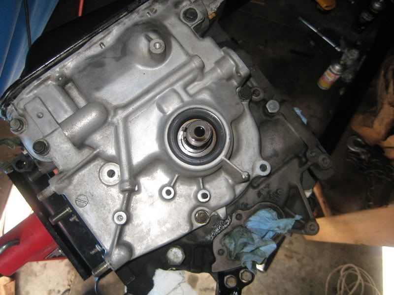
lastly... do i need to switch over to the FD front cover? the fd one has magnetic pickups, and the 20b one has the round thing which im forgetting the name of. any advice? are there other differences between the FD and 20b front covers that i need to be aware of ? thanks. -heath
also the sensor next to it is what? coolant temp? i thought the coolant temp sensor was in the thermostat housing?
lastly... do i need to switch over to the FD front cover? the fd one has magnetic pickups, and the 20b one has the round thing which im forgetting the name of. any advice? are there other differences between the FD and 20b front covers that i need to be aware of ? thanks. -heath
Originally Posted by RotorMotor
i was disassembling a 13b block today and noticed that there is an allen bolt when my oil pressure sensor should be on a 20b (vs 13b).
also the sensor next to it is what? coolant temp? i thought the coolant temp sensor was in the thermostat housing?
lastly... do i need to switch over to the FD front cover? the fd one has magnetic pickups, and the 20b one has the round thing which im forgetting the name of. any advice? are there other differences between the FD and 20b front covers that i need to be aware of ? thanks. -heath
20b cover you will need to use the CAS that came with the engine. The fd cover uses the trigger wheel. The fd power steering A/C bracket needs to have one hole drilled if your going to use the 20b cover. 20b cover matches the drill holes for the oil pan. You will have to drill a couple holes in the oil pan to match with the fd cover. I guess the biggest advantage with going with the fd cover and trigger wheel setup is, you don't have to worry about the crank angle sensor going bad (more electrical parts). Plus you get to use the fd vacuum chamber to control vacuum solenoids if you wish. If you use the fd cover, you will also have to use the fd front pulley boss. It has those two little notches to align the trigger wheel.
Extra credit

Both oil pumps are the same and will fit either one.
Thread Starter
Joined: May 2003
Posts: 4,150
Likes: 0
From: CA (Bay Area)
Originally Posted by t-von
are you saying that the 13b block had the allen bolt? I've never seen this allen bolt on any 13b. The 20b's have the allen bolt (Mine does). My guess is that the Cosmo sedan either didn't have an oil pressure gauge or the sender was in a different location.

Originally Posted by t-von
20b cover you will need to use the CAS that came with the engine. The fd cover uses the trigger wheel. The fd power steering A/C bracket needs to have one hole drilled if your going to use the 20b cover. 20b cover matches the drill holes for the oil pan. You will have to drill a couple holes in the oil pan to match with the fd cover. I guess the biggest advantage with going with the fd cover and trigger wheel setup is, you don't have to worry about the crank angle sensor going bad (more electrical parts). Plus you get to use the fd vacuum chamber to control vacuum solenoids if you wish. If you use the fd cover, you will also have to use the fd front pulley boss. It has those two little notches to align the trigger wheel.
also can you tell me more about the vacuum chamber in relation to the FD front cover? is there just no place to mount it on the 20b one? is there not a vacuum chamber (and for that matter a pressure chamber) on the 20b... there are a bunch of solenoids to control the turbo so i assumed i had taken them off and thrown them at the bottom of my parts box
. thanks as always, heath
Originally Posted by RotorMotor
also can you tell me more about the vacuum chamber in relation to the FD front cover? is there just no place to mount it on the 20b one? is there not a vacuum chamber (and for that matter a pressure chamber) on the 20b... there are a bunch of solenoids to control the turbo so i assumed i had taken them off and thrown them at the bottom of my parts box . thanks as always, heath
. thanks as always, heathThe vacuum chamber wont fit the 20b front cover since the CAS is in that location. Since the Fd cover uses the trigger wheel, Mazda changed the design of the cover in that location to allow for the vaccum chamber. Call it taking advantage of what could have been wasted space.
 Anyways most don't even worry about the vaccum chamber cause it's main purpose in the 13brew was to speed the reation time of the sequential turbo charging system components. I was just throwing that out there. You can mount that vaccum chamber anywhere in the engine bay if you decide you want to use it with the 20b cover.
Thread Starter
Joined: May 2003
Posts: 4,150
Likes: 0
From: CA (Bay Area)
ah thanks very much for the explanation. at the moment im planning on *attempting* to run a simplified sequential setup so ill most likely run into that problem when i start assembling everything. at the moment i still have no idea where everything is going to go in the engine bay as i have a pettit frame and may need to retain an airpump, plus fit the intakes somwhere, as well as trying to keep all of the factory accesories. ill most likely need to make some sacrifices when every square inch of the bay is packed. 
Thread Starter
Joined: May 2003
Posts: 4,150
Likes: 0
From: CA (Bay Area)
ok time to reopen this thread since im further into my project and have more unanswered questions than ever! im not gonna claim to be the sharpest tool in the shed, so before i do anything irreversible, it's probably best to run it by you fine gentlemen who have "been there and done that"
1: ive got the FD front cover test fitted and im ready to drill the oil pan for the new bolt holes, however, the location of a few of the required holes lie over raised areas of the oil pan. should i skip these bolt holes or attempt to hammer the pan flat?? and tips?

2: The FD front cover has a different location and different size (smaller) for the primary turbo oil return line. My only thought is to take the two extension tubes to a shop and have them cut the 20b tube to size, remove the end flanges from both, and braze/weld the FD flange to the shorter 20b tube so that it can bolt up to the FD front cover. However, this significantly reduces the oil passageway for the primary turbo. This is the least drastic solution however i dont want to cook the primary or slow it down by not being able to eject the proper amount of oil back out.

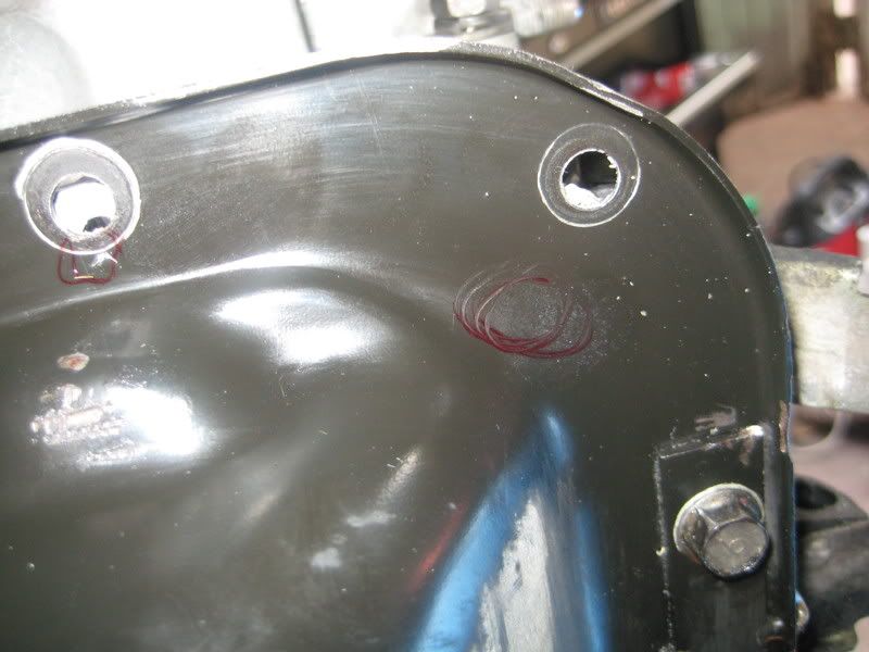
3. (more of an observation) The FD front housing has two additional bolt holes along the sealing edge at the 4 o-clock and 8 o-clock positions in my picture). i assume it will seal ok without them and that i should fill both with sealant. are the FD torque values for these bolts is ok?
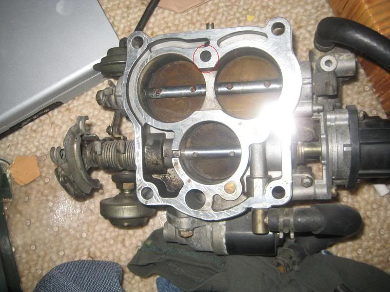
4. On the 20b throttle body there is a hole at the top above the secondary intake runners but below the idle adjust screw port. it passes from one side of the TB to the other (and the gasket that was on the back of the TB covered this port. What is its function and should it remain covered by the new gasket im making?
5. This one i feel REALLY stupid asking, but ive already shown that i cant get too far without the support of this forum so here it goes:
Im trying to setup an airpump (because i live in smog **** CA) but im having a hard time understanding how this is setup stock. There only seems to be one passage to the airpump (on the back of the housing with a nipple) which connects to the trapezoidal passage on the LIM. as far as i can tell it ONLY connects to this passage. The circular passage is for port air injection and normally houses a circular check valve. the large upper hole is a dead end, two of the smaller round ones go to the intake runner thats behine them, and the third goes through the LIM to a vacuum nipple.
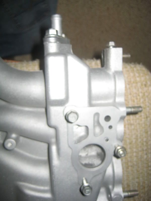
OK i understand this so far, but then looking at the air assembly that bolts up i have become very confused as to its operation. I understand the circular plunger is controlled by vacuum (or solenoid fed vaccuum). i dont know what the upper chamber is for or how it works, i dont know what the connector is for, but it appears to move a TINY solenoid that uncovers a very small hole that connects to the air pump port. i still cant figure out how the air pump is supposed to do its job with the cats as the only inlet is from that trapezoidal port. basically i need some help in understanding the functionality of this system, as i cant seem to uncover enough info explaining how it works in detail.

Thanks guys, im lost without you -Heath
1: ive got the FD front cover test fitted and im ready to drill the oil pan for the new bolt holes, however, the location of a few of the required holes lie over raised areas of the oil pan. should i skip these bolt holes or attempt to hammer the pan flat?? and tips?
2: The FD front cover has a different location and different size (smaller) for the primary turbo oil return line. My only thought is to take the two extension tubes to a shop and have them cut the 20b tube to size, remove the end flanges from both, and braze/weld the FD flange to the shorter 20b tube so that it can bolt up to the FD front cover. However, this significantly reduces the oil passageway for the primary turbo. This is the least drastic solution however i dont want to cook the primary or slow it down by not being able to eject the proper amount of oil back out.
3. (more of an observation) The FD front housing has two additional bolt holes along the sealing edge at the 4 o-clock and 8 o-clock positions in my picture). i assume it will seal ok without them and that i should fill both with sealant. are the FD torque values for these bolts is ok?
4. On the 20b throttle body there is a hole at the top above the secondary intake runners but below the idle adjust screw port. it passes from one side of the TB to the other (and the gasket that was on the back of the TB covered this port. What is its function and should it remain covered by the new gasket im making?
5. This one i feel REALLY stupid asking, but ive already shown that i cant get too far without the support of this forum
so here it goes:Im trying to setup an airpump (because i live in smog **** CA) but im having a hard time understanding how this is setup stock. There only seems to be one passage to the airpump (on the back of the housing with a nipple) which connects to the trapezoidal passage on the LIM. as far as i can tell it ONLY connects to this passage. The circular passage is for port air injection and normally houses a circular check valve. the large upper hole is a dead end, two of the smaller round ones go to the intake runner thats behine them, and the third goes through the LIM to a vacuum nipple.
OK i understand this so far, but then looking at the air assembly that bolts up i have become very confused as to its operation. I understand the circular plunger is controlled by vacuum (or solenoid fed vaccuum). i dont know what the upper chamber is for or how it works, i dont know what the connector is for, but it appears to move a TINY solenoid that uncovers a very small hole that connects to the air pump port. i still cant figure out how the air pump is supposed to do its job with the cats as the only inlet is from that trapezoidal port. basically i need some help in understanding the functionality of this system, as i cant seem to uncover enough info explaining how it works in detail.
Thanks guys, im lost without you
-Heath
Thread Starter
Joined: May 2003
Posts: 4,150
Likes: 0
From: CA (Bay Area)
ok#1 is resolved... hammered those areas flat, and the pan fits ok. stupidly i drilled the holes for the bolts first BEFORE i hammered (wanted to know how much to flatten to clear the bolt heads) but i neglected to realize that after hammering the holes would wander a bit, so i had to do a little redrilling, but it will work ok. if i were to do it over i would do it the other way around, but it definitely works now. ill post some pics of the pan so the next guy will know where and how much to flatten first. two areas needed to be flattened and one area needed to be *slightly* indented to clear the bolt head.... other than that its a straight shot with a simple template and a drill.
anyone have thoughts on the others (mainly #4 and #5).
anyone have thoughts on the others (mainly #4 and #5).
Trending Topics


Joined: Mar 2001
Posts: 31,851
Likes: 3,239
From: https://www2.mazda.com/en/100th/
4: i think thats the idle speec screw? i dunno if it was covered by the old gasket, then keep it that way.
5: the air injection pretty much works the same on all of em (i think fd might be simpler or backwards or something) under about 2500-3000rpms the air pump air goes into that big round hole in the manifold, and eventually makes it to the exhaust ports. under transitions and cruise it goes out the back to the cats, and the rest of the time the air is just dumped. so there is 2 diaphrams, 1 switches between dumping air and letting it into the valve, and 2 decides weather it goes to the exhaust ports or the cat.
5: the air injection pretty much works the same on all of em (i think fd might be simpler or backwards or something) under about 2500-3000rpms the air pump air goes into that big round hole in the manifold, and eventually makes it to the exhaust ports. under transitions and cruise it goes out the back to the cats, and the rest of the time the air is just dumped. so there is 2 diaphrams, 1 switches between dumping air and letting it into the valve, and 2 decides weather it goes to the exhaust ports or the cat.
Thread Starter
Joined: May 2003
Posts: 4,150
Likes: 0
From: CA (Bay Area)
4: i think thats the idle speec screw? i dunno if it was covered by the old gasket, then keep it that way.
5: the air injection pretty much works the same on all of em (i think fd might be simpler or backwards or something) under about 2500-3000rpms the air pump air goes into that big round hole in the manifold, and eventually makes it to the exhaust ports. under transitions and cruise it goes out the back to the cats, and the rest of the time the air is just dumped. so there is 2 diaphrams, 1 switches between dumping air and letting it into the valve, and 2 decides weather it goes to the exhaust ports or the cat.
5: the air injection pretty much works the same on all of em (i think fd might be simpler or backwards or something) under about 2500-3000rpms the air pump air goes into that big round hole in the manifold, and eventually makes it to the exhaust ports. under transitions and cruise it goes out the back to the cats, and the rest of the time the air is just dumped. so there is 2 diaphrams, 1 switches between dumping air and letting it into the valve, and 2 decides weather it goes to the exhaust ports or the cat.
also i dont think that hole is for the idle screw, the idle screw hole sits above it and is connected via a semicircle channel which runs from the top of the TB to the bottom intake runner (bypassing the secondary butterflies). im still not sure what that hole is used for. the gasket that came on my TB did not appear stock so it may have been set up differently then stock should be. -heath
Joined: Mar 2001
Posts: 31,851
Likes: 3,239
From: https://www2.mazda.com/en/100th/
Thanks. Do you know how exactly that valve diverts the air directly to the cats though? the only connection to the nipple on the back of the UIM (which feeds the cat directly) is the trapezoidal port. the matching port on the air control valve (lower left in my picture) is basically a dead end. the only passage that exists between that area and the main cavity cant be larger than 1/8", and appears to be controlled by a solenoid which moves a plunger which covers/uncovers that tiny hole. is that the only volume of air thats fed to the cats??
also i dont think that hole is for the idle screw, the idle screw hole sits above it and is connected via a semicircle channel which runs from the top of the TB to the bottom intake runner (bypassing the secondary butterflies). im still not sure what that hole is used for. the gasket that came on my TB did not appear stock so it may have been set up differently then stock should be. -heath
also i dont think that hole is for the idle screw, the idle screw hole sits above it and is connected via a semicircle channel which runs from the top of the TB to the bottom intake runner (bypassing the secondary butterflies). im still not sure what that hole is used for. the gasket that came on my TB did not appear stock so it may have been set up differently then stock should be. -heath
i'm guessing on the idle screw, i guess i could go find mine and have a look
Thread Starter
Joined: May 2003
Posts: 4,150
Likes: 0
From: CA (Bay Area)
aha! thanks that clarifies it. i was under the impression that a much larger volume of air was sent to the cats... its seems that nearly all is sent through the port air injection... so actually it seems that (assuming youre not gonna use the port air injection, which i wouldnt be) the cat is nearly rendered useless? hmm i need to rethink my emissions now, its a totally different ballgame! -heath

Thread
Thread Starter
Forum
Replies
Last Post
Adaptronic S5 Turbo PNP Unit questions
_Tones_
Adaptronic Engine Mgmt - AUS
10
May 25, 2021 05:37 AM
Nosferatu
2nd Generation Specific (1986-1992)
7
Sep 5, 2015 02:13 PM