When you click on links to various merchants on this site and make a purchase, this can result in this site earning a commission. Affiliate programs and affiliations include, but are not limited to, the eBay Partner Network.
Went to the rotary spirit event at NJMP this past weekend. my GOD was it hot. Car ran warm the whole way there. roughly 195-200*F the whole way. That was with the heater core wide open. Great time catching up with friends!
Still trying to figure out the timing of the engine. I recently added 15* of timing for ***** and giggles in the driveway and it does not heat up nearly as fast and it cools down way faster. I'm guessing I'm still somewhat retarded timing wise....What are my best methods for getting this closer? I'm hesitant to pull the crank hub but its starting to look more that way.
my car runs at 195-205 on the hwy but I do still have the ac system. Is this high for 20b�s?
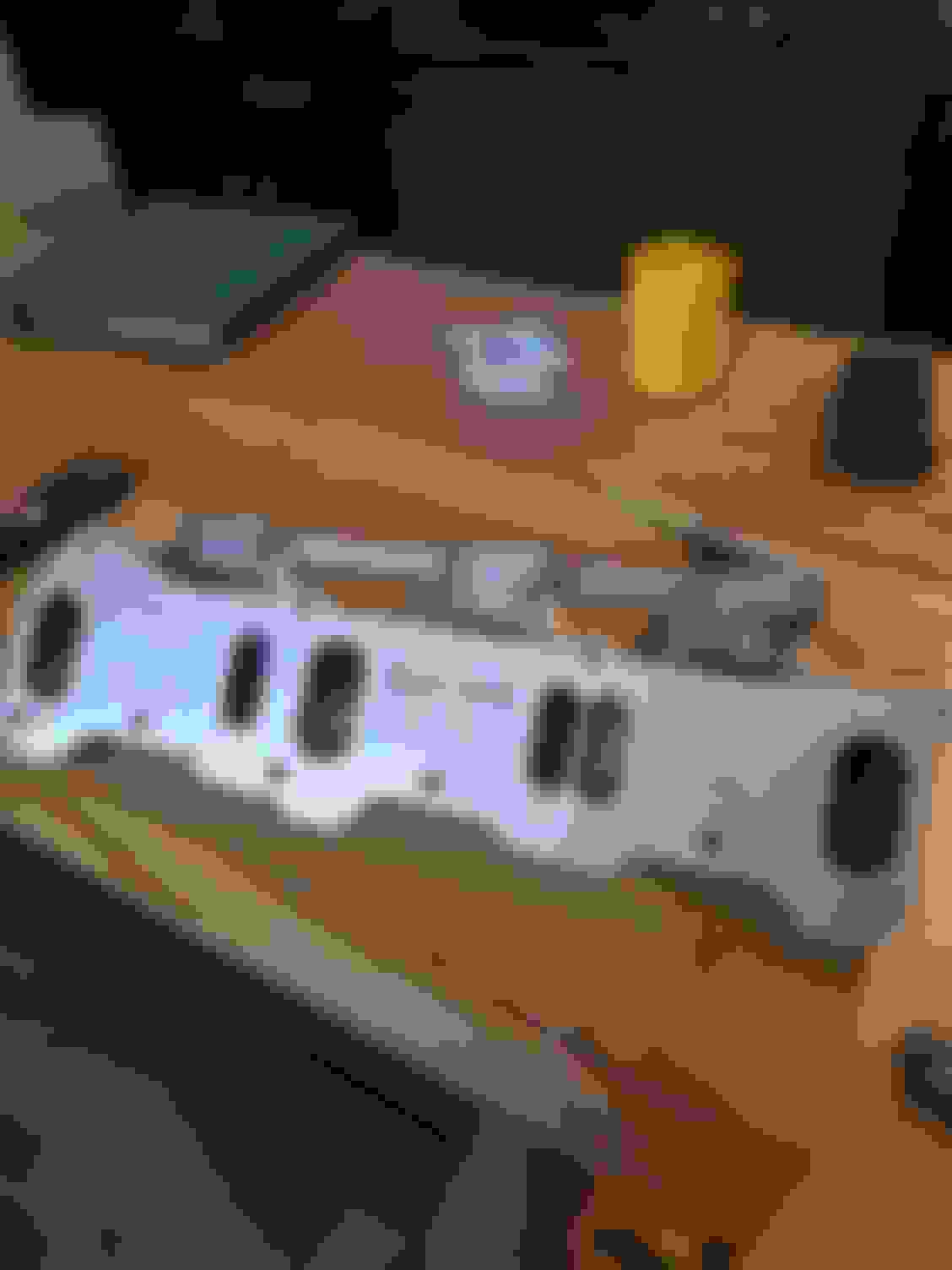
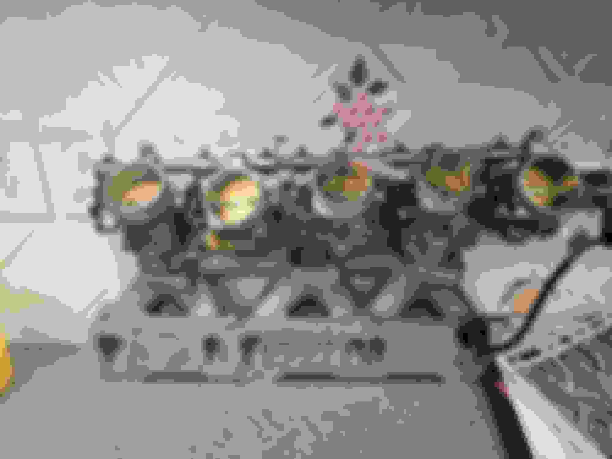
Recently placed an order for the EFI hardware LIM. I plan on using that and attaching some BMW S85 ITBs.
These can be had much cheaper and have a few benefits that should get me close.
The EFI hardware setup is $4500 or so all in.
So far I've spent $1000 on the LIM, and $200 on a row of ITBs
Benefits include a TPS integrated into the linkage system.
The throttle linkage is simple and in the middle of the rail.
Each ITB is on a roller bearing so it should be possible to cut down the main bar and space each TB accordingly, then carefully drill new holes.
The injector port is in the ITB meaning nice cool fuel being injected up high, while still retaining a close injector for idle quality.
The hardest parts here I think will be making a fuel rail. The ITBs will need an adapter to match the ports. This should be a simple 3d print. PA-CF will be the material of choice. (CF impregnated nylon)
If this doesn't last with the engine bay heat I'll see about getting them printed in a metal.
As for an air box, I want to replicate this thing as it had a wonderful harmonic noise and if I could replicate something like that I'd be ecstatic.
Last edited by driftxsequence; Jul 23, 2024 at 03:31 PM.
Things are happening. 3d printer and prototyping an adapter currently. Once I have this working I'll be printing it out of cf reinforced nylon, same thing OEMs are using.
Using fusion 360 I took an image of the flanges and copied them into CAD.
First attempt was a fail. The orientation was way off. Second attempt looks like I have it right, but the filament got way too warm and started getting weirdly stringy. Each of these take roughly 6 hours at default speeds on an ender 3....so hopefully by end of tomorrow I can mount. Up 3 ITBs and move onto phase 2.
Man it's been a frustrating weekend getting this thing to print successfully. Got the CR touch setup, once I did that with new firmware they must have changed settings because now I keep getting a clogged tip. The print started absolutely perfect and as you can see it devolved into a mess at the top. Google is saying it's clogging up? Stock hot end currently.
Got the printer dialed in today. First crisp print. Solid infill, has a nice bit of weight for PLA. I just kind of guessed the angle of the flanges, and I guessed wrong. Looks like it needs another 5-10� before it lines up properly or just ream the holes out a bit larger. That might be the easier way to go.
There's a new iteration cooking up that tilts the ITB so the injector shoots straight down.
Pretty close with the adapter. My flange is still a little off...but I think I can just open the holes up and call it good enough.
I doubt this will be my final iteration.
The rear most ITB sets the rest in place as it is what holds the rotating bar in place with a screw. The rest of the attachments just clamp down. As it sits, all I need to do is drill a hole for the middle ITB and chop down the excess.
I've enjoyed watching your updates on FB, those ITBs are gonna be awesome!
I appreciate the kind words!
I'm at a cross road. I want to get DBW setup but getting a pedal, DBW controller, making the proper actuator bracketry and piping that into the Megasquirt...just seems a bit daunting right now. Its looking like a custom throttle cable with a 3d printed bracket will be the quickest and dirtiest solution. That seems to be the way it goes around here...never done right. just good enough engineering wise lol. Looks like I will need a longer cable that will come down tight to the block, and then point upward, as the lever has to pull downward to open. I've never messed with this area so I'm hoping someone can chime in or point me to an article describing how the radius or whatever of the throttle pull affects how quickly it opens compared to pedal travel. my gut tells me having the two linkages the same throw is not idea and it needs to be a one is larger than other situation.
After some googling I've come to the conclusion that I need to measure (sharpie the cable) the distance the cable travels from closed to open. This will tell me how far the pedal throw is. There is a whole lot of math about the ratio between the radius of the linkage, and the pedal to the center point of the pedal...I dont think I need to get that deep into the weeds. I just need to know the length of throw I currently have, and be in that ball park when I create the new setup.
What I just thought about is, I can attempt to re-use one of the extra BMW throttle body linkages since I have 2 extra of these laying around and I'll have extra bar stock. I can 3d print a roller bearing holder , stick the rod and lever on there and weld a little adapter that goes to a normal throttle cable mount.
Low motivation day.. Work has been draining me. Anyway I created a quick injector block off plug in fusion 360 for the ITBs. I won't need this right away, so I a quick side profile, then revolve it to make a circle and voila!
I need to remake the head 1mm smaller so that I can sink it into the injector port more but it'll do for now.
Are you planning on having those parts milled out of aluminum after test fitting or will you try running the plastic printed parts?
I plan on using the 3d printer for as much of this as possible.
Manufacturers use PA-CF for their intake manifolds which is carbon impregnated nylon. This has a heat deflection temperature of 170*C. This should be more than plenty to hold up to the task. If OEMs use it, I think I can use it too.
Finally got off my *** and worked on the car a bit. While working with a local, we switched the car from end of injection to beginning of injection for when it fires the injectors. This seemed to have helped immensely with idle and low end hiccups. Car is running much better and needs a few more tweaks to really dial it in. Even without an idle valve it's quite happy to start up without pumping the throttle now.
Also, having been caught in two bouts of traffic recently and sweating the coolant temperature, I finally hacked up my nice new radiator to fit the brushless SPAL that's been on the shelf for nearly a year.
I trimmed the top and bottom brackets that the radiator had, so it could be flush mounted and it just barely fits. One of the supports required some clearance for the FFE trigger but it clears.
Wiring it up should be pretty simple. Power direct to alternator, ground, and a PWM signal to the megasquirt. I think I was smart enough to run a wire in the harness before closing it up....guess we'll find out tomorrow.
Last edited by driftxsequence; Apr 9, 2025 at 12:09 AM.
Can you clarify what you mean when you say "caught in two bouts of traffic recently and sweating the coolant temperature"?
You was stuck in traffic and coolant got a little higher than you wanted? Do you remember what the temp was and what did you do to bring it down?
Yes that's correct. Typically I turn on the cabin heat full blast with windows down, and if need be, I'll shut the car off if it's bumper to bumper traffic. turn off recirculating air for maximum cooling effect.
Last night I was able to successfully hook up the new fan and test it. It moves WAY more air than the old fan. I'm looking forward to stressing testing it this weekend.
Last steps are to mount it and add a small buffer so it doesn't chafe the radiator...any suggestions?
Would you be able to share the model number for that SPAL fan?
I've been running the Taurus fan for years and very happy with its performance at idle. However, I think the integrated shroud is causing restriction at speed. I've noticed sometimes that on the highway on a hot summer day the fan will activate. This is after adding flaps. Plus PWM would be really nice.