When you click on links to various merchants on this site and make a purchase, this can result in this site earning a commission. Affiliate programs and affiliations include, but are not limited to, the eBay Partner Network.
The port capped off on the plenum is the vac source for the BOV. Because I was running the engine without the IC plumbing for leak checks after first startup, I just put a compression cap on it.
The BAC can be flipped either way, the bolt holes are symmetric. Honestly, I didn't realize it was backwards until after a few months when someone pointed it out.
The coolant in/out comes off of the BAC with 2 screws. Just toss em.
For the ports on the block, I drilled out the one in the water pump housing for the coolant temp sender for a gauge.
The rear one, I slipped a 3/8" compression nut and ferrule over and used a plug for a metal-tight seal. This took some "massaging" in the form of a mallet and I would not recommend. It is a 10mm barb, so 10mm or 3/8" hose cap with a clamp would work. McMaster-Carr sells nice silicone caps for cheap, That's what I've used on other ports on the engine.
I finally got a chance to take the manifold apart and i see what you mean about the plenum being separate between the primaries and secondaries. I was imagining that plenum area as being open. So that complicates the sensor placement a lot. My new target is the subzero starting injection port, but its much more difficult to modify. I'll have to think about that some more.
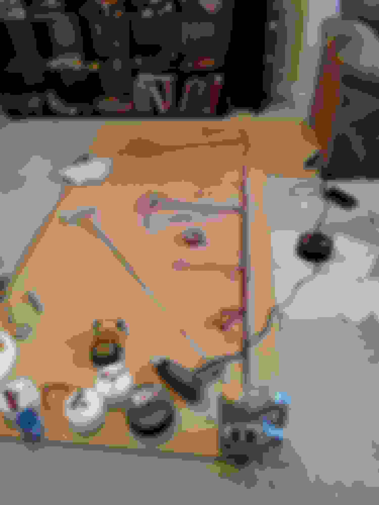
I made good progress on my pinboard over the weekend, and made a mockup harness to test fit. Good thing i did, i found several subtle changes to make.
Original pinboard layout
mockup harness
mockup installed in car
revised pinboard, palm sander works great as an eraser
I've got a lot of pics of the harness coming out of the car if anyone is interested in seeing anything specific, let me know.
Next step will be to estimate the wire bundle sizes for each leg so i can order shrink tube. Then i'll start stringing wires.
lol, i'm putting a stock FC back together, and Mazda just went nuts with all the little clips and clamps and supports for the wiring harness. the kicker is the clip for the air supply valve wire, you know, because those 2 wires can't be unsupported for 3", they needed a $15 bracket to hold em.
i was going to suggest using the JDM harness routing, as it is a little simpler, but i'm not sure it would fit with the stock intake. basically it sits on the engine the same, but since the ecu is on the other side, the big bundle comes out under the oil filter, and then the AFM/boost sensor branch is just the afm/boost sensor, so its small. for a LHD car, i would suggest the big bundle get moved to the other side of the filter, and then it just runs along the firewall, but i'm not sure the T2 intakes leave room. basically you'd avoid running the harness along the shock tower, like Mazda did with the FD
At some point in the next couple months I'll be starting on a new harness for my car... I've got all the grand ideas of tefzel, DR-25, concentric twists, Deutsch etc...
I'll be watching keenly, so please take heaps of pics. And keep up the good work!!
j9fd3s,
Coming from a racing background i love all the clips. Vibration is hell on a wiring harness, and especially an OEM harness. The Boss 302 mustang GS and WC cars originally had basically a factory harness with DTM connectors on it, the factory wires broke all time, there was almost always some intermittent electrical issue on those engines. Eventually the better off teams started running proper motorsport harnesses, but those certainly arent immune to issues.
I looked at some alternate routings, and changed up some of the breakouts, but for the most part i am going to follow the factory routing.
S2-13BT,
Sweet, be sure to ask me questions if i leave something out. Im a lot better at explaining things when i know what people are interested in.
I worked on some of the hardware modifications for this project today, I'll probably start stringing wires tomorrow once i finish up some more odds and ends on the hardware side.
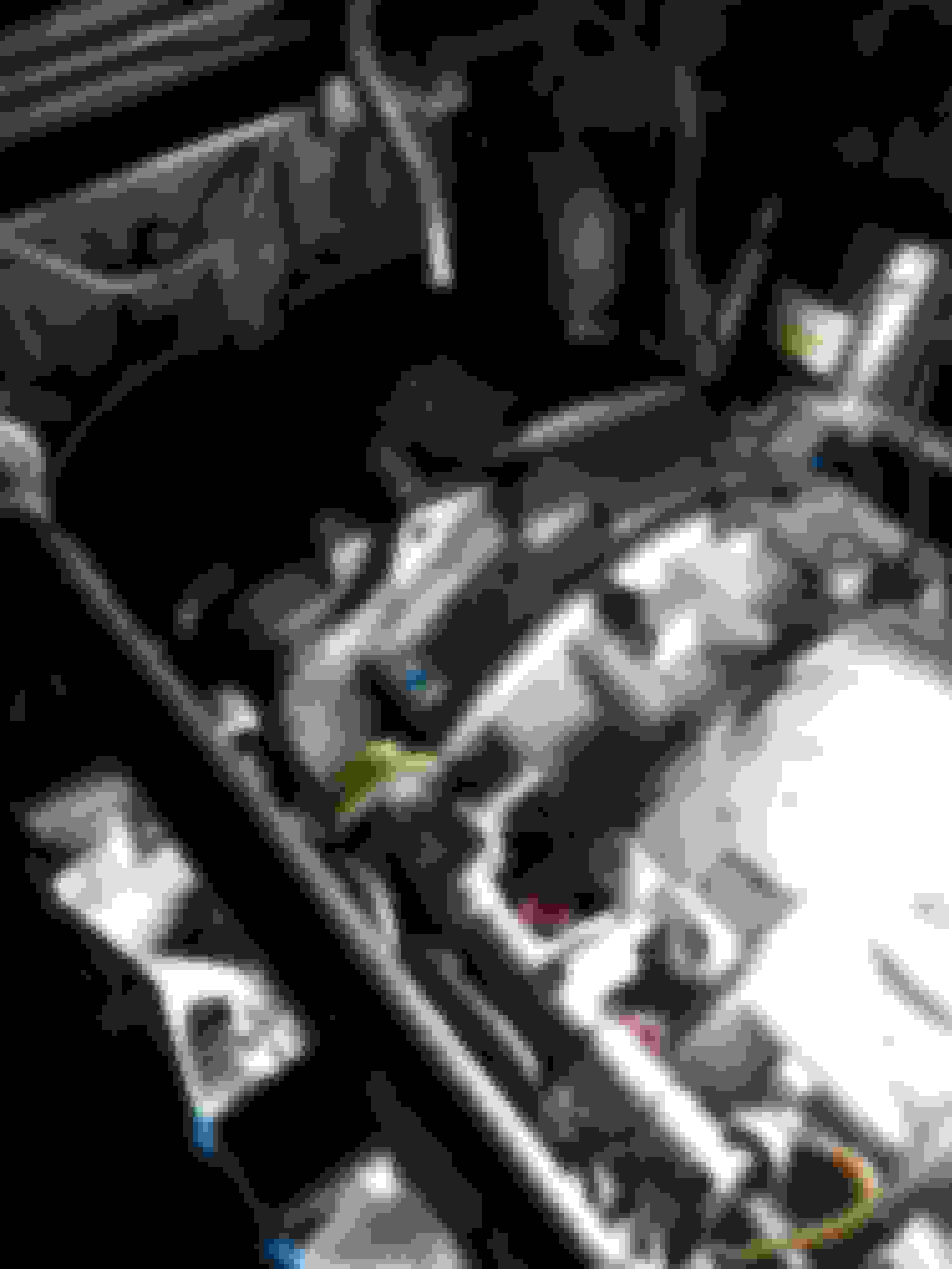
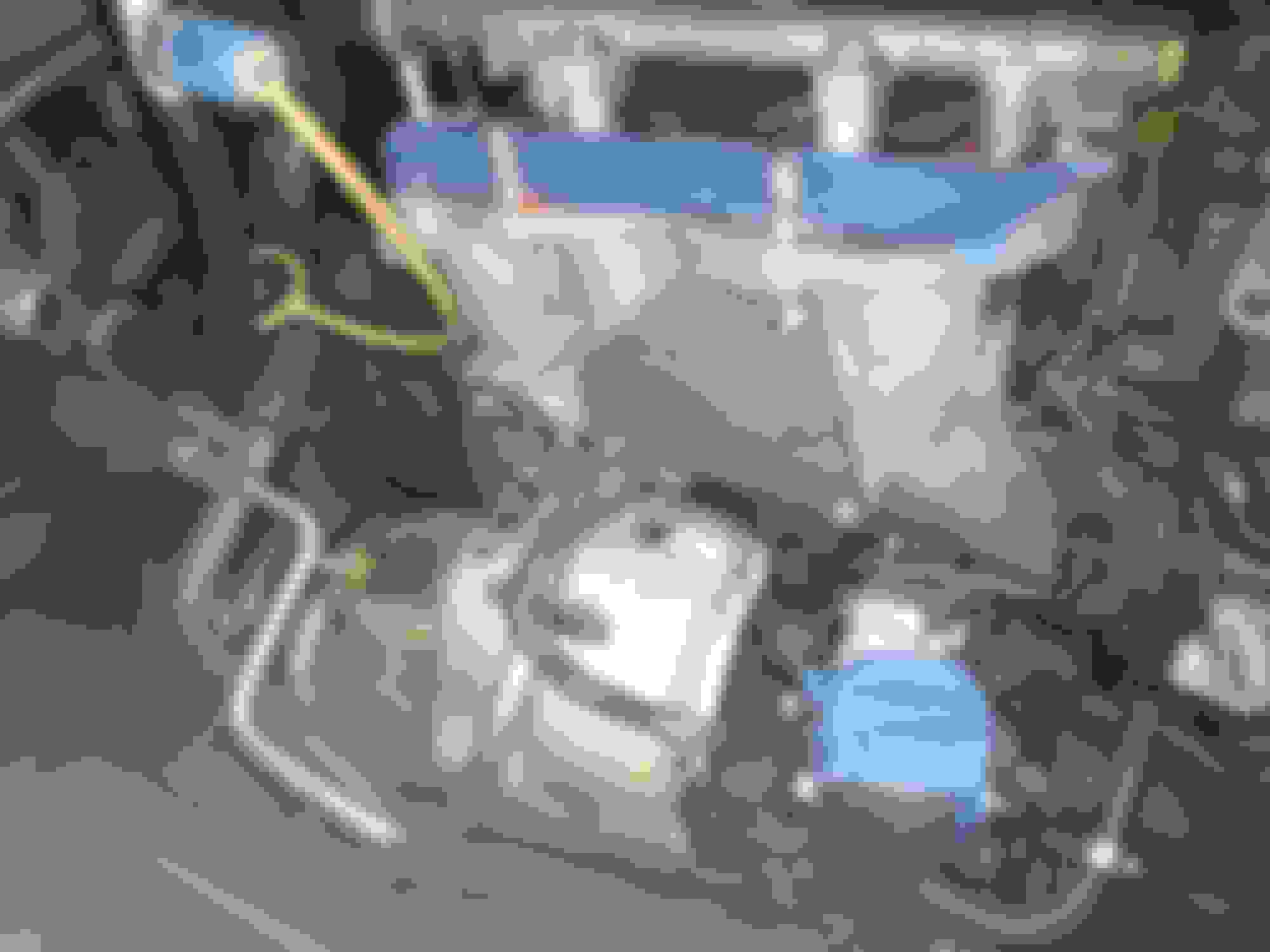
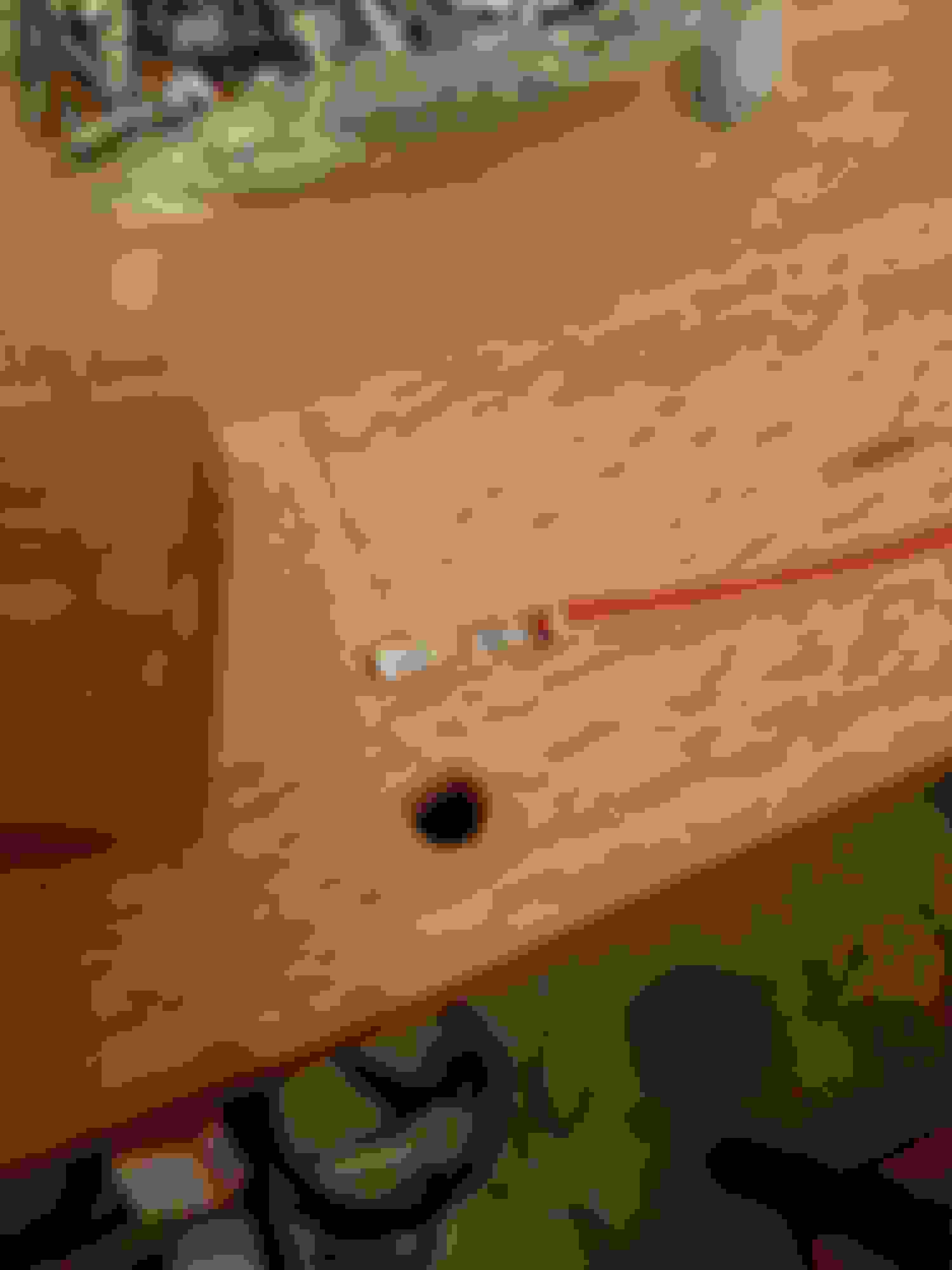
I am eliminating the coolant circuit thru the BAC valve and the throttle body. I dont ever plan to run this car in the cold so there's no concern of icing. I pulled the barb fitting out of the back of the water pump housing, and out of the rear iron. Those are simply pressed in, so they can be removed with vice grips. Unfortunately the holes are a little larger than the tap drill of a 1/8NPT. I tried tapping and plugging them with 1/8NPT plugs, but i am not super confident in them sealing since the holes are over sized. If they leak, i will drill it out to a 1/4NPT and try again. UIM coolant passage plugged
UIM coolant passage plugged
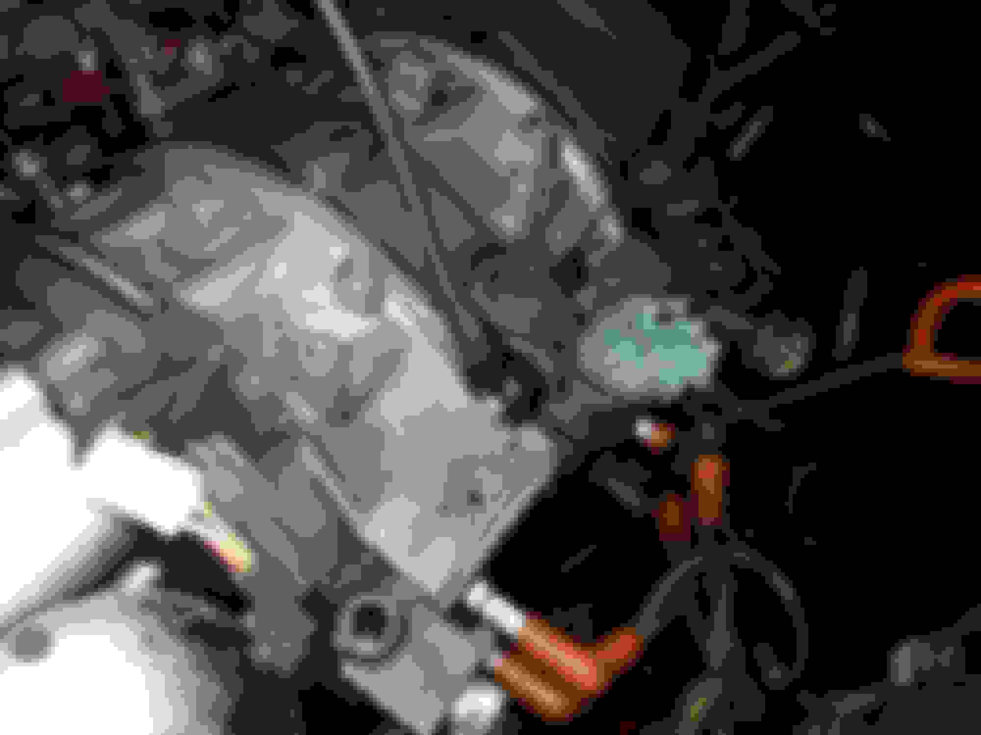
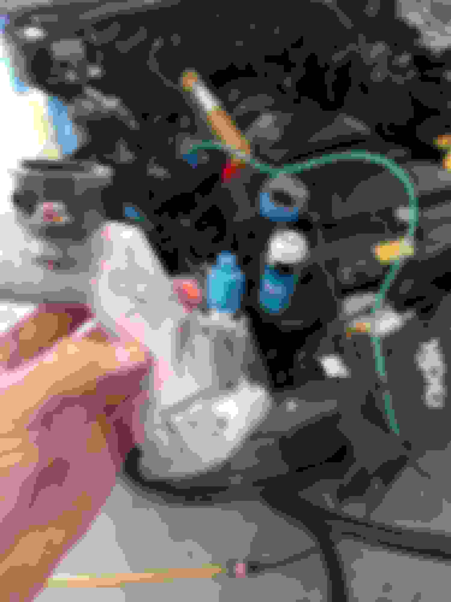
The Kulite pressure sensors i am using for fuel, water, and oil pressure have -4 AN fittings so i replaced the factory oil pressure sender with a -4 AN fitting. The stock pressure sender is a 1/8 BSP tapered thread, i used a 1/8 BSP straight thread with a sealing washer. It fit well and there was plenty of flange space, so i have no concern of using a straight fitting instead.
Oil pressure sensor fitting
The new Bosch knock sensor i want to use is intended for a M8 bolt. The factory knock sensor was an M10. The tap size of an m8 helicoil with the same pitch, is only slightly smaller than the m10, so I was able to install an m8 helicoil in the factory location. The threads are certainly loose, but it torqued up fine, i dont think this shortcut would work if it was in aluminum.
Heli-coil to fit M8 knock sensor
knock sensor
I replaced the water temp switch in the thermostat housing with a m16 to -4AN fitting. i'll need to get a picture of that tomorrow.
I also replaced the pulsation damper in the primary injector rail with a banjo bolt that has a 1/8 NPT port in the end. I have a 1/8 NPT to -4AN fitting there for fuel pressure. I really hate using NPT fittings since they are so likely to crack in the threads, but since the fitting is steel, it should be OK. NPT is super easy to work with compared to an SAE or ORB port but not nearly as nice. I'll need to get a pic of that tomorrow too.
I also installed block off plates on all the common places, except the BAC. I plan to keep that.
I was hoping to install my Bosch MAP sensor in the lower intake manifold where the sub zero starting ports are. Unfortunately i dont think that will work since theres a boss for a vacuum port right below that location that will be in the way. Im back to the drawing boards once again on where to install that... Certainly open to suggestions.
I used about 2 cans of SD-20 cleaning the engine bay. That stuff is a god send. If you're not familiar with it, its a foaming surface cleaner. its super popular in racing because it is such a versatile cleaner. Its very mild, you can wash your hands with it and i've yet to find something that it damages, but it cuts oil and grease nearly as well as brake cleaner. You can spray it all over the engine and then either wipe it off with a rag or just blow it off with an air hose. Super handy for cleaning hard to clean things like an oily wiring harness for instance.
Does anyone know how the oil filler neck is supposed to seal in the center iron? When i took mine apart, i didnt see any oring or gasket and it had certainly been leaking.
I am also struggling to find injector connectors that have the offset key. The best i've been able to find are expensive, but really crappy, Dorman replacement pig tails. I really want to find a name brand connector. I really really hate the idea of putting such crappy connectors in my nice harness.
That reminds me, i think that i finally found terminals for the FEM 01 and 02 connectors. If they are the right ones, that will let me do a much nicer job of integrating the FEM connectors into my harness. I was dreading having to use the factory wires for those connectors. I had to order 1000 of them since the only source i could find was someplace in China, so i will have lots of extras if they ever come....
Does anyone know how the oil filler neck is supposed to seal in the center iron? When i took mine apart, i didnt see any oring or gasket and it had certainly been leaking.
I am also struggling to find injector connectors that have the offset key. The best i've been able to find are expensive, but really crappy, Dorman replacement pig tails. I really want to find a name brand connector. I really really hate the idea of putting such crappy connectors in my nice harness.[/QUOTE]
its a press fit, it looks like your engine has been rebuilt, so maybe you should tap the thing out and reinstall with a little sealant?
the old school way to deal with the offset key is just to trim it off. it'll comes off with a razor blade.
j9fd3s,
Whats the give away that its been rebuilt? The previous owner said that it hadnt been, but that doesnt mean a thing. It certainly isnt a press fit anymore so i'll have to come up with something.
How come tou dont go with ID injectors and a FFE triggerkit and some decent coils when you go thru all that trouble with a motec and all those sensors, the injectors and coils made my previous engine a totally different beast, no more hotstart issues, emissions got ALOT better and it became much more crisp....and yes i know that the stock coils and injectors where ok cause i tested/had them sent for cleaning. Its just old crappy tech. the cost is there yes but the tuning time is easily cut to half since the ID comes with so much data you can prepare your ecu with. the aem smart coils/mercury coils are strong enough to get the car running even if it runs so rich its pouring gas thru your tailpipes :-)
^ +1!
New injectors and the FFE trigger make a world of difference. It also simplifies things with since it only has one VR (or Hall) sensor. Sequential ignition would also be nice, but not 100% necessary if you don't plan on running high boost. Buying new injectors with known dead times take a lot of the guesswork out of tuning, especially when trying to smooth out the staging transition for the secondary injectors. Have the dead time even slightly off can cause a lean or rich spot when they stage in/out. Really frustrating.
j9fd3s,
Whats the give away that its been rebuilt? The previous owner said that it hadnt been, but that doesnt mean a thing. It certainly isnt a press fit anymore so i'll have to come up with something.
Thanks,
in the first pic in that last post, i think you can see some sealant between the center iron and rotor housing. Mazda didn't use any sealant between the housings, except the water seals, so anything else = rebuilt/resealed.
Guys,
Thanks for the tips. For now i'm trying to avoid changing coils and injectors since i know these parts work and i'm quickly running out of money. I have protected for upgrading all of these things in my harness. My plan for now is to make it work on the new ECU and electronics, then once i've saved up some more money, i'll work on a nice engine with nicer hardware.
Good tip on the sealant. I took a closer look at the joint tonight and cant actually see any sealant. The thing that looks like squeezed sealant in the first pic is really a bur on the rotor housing. I'm still hopeful that the original owner never opened it up.... I'd hate to think what surprises await if he has.
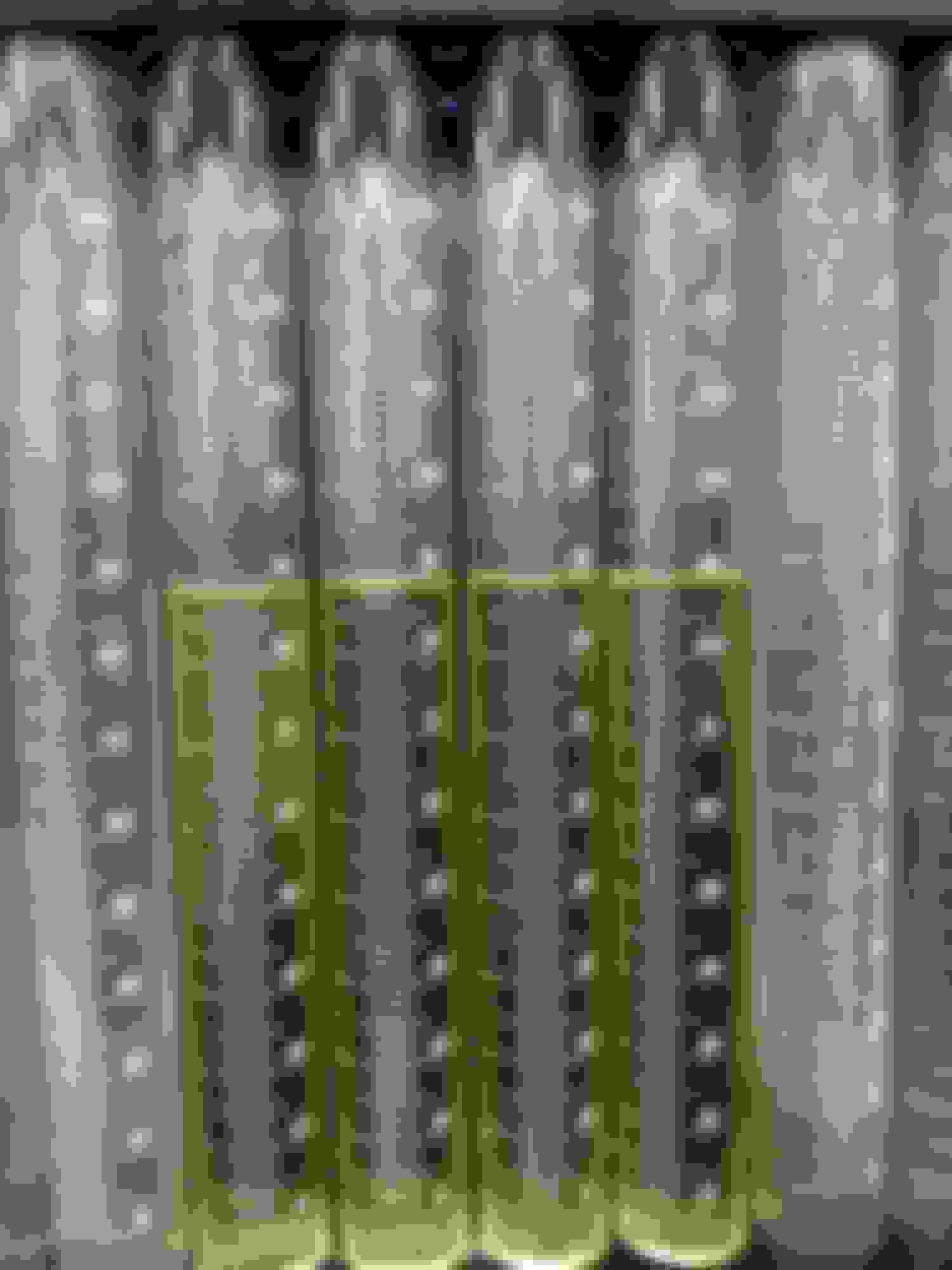
I flowed my injectors today out of curiosity. They are painted black, which im guessing means theyve been serviced in the past. First go of it there was certainly an outlier. I changed the baskets and sonic cleaned them for a few min and then they were much more consistent. The flow measured pretty close to advertised. I'm impressed.
Test Press [psi]: 60
Inj Time [ms]: 6
Inj Count: 1245
volume [cc] Flow [cc/min] flow @2.5 bar [cc/min]
#1 88.0 706.8 549.4
#2 88.0 706.8 549.4
#3 88.5 710.8 552.5
#4 89.0 714.9 555.6
Sorry for the poor formatting....
Spray patterns look OK. Kind of sloppy compared to a nice modern injector tho.
A couple more pictures of fittings that i missed in the post the other day.
I found the thermostat and housing interesting. The relief valve under it is sort f unusual.
no external bypass hose with this thermostat design! in the R100 SAE paper, 700079, Mazda tests different thermostat bypass designs, the graph is water temp vs time @wot. you get the distinct impression that they used a car on a track vs a dyno, but 1970 was early days for them
the winning design, which had best temp control, is the one they have kept since.
there are other cars that use a similar design, off the top my 1958 Tr3 did. it seems better than say an E30, which uses something else, and then needs 7 radiator hoses, which is just stupid. (its actually more like they designed the engine, and forgot to put a cooling system on it, so they just kluged some junk on as an afterthought, which is how the rest of the car is. oh we need a relay? we'll just add it in, and screw it to the fender next to the relay box)
Phil, what's up man! It's Michan from the Zips team. I forgot you had an FC too. It looks like you should have a pretty sweet build on your hands. My project has been abandoned for probably 5 years now... I've just been so busy with life I haven't gotten around to finishing it up.
I sure miss them FSAE days and raising hell in Europe though!
Yea it seems pretty elegant. I'll have to look up that SAE paper, it sounds interesting.
Micham,
How's it going? Nice, yea i've been stalling on mine for a couple years trying to save up the money for it. Finally making some progress on it now. Ha ha true that, i'll be traveling with the WEC cars next year so i'll get some more euro trips, but i doubt they'll live up to FSG....
I made some progress this week stringing wires. I got a variety of heat shrink, and some boots to use at breakouts this week. I still need to get boots for the connectors, and will need to get some more wire, i used up almost everything that i have which was a pretty rough guess. At least i have a better idea of how much and of which colors i need more.
I took the FEM01 and 02, BAC, wiper, and cruise connectors from a donor harness. I also took the firewall grommet. I am not sure yet if i'll use the BAC connector, i may cut the offset key off the BAC so i can use a new connector that has a centered keyway.
First wire strung... Its been a long time coming...
Starting to look like progress
Printed shrink tube labels are great.
Firewall grommet, FEM-01 and 02, BAC, Wiper, and cruise control connectors that i robbed from a donor harness.
variety of DR-25 and Raychem boots, this stuff is expensive...
i also live in Mooresville. I think i may have seen your car like two years ago I only seen one black turbo2 model since living here. I have a sunrise red s4 with s5 tails lowered with 10 spoke white wheels. its been down for a few months now though. Ive have been saving up to turbo it.
I like your attention to detail. I'll be creating a new harness when I install an MS3X in my car so I will compare to how you have done your harness to be sure that mine can be decent. Looking forward to updates!
I ran out of wire again last weekend, apparently i cant count.... I'll get more this week and try to finish laying the wire and then start twisting. I'm starting to sweat that step, I'm afraid that its going to be a huge headache.
I did get all the splices done, so things like power and grounds that are common to several connectors are all spliced together. Now hopefully they end up in OK places when it comes time to twist it all.
I also got my order of sockets for the FEM-0x connectors. I'm excited that i was able to get those, now i can do a legit job of interfacing to the FEM connectors. Unfortunately i will still have to cut and splice the wires going to the front harness that i need. Also, i had to order 1000 of them so i have a few spares if anyone is interested...
Great build and great choice on the ECU! We're having a Black Friday sale coming up soon FYI...
Actually, if you don't want to spend money on ID's we've got some slightly used but cleaned RX8 injectors. They're miles better than those old Denso's and somewhere we may have the injector data.