When you click on links to various merchants on this site and make a purchase, this can result in this site earning a commission. Affiliate programs and affiliations include, but are not limited to, the eBay Partner Network.
I'm in the planning stages of a big project on my 1988 FC TII. My plan is to run it on a MoTeC M150 and I want to document it somehow. I think this is as good a place as any to do so.
First off, let me tell you a little about my background to give this some credibility. This isn't going to be what I think of as a typical forum build...
I have a degree in Mechanical Engineering from RIT where i got my first experience in motorsports. I was part of the Formula SAE team there and spent far far far more time working on the racecar than i ever did on school work. I was there from 2010 to 2013 meaning cars F19 thru F21. I was the lead powertrain engineer for F20 and F21 (F21 was the most interesting with a full carbon monocoque, big wings, and a turbocharged motocross engine run on an M400, weighed 320 lb, and could corner at 2.5G. it was sweet, but broke a lot...). I started working for Roush Yates Racing Engines last summer (after the last FSAE comp) doing EFI tuning and track support for the NASCAR program (RYE does all the Ford NASCAR engines, DP engines, Boss Mustang race engines, and few one off projects...). Last Fall i moved over to the Daytona Prototype program to work on development, design, EFI calibration, and track support. Thats a much more challenging program endurance racing a 600HP twin turbo 3.5L V6 based off the production EcoBoost in the Taurus and F150. Needless to say I know how real racecars are designed, built, tuned, etc. I also, almost always feel like i can do whatever anyone else has done, only better, given enough time with the right tools.
In short, this project is a way for me to play on my own time with some of the stuff i want to try but havent gotten to on the real racecars. Also, i want more boost and rotary engines sound cool... Anyway, i have a black 1988 RX-7 TII that is almost stock and is in really nice condition. The only things not stock are a crappy cone filter, a crappy security system, a nice cat-back racing beat exhaust (which has, unfortunately, rusted out near the muffler so that it is now crappy. It was a NY car but doesnt have rust anywhere else), a crappy DVD player and some crappy speakers. I plan to get rid of those soon. The interior is nice and the paint is pretty great for a 25 yr old car. My plan is to piggyback a MoTeC M150 on the stock ECU to log some data and get something to make a base map from. I also want to understand how some of the cold/hot start stuff works (that is often the most time consuming stuff to tune and i want this to work better than stock without compromising on drivability). I then want to make a new wiring harness and modify the intake to include a good manifold air pressure sensor and get rid of most of the emissions crap and then swap over to the MoTeC completely and get it calibrated well. Eventually, meaning probably when i blow it up and hopefully when i have more money, i will do a little more involved build including a better turbo etc, etc.
Im sharing this online for a few reasons. First off, i want to brag a little as i expect most people on here do, but more importantly i am interested in some feedback and especially in interest from other people who want help doing similar things. The big problem with this project is that ive grown accustomed to big race team budgets and I dont have that here. Nice parts and development cost a lot of money so i am looking for opportunities to make some of my money back. Im not trying to profit off this but i am trying to fund it at least partially so that i can keep going with it. So, if you are interested in any of the work i do along the way, like for instance if you want a wiring diagram or maybe an entire harness, let me know and we will see if we can work something out. Im also probably going to design some parts that will be expensive to have made unless i can get a group of people interested to where we could get a batch made with a much lower per part cost.
Thanks for reading and please do give me some feedback. I'm more interested in a conversation here than a monologue. I'll post back shortly with my progress so far...
I think that i am pretty well set on the MoTeC M150 ECU. Its part of their new series of ecu's that is a big step up from the old hundred series. Its a VE/flow based fueling model and, most importantly, with the Build licensing you can work on the code to add your own functionality and modify strategy. That is the part i am most interested in. I work with the Bosch Motorsports ECU's quite a lot which are great but it costs a fortune to have Bosch make any sort of strategy changes.
The M150 is the high pin count port injection plastic connector version of the M1 series. ( I thought about trying to direct inject this thing someday in the future but haven't had much luck finding a hi pressure pump that could be integrated reasonably easily so ill stick to port for now...) I was hoping to use the smaller M130 but i want more IO than it has and its more affordable to get a 150 than it is to add a VIMS to the 130.
The problem with an M150 is cost. Its pretty expensive as you might expect, particularly once youve added on the advanced logging and Build licensing.
I will make a new engine harness and replace many of the sensors. I plan to eliminate the MAF sensor and do speed/density fueling. I will need a better manifold pressure sensor and air temp sensor for that. I will also eliminate most of the emissions stuff. I hope to use the existing crank angle sensor for now. I want to add a pre-intercooler temp and pressure sensors. I will of course replace the narrow band O2 sensor with a wideband. Id like to add a EGT sensor too, if i can find one that will live...
I havent come up with a good solution for the throttle position sensor yet. The factory sensor only gives data at lower throttle angles. That should be enough for most functions but i would really like to have complete data. One idea is to mount a string pot somewhere or i might just switch to an electronic throttle. That's tempting since you can do some fun things with throttle control but i hate the feeling of disconnect that's common in OEM drive by wire cars. I think thats mostly because of the OEM calibration so i think i could avoid that with a better tune, however there will always be some delay. Im not sure if the roughly 30 msec delay is noticeable or not. Id hate to do all the work to integrate ETC and then not like how it feels...
I want to eventually add wheel speed sensors, accel, yaw, and maybe suspension travel. That will be a later project however...
Mechanically i dont plan to change much more than is necessary initially (mostly because of cost). I will eliminate most of the emissions equipment and might switch the throttle. I will need to invent a better turbo inlet too once the MAF is removed. I will need to modify the intake manifold to integrate a MAP sensor, remove the emissions stuff, and might look at doing some porting while im working on it. I hope to keep the top mount IC for now but will look into moving it eventually. Itd be pretty sweet to turn the hood scoop into an intake and mount the IC up front. Has anyone done before?
I want to convert it to E-85 or flex fuel eventually but that will require upgrading the entire fuel system and wont have any benefit until i start turning up the boost so ill stick with premium for now.
Ive been accumulating sensors for a little while now. I have a few good sensors but still need some more.
I have 4 Kulite amplified pressure transducers. They are 0-100 or 0-150 psig range and pretty accurate. They are pretty old and untested but my experience with Kulite in the past has been great. Kulite was able to provide me with the cal sheets for 2 of the newer sensors so i have a good place to start on calibrating them. I will use them for oil pressure, fuel pressure, etc. I might use one for a boost pipe pressure too but the range is a little big for that. I might also use one for an exhaust manifold pressure, although i have broken really nice Kulite sensors doing that before. Once in a while the pressure pulse from a bad knock will make it into the exhaust manifold and the sensor cant handle it.
I also have a 3 bar Bosch MAP/AT. Ive used these in the past with pretty good luck (as long as you dont get them wet). Also, i have a lot of Bosch Motorsports documentation on similar sensors from back when they sponsored my FSAE team. I hope to be able to mount it in the intake manifold without too much trouble.
I still need to get some temp sensors. I want a good oil temp, water temp, pre-IC, and EGT. We run a pretty trick KA air temp sensor on some of the race motors at RYE so id like one of them but they are pretty expensive. The EGT is tough too. I just pulled a turbo off the dyno at work this week that had a lot of damage to the turbine wheel from the tip of a thermocouple that couldnt handle the heat. Anyone have any good suggestions on a tough EGT sensor?
I plan to make a full motorsports grade wiring harness for the engine. Since its ridiculously expensive to do that ive been trying to have a good plan before i start working on it. I have bought 2/accidentally won 2 ebay auctions on factory engine harnesses to use as a pattern. I will lay it out on a pin board to get lengths, junctions, splices, etc. And then when im done ill try to sell them. I have a turbo and a non turbo. let me know if youre interested.
Currently i am working on a schematic using TinyCad http://sourceforge.net/projects/tinycad/ which is an opensource schematic software. Its pretty powerful but takes some set-up to get it up to speed. Its mostly intended for a lower level electrical schematics so i have been working on a library of parts that make more sense in a motorsports wiring harness application.
The biggest challenge with the harness is choosing which connectors to use. Id love to use AutoSport connectors, but i dont think i can afford those. Ive used both Deutsch DTM and IMC connectors in the past too and they are much more affordable. The IMC's are really small and package nicely but are not as robust and once they get a little dirty they get very tough to connect and disconnect. The DTM's on the other hand are huge and silly looking but are bulletproof and super easy to work with. Most of the Amphenol connectors are heavier and still quite expensive. Fischer and Odu and Limo all make some awesome connectors but again theyre way out of my price range. I have not come across any other affordable alternatives. Im looking for any feedback you have here.
DTM
IMC
AS
ODU
Fischer
Limo
Also, i just bought a label maker to print labels on shrink tube. Dymo Rino 4200 its pretty affordable but the shrink tube cartridges are a little more expensive. Its well worth it in the long run tho. You end up with a much more legit parts.
Well, wherever your build goes, you are certainly thorough. Good luck with the project. I'm an FSAE alum too. I spent a couple of years working on formula cars at USF while I was an ME major before I switched to geology.
Nice. I am going through the same process with my car and wiring. I was looking at AS too, but I agree too expensive for my purposes/budget. I will be going with DTM connectors. I had a few hiccups recently but I'm trying to save for the tefzel wires and raychem heat shrink needed. Never thought I would say I'm saving up for wires and heat shrink, but damn that stuff is expensive!
FAL,
Nice, yea im starting to lean toward the IMC's because they package so much nicer and look a lot nicer. There are some cheaper brands of heat shrink that are still really good. I'll try to look up the one i used in the past. The important thing is getting adhesive lined. Same with the wire, there are some affordable sources of teflon insulated wire. I havent looked at that too closely yet but will post when i do.
Ive been working on my wiring diagram and have mostly figured out how i will integrate my new harness with the existing car wiring. I will replace the Emissions harness completely and move a few things from other harnesses to it. I will add the crank angle sensor to this (instead of thru the front harness) and will add connectors for doing individual coils (although i will stick with the existing coils wired thru the front harness for now). There is one existing connector from the front harness into the ECU which i will have to pick up some pins from. There are also 2 connectors on the EM harness that tie into the F harness that i will have to keep at least partially. I still havent decided what to do with the wiper motor wiring. It goes thru the EM harness now but i would really love for that sort of thing to not be in my harness. If there's an elegant way to make it separate i might do that but im afraid its only going to work out well to include it in my new harness.
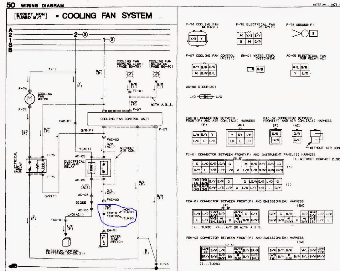
One thing that stuck out to me in the wiring diagrams i have for the car is for the water temp switch for the fan control. i think the diagram has a typo and they have the turbo and non-turbo connector numbers swapped.
Is anyone familiar with this? (i tried to check in my ebay harness and realize that it is in fact not a turbo harness. Perfect. I paid extra for it because it was supposed to be...)
Also, does anyone know what sort of logic the fan control unit has? If i can control it predictably by tricking it with that water temp switch signal i will keep it as is and tie it to an output from my ECU but otherwise i will need to bypass it and control the fan directly.
. Id like to add a EGT sensor too, if i can find one that will live....
EGT stock isn't actually that high, a stock ECU car will be under 750c peak. they have to keep the cat alive, after all.
Originally Posted by Audiophile426
I still havent decided what to do with the wiper motor wiring. It goes thru the EM harness now but i would really love for that sort of thing to not be in my harness. If there's an elegant way to make it separate i might do that but im afraid its only going to work out well to include it in my new harness.
its actually really easy to depin the stock wiper wiring, and just transfer it right over to your new harness. i do agree its not as simple/ideal as it could be, but in the scheme of things its like 5 extra minutes to add the wires.
One thing that stuck out to me in the wiring diagrams i have for the car is for the water temp switch for the fan control. i think the diagram has a typo and they have the turbo and non-turbo connector numbers swapped.
Also, does anyone know what sort of logic the fan control unit has? If i can control it predictably by tricking it with that water temp switch signal i will keep it as is and tie it to an output from my ECU but otherwise i will need to bypass it and control the fan directly.
Thanks for the feedback,
the S4 has a couple of differences like this, so i'd suspect the diagram is correct.
that fan system is weird, it looks like the ECU can't switch the fan on until the fan switch is on? it is only an aux fan too, so it shouldn't run much.
j9fd3s,
Thanks for the feedback. Good point on stock being reasonably cool but i plan to ditch the cat before long and start pushing the temps a little harder. Most of the ones i've broken were 1/8" im sure a 3/16" would last a lot better.
Yea im not worried about the wiring part of it i'd just rather not have a noisy power transmission line run thru my harness near all my sensors. I will try to shield stuff so that it shouldnt be an issue but i still dont like the idea.
The diagram i am looking at is supposed to be for an s4 but it doesnt make sense. The G/B wire in FEM-02 is replaced in the Turbo harness and there is a G/B wire added to FEM-01 in the turbo harness (aside from the G/B in FEM-01 in both harnesses that is for the cruise control). This would make sense if you assume they made a typo. I was just curious if anyone has verified this?
I still havent figured out the fan exactly. Best i can figure the ECU doesnt have any control over the fan its just the water temp switch and the refrigerant pressure switch. Im not sure of the logic tho. It kills me that all the sol. and relays are shown normally closed when im sure not all of them are.
Is anyone familiar with making the idle control work with a stand alone ECU? My question is if i can eliminate the air supply valve and the air bypass valve? My understanding is that the air bypass is only used for hi-idle on a cold start (ok that can go, no issue) and the air supply valve is opened when the power steering is loaded or the A/C is turned on. I get that originally this was because the 80's electrons weren't smart enough to handle the quickly changing load so this extra bypass was sort of a crude pre-control to help minimize the change that the feedback controlled BAC valve has to make. I dont think i would have any issue accomplishing the same thing with just the BAC valve as long as it can support enough flow for the extra load of A/C, etc. So does anyone know what sort of duty cycle the BAC runs at typically? And how big the air supply valve is in relation?
I found some neat looking new connectors tonight. They are Deutsch 369 series and seem pretty legit. I looked up pricing and they are a lot more expensive than DTMs (~$10 instead of ~$3 a piece) but way cheaper than AS or the like. They are much smaller than DTMs, although still larger than IMC, and use the smaller size 22 pins like IMC and AS. These are pretty trick too in that they have different keys (like AS) and as i understand it you can put pins or sockets in either the plugs or receptacles. That makes it much easier to key things such that they cant be plugged in wrong but still keep the sockets on the powered side of all the connectors (ive seen more than one ECU get nuked by having pins on the powered side of the connector)
I had been leaning toward the IMC connectors since they are so much smaller (and work with a boot better) than the DTM connectors but now im really interested in these. Ill try to get a couple samples to play with before committing since they are much more expensive.
The BAC can be ran like any conventional 2-wire PWM idle valve. It can be used as a cold start high idle, dashpot, high idle under input load, ect. Seach around the Megasquirt subforum here. Many people reuse the stock BAC with MS.
So 6 months of real race cars happened, and now i'm finally getting back on this. We did win the 24Hr along the way so it wasn't all bad...
JerryLH3, Nice, that was before my time. Do you still follow it? I'm headed to the FSAE comp next week to do some recruiting. I'm hoping the RIT guys do well. Also, does anyone know a really good calibration guy?
I've got a much more complete wiring diagram done now so i plan to order connectors, wire, shrink tube, and boots soon. Does anyone know an affordable online source? I'll probably ask MoTeC for a quote, hoping that they'll give me a deal if i buy an ecu from them too.
I still havent decided on which connectors to use (where i have a choice). I still cant afford ASL's. Any new suggestions?
I will start a peg-board soon to start laying out the harness, i have a couple of used harnesses i can use for a pattern.
I got really interested in the new Bosch MS6 series ECUs since they are competitively priced and i am far more familiar with that stuff. We run MS5s on the DP cars. Unfortunately they dont have any rotary software for it so it'd be a bit of a hassle to trick it into running a rotary. I tried to talk our software guy into writing some code to do it but didnt have any luck and i certainly cant afford to pay him to do it. So now im back to looking at the M150 MoTeC.
I still have a few details to work out before i really commit to this project. I need to decide what coils to run, id like to ditch the factory coils if i can afford something nice. I want a coil near plug style, and preferably one that has the igniter built in. I know the LSx coils are popular, are they a 3 wire style? Does anyone have a good suggestion for an alternative?
I also need to work out how to install my MAP sensor as well. I'd like to find another manifold that is affordable so that i can modify it and mount my new sensor prior to tearing my car apart.
I also want a better TPS sensor. Has anyone seen an elegant solution? I've toyed with doing an electric throttle but i think that i want to make it work on the factory throttle first. I'll protect for that upgrade in my harness however.
The next few weeks will be pretty busy with real race cars but i hope to get some more free time before long...
I still have a few details to work out before i really commit to this project. I need to decide what coils to run, id like to ditch the factory coils if i can afford something nice. I want a coil near plug style, and preferably one that has the igniter built in. I know the LSx coils are popular, are they a 3 wire style? Does anyone have a good suggestion for an alternative?
j9fd3s,
Thanks for the link. There's a lot of good info there. I've always come from an engine architecture that had plenty of time to dwell so i hadn't put much thought into that short of a cycle time. I'll do a little more math before choosing a coil...
Yea the Ganassi car is my primary deal. It was a really disappointing race. We had a good car but had an odd gearbox failure just after Joey got in. He was just cruising staying out of the way (/ waiting for the second Mazda to break) and was still setting good laptimes. So it goes...
So it was only 3 months this time.... This new Ford GT racecar is a lot of work....
Anyway, I've made a little progress on this project. I started a pin board to layout my new harness. I have 2 used harnesses (unfortunately neither are turbo parts) that i am using for a pattern. I'll also steal some parts off one for some of the connectors i'll need to re-use, like the emissions to front harness connector and the wiper and cruise connectors. Neither are in good shape, but i might fix up whichever one i don't pillage if anyone is interested in a non turbo emissions harness.
Pin board
I've also bought a sample TE 369 series connector and really like it. I just ordered the rest of the connectors i will need. It was about $450 worth, which is a lot more than if i used DTM's but the 369s are much nicer. Not nearly as expensive as if i had gone with ASL's tho. I do still need buy wire, shrink tube, transitions, and boots, so there's lots more to spend. I got the connectors from Mouser, and found military surplus pins and sockets on ebay. I would definitely recommend hunting for pins, i think i got about $200 worth of pins and sockets for about $40.
I am almost finished with my wiring diagram, although im sure i will have to revise it as i layout the harness. I am also hoping to get a Bosch MS6 ECU instead of the motec. The only problem with the MS6 is that it doesn't have a crank reference mode for a 2 stroke style firing once per rev. I would need to make an odd trigger wheel to trick it into firing once per rev. I have been working on the Bosch guys that do our software for the racecars and he tells me that the FPGA needs to be programmed in Europe. I guess they are working on updates to the FPGA but he didn't know if they will do a 2 stroke mode. Fingers crossed. If they dont do a 2 stroke mode, then i will stick with the motec.
I've been falling behind on updating this thread with my progress.
I finally bought an m150 with the development license and level 3 logging. I also bought a single channel LTC from motec. Now that i have some really expensive electronics, i have a lot more ambition to work on the harness.
I think i have been claiming that my wiring diagram has been completed for about 2 months, but every time i look at it i make some more revisions.
The actual harness layout is another story, i have a couple of NA harnesses that i was going to use for a pattern but i've come to realize that they are more different than expected. I have a start of a layout but need to do some more disassembly on my car to get some more measurements.
As far as sensors, i have a set of 4 Kulite pressure sensors that i'll use for ambient, water, fuel, and oil pressure. I bought -4an fittings to fit where the existing oil pressure sensor is mounted as well as one for the 1 wire water temp sensor in the top of the thermostat housing and one to replace the fuel pulse damper banjo on the fuel rail. I got a new bosch water temp sensor, although the stock one will probably work fine, im just not sure of the calibration. I also found an m14 version of the bosch ntc temp sensor from a BMW/saab/volvo application that should fit in the oil pan where the sub zero starting switch normally fits. I got a new pig tailed bosch knock sensor, but I think the factory knock sensor is an m10x1.25 thread, the bosch sensor uses an m8 bolt. I think that an m10x1.25 is just a tick larger diameter than an m8x1.25 helicoil, so i will attempt to helicoil the stock location to m8x1.25 for the new sensor. I have a bosch MAP/AT sensor that i think i can mount on the front face of the square section of the upper intake manifold. Its a little tight with the OMP linkage. I am not sure how well that location will work for measuring intake air temp so i would like to replace the factory IAT sensor. I have asked KA sensors for a quote on an m10 NTC2 sensor but havent heard back from them yet. I would like to add another MAP/AT sensor in the boost pipe, but haven't figured out where to mount it yet. I will also add a flex fuel sensor eventually, but this thing will need new fuel lines, pump, injectors, etc before it will be happy with e85. I would also like to add a boost **** on the dash but havent found a sensor i like yet. I will see what the Ganassi guys use in the DP car this weekend and maybe get one of those. Although i think they make a trick billet **** for the switch that i probably cant afford.
Feel free to ask questions, im not really sure what details are of interest.
Be careful when adapting the coolant and oil to -4AN. The 1988 model came with 1/8" BSPT for oil pressure and EITHER 1/8" BSPT OR 10mm x ?? threads for the coolant temp sensor (by the oil sender). A 1/8" NPT adapter will easily START in either of those holes, but will crossthread after a few turns.
For the OEM coolant temp sender (in water pump housing), you use these 3-point calibration numbers:
-20�C = 16200 Ohm
20�C = 2450 Ohm
80�C = 320 Ohm
Unless you're reusing the stock top-mount intercooler, don't bother finding an air inlet temp sensor in the correct metric thread. Buy a Greddy inlet for a front-mount and tap the sensor location to the appropriate NPT.
You don't see many people building motorsports-quality harnesses for these cars. Good luck and make sure to post pictures.
Shainiac,
Thanks for the info.
I got a bspt to -4 fitting for the oil and i plan to use the water temp switch location (top of the thermostat housing), which i think is an m16 thread. I am keeping virtually all of the stock hardware including the top mount IC for now since i have spent all my money on electronics. I got a quote back from KA and they want ~130 for the sensor. Thats more than i want to spend so I'll keep hunting for something cheaper, and likely tap a new hole in the housing for a smaller, more common thread.
I finally committed to having this thing apart until i am done with this project so i took one last joyride and then started pulling the harness out last night. When i pulled the upper manifold out i found a much nicer spot on the back side of the manifold to mount the MAP sensor. The air bypass value is mounted on a nice machined surface that i think i can modify for my MAP sensor. The one concern is that the small diameter hole into the manifold doesn't appear to be straight thru, does anyone know what that looks like on the inside? i'll pull the throttle body off next time i have a chance to work on it and see.
Im headed to COTA in the morning tho so it'll be another week or so before i get to work on it any more...
When you tap the manifold itself, try to use either the primary runners. The secondary throttle plates are staged and don�t crack until ~10% throttle.
I guess since the runners are still connected to the same rotor as the primaries, they should still see relatively the same vacuum, but I would avoid it. I ended up tapping the rear primary �lump� in the upper intake manifold so I see actual vacuum at low throttles. The stock vacuum nipple for MAP is close to this area as well.
Shaniac,
Thanks for the info. For the MAP location, i want to avoid the runners so i can measure as close to the static pressure as possible. I think either method is OK, itll just change the VE map some. I prefer to pick a really quiet spot in the plenum volume if i dont have to worry about boost scrutineering ha ha. I see you have a fitting in the plenum thats capped off, did you use that location at some point?
Also, tell me about the BAC? it looks like you flipped it 180*, and then removed the coolant block? How did you plug the coolant ports in the block that feed and drain the coolant for the BAC and the throttle body? Id like to eliminate that coolant passage on mine as well, but I havent come up with a great way to plug the ports.