When you click on links to various merchants on this site and make a purchase, this can result in this site earning a commission. Affiliate programs and affiliations include, but are not limited to, the eBay Partner Network.
I'll get more this week and try to finish laying the wire and then start twisting.
Are you concentric twisting the whole thing?
If so, do you factor in the additional length of wire needed? I assume you lose a decent percentage going from laid out straight to twisted up ready for the DR25.
Is there a rule of thumb for how much extra you need?
Great build dude just read the whole thing. Im also in the middle of a mil spec engine harness, well half is complete, i just need to tie in my last breakout and pin out the firewall plug.
Twisting aint to bad with the m22759. You want to work to about a 35 degree angle. I started at 15-20 and it made it heaps harder to twist. Txl/gxl wire is the real pain to twist with. It helps to zip tie the sections as u twist further along. The m22759 stays tight and shouldnt need any ties to hold it.
I noticed your using dr-25 for your splicing shrink. This should really be glue lined for any internal joins but the dr-25 should work ok. I started using dr-25 but did it all again with glue lined.
Im not sure if u have taken this into account but i dont splice untill its twisted so i can make sure my splice is inside a boot.
S2-13BT Allow about 30% extra for concetric twisting.
I have a bunch of drawings and 1000+ photos but these are the only ones i have saved on my phone.
100 things i would do different on my next harness but its all a learning curve. My main thing that i would do differently is twisting. My twisting on the main bundles is really good and is done using proper technique and angle, but some of the break out twising is a bit dodgey. This was done prior to finding out the correct angle to work with and theres not enough angle in the twisting. I was going to redo this again but this was already my 3rd revision and motivation was lacking.
Second thing i would change is the order i made everything. I had pre terminated connectors (autometer temp sensors) and i couldnt buy these plugs or pins anywhere(not even autometer would sell em to me) so i had to start from the connector and work back to the firewall plug, i then spliced these wires to tefzel in the first boot. Seemed like the easiest way to do it at first but the firewall plug is hard to pin out now. Much easier to do it in the reverse order.
3rd thing im going to regret in years to come is my labelling. Should have spent the extra $ to get a heat shrink labelling machine. I just used normal stick on dymo labels. Just looks more professional with the yellow heat shrink labels
I tried to plan 5 years down the track aswell. I have 6 injectors wired up but im only using 4 atm. Electric water pump is wired in but im still running a belt driven water pump.
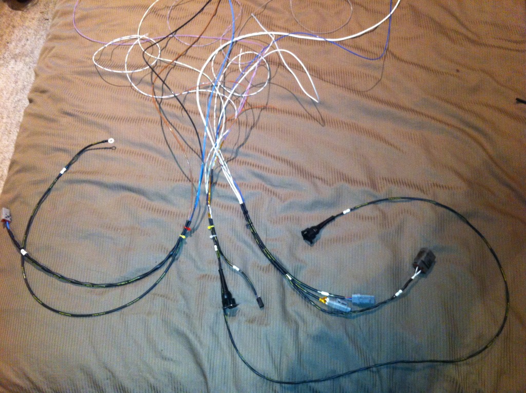
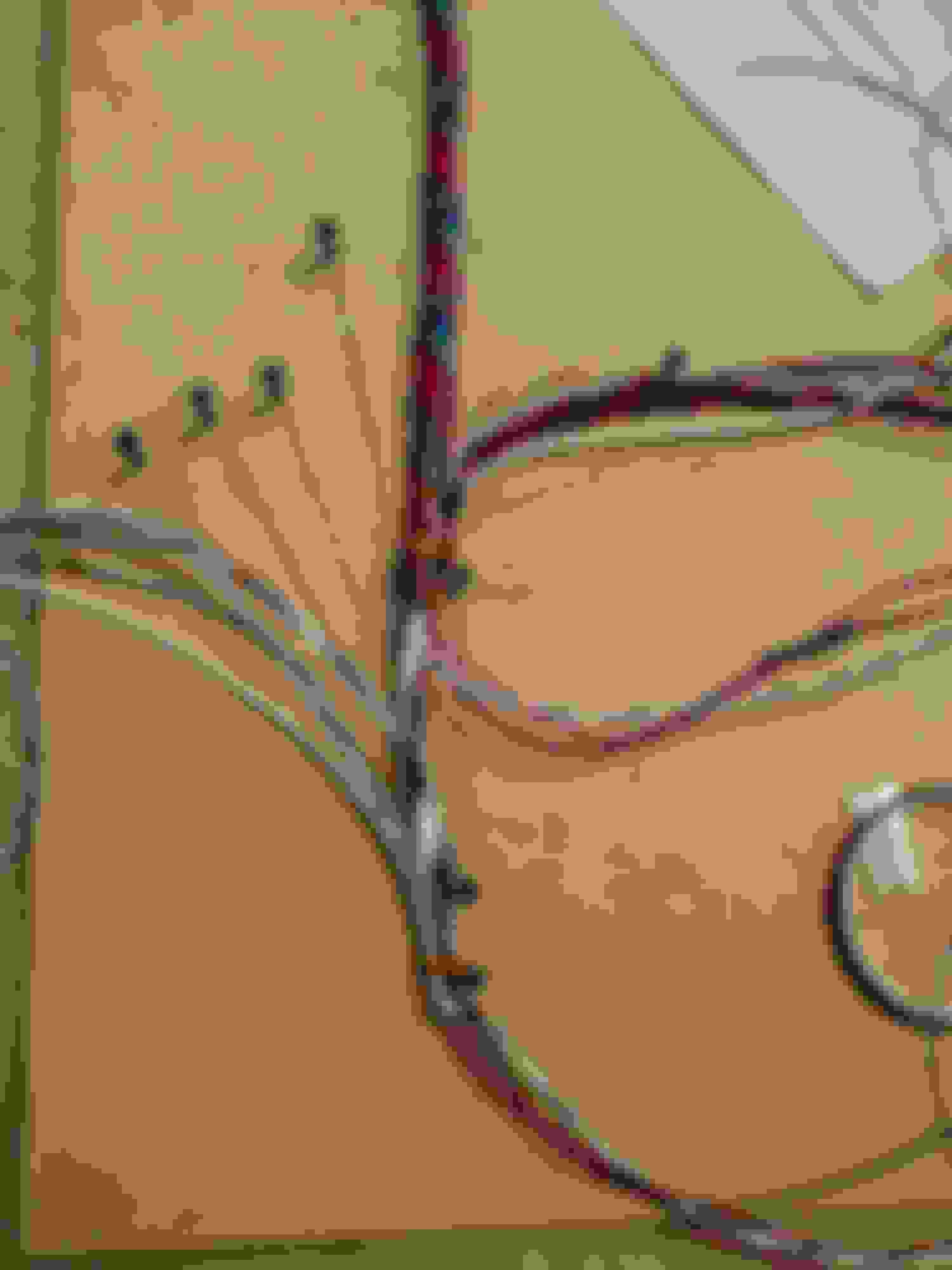
In the photos you can see the first 3 breakouts. One has CAS, TPS and alternator. Middle breakout is 3 water temps sensors (1 guage, 2 ECU, 3 electric water pump controller) last breakout has radiator to block earth (for alloy rad) and electric water pump. I would have preferred to have the electric water pump temp sensor run in the last breakout but i had to make up the thickness in the middle so my boot would shrink tightly.
The next breakout further down the main bundle, has my 6 injectors and then the final breakout has block earths, oil temp and pressure and fuel pressure.
Hopefully my druken ramblings make sense.
FullFunctionEng,
Thanks. Interesting, i'll keep that in mind. Part of my reason for not changing much hardware now is that i want to have some data to show how much different hardware upgrades improve things. So once i get it working and get the electronics sorted out then i'll start upgrading some hardware.
I didnt get much time to work on this this weekend, but i did make some good progress. I got the remaining wires run and cleaned up some of the splices in the ground and power circuits. I learned that the factory ECU only grounds to the engine block, so i've decided to copy that basically, and not tie the ECU to the ground pin in the FEM connector.
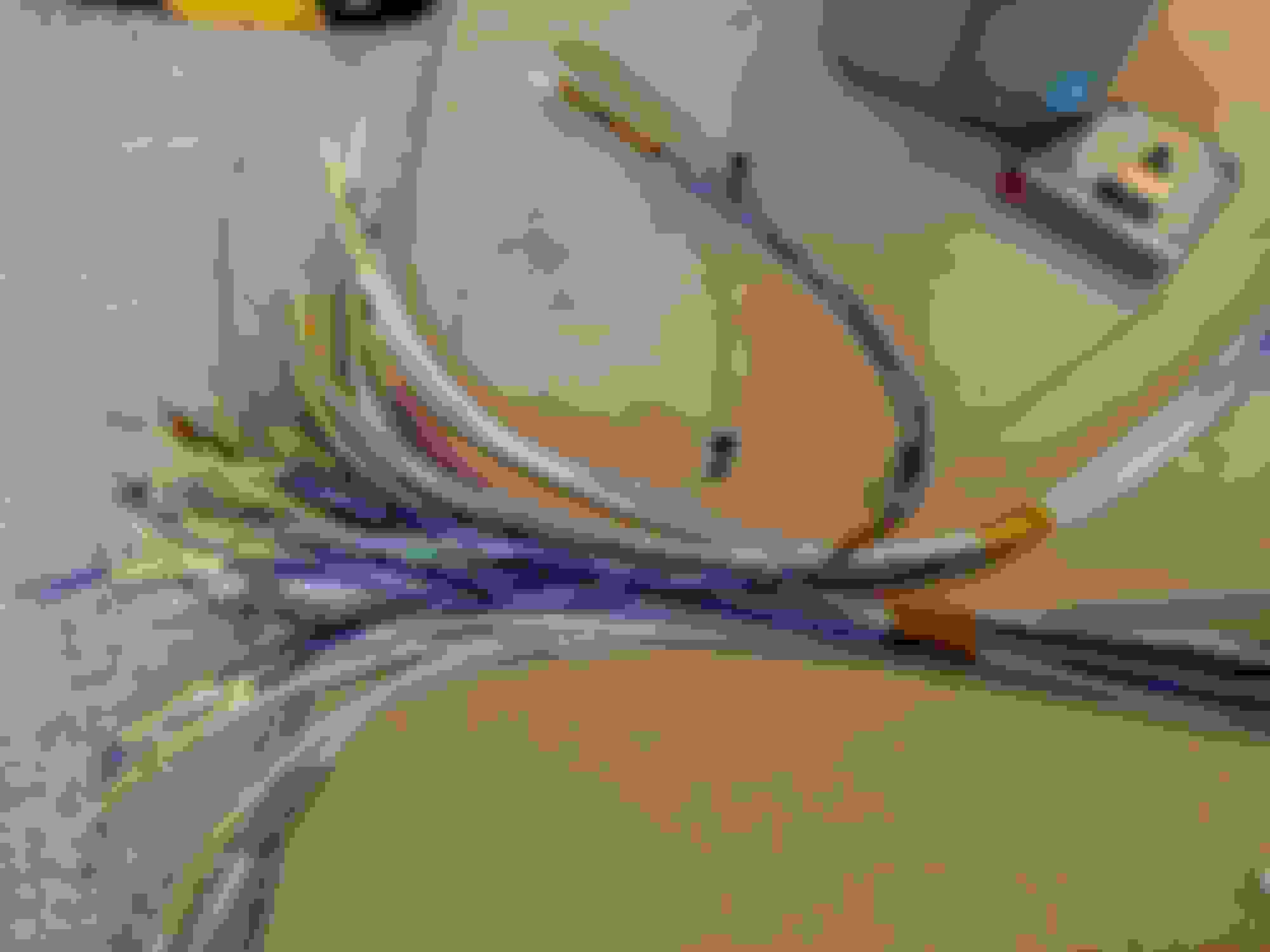
Finished laying out the wires
many labels
My OCD is mildly disappointed that the latest spool of purple wire wasn't the same shade....
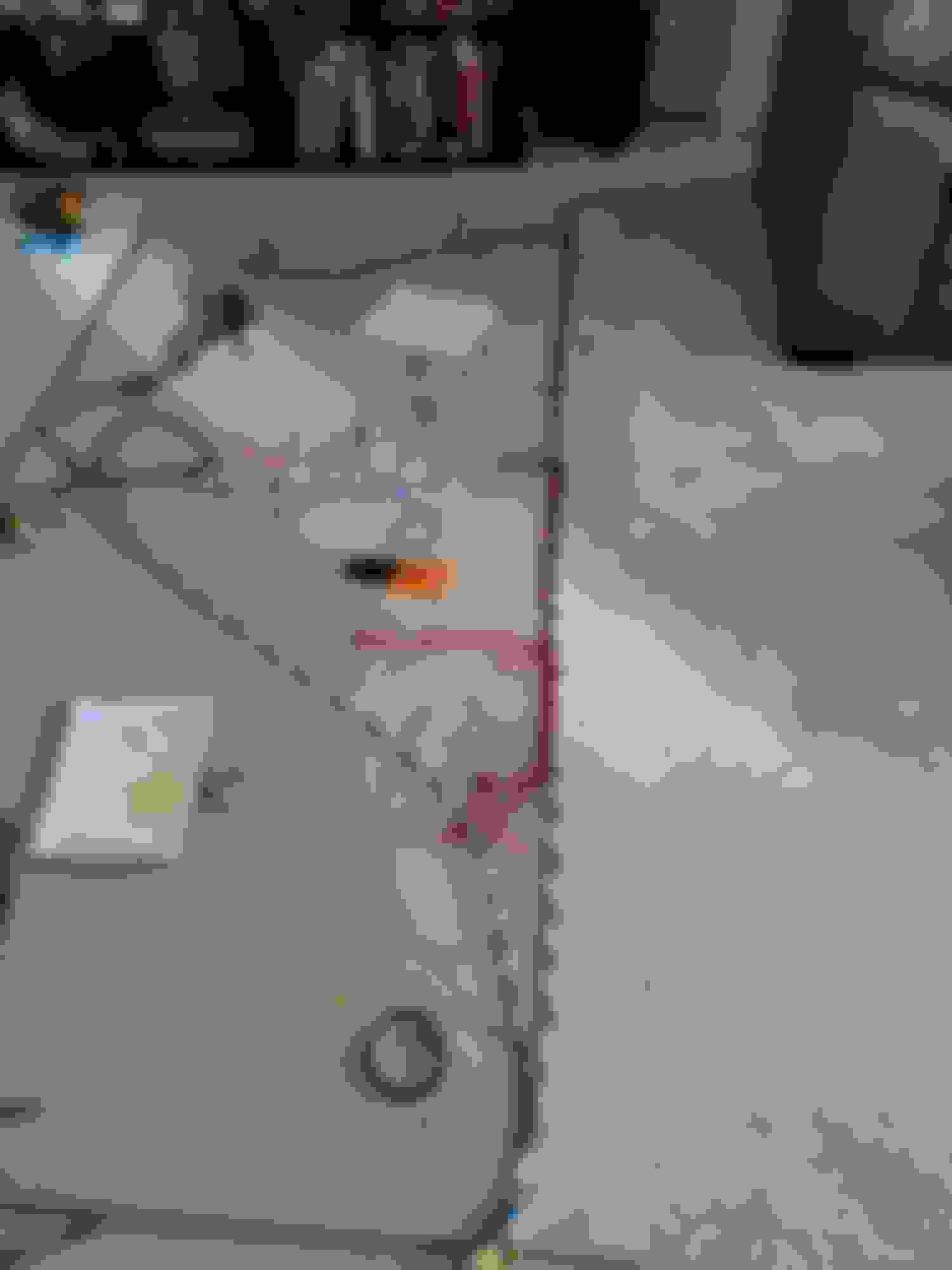
Watch out for this, i accidentally pinched the white wire while crimping this splice. Fortunately i noticed it while it was reasonably easy to replace the wire.
I started twisting wires today and got the branch that goes to the dash complete. So far so good, but that part was certainly the simplest part of the harness. I've got a lot of work ahead of me to keep the rest organized and get it twisted. So far i've learned that i probably should have left the extra wire length at the ECU end and twisted from the connectors back toward the ECU. Now i have the issue of having to comb out the entire harness while twisting from the ECU out. Its not a real issue just a lot tougher to keep things organized.
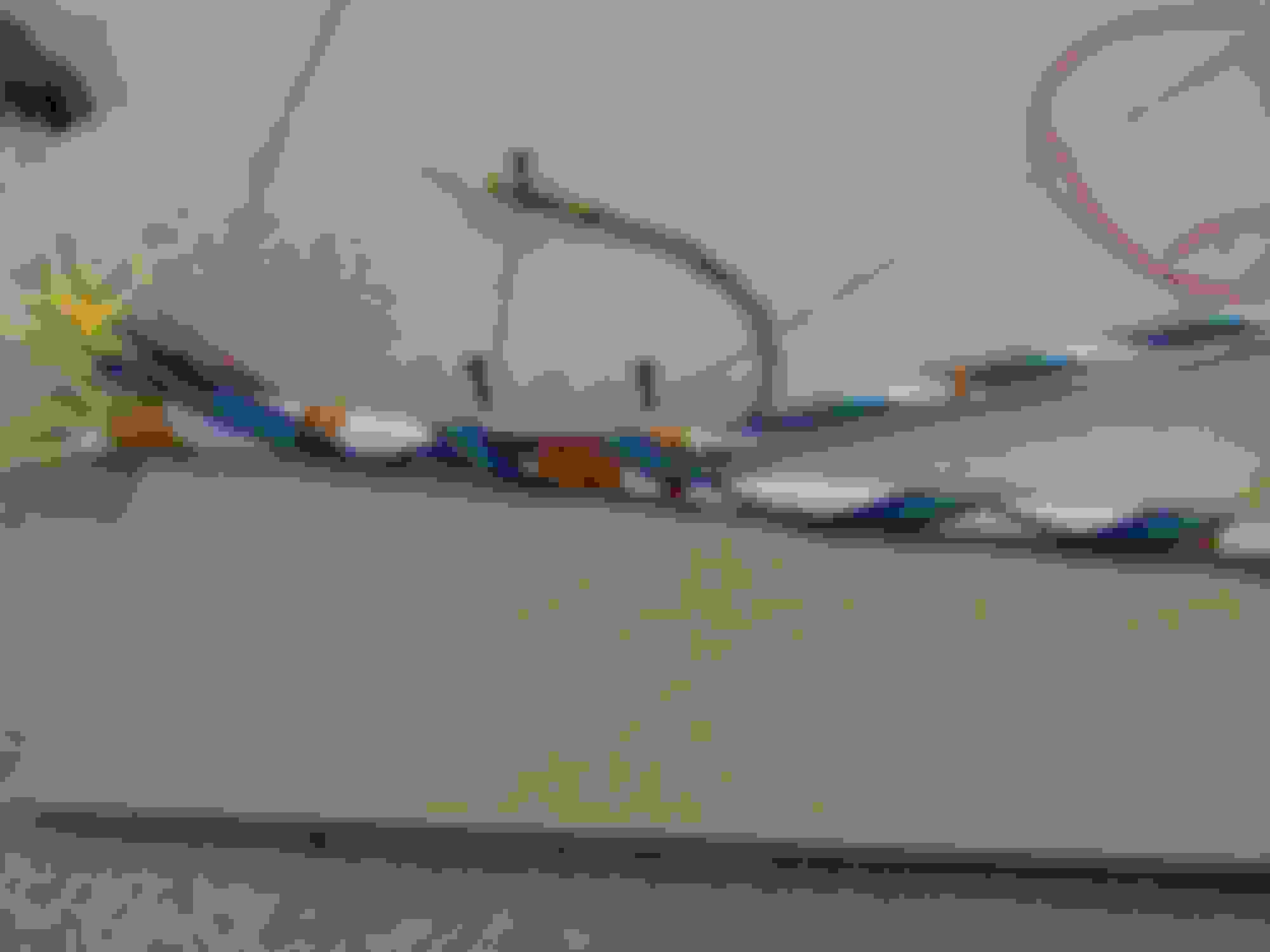
Starting to twist. I've been improvising on the layer counts and not adding filler wires. So far i am happy with the results.
Cambo,
Thanks for the info. Cool to see someone else doing a milspec harness on a 13b.
Whats the concern with using adhesive lined heatshrink on the splices? Just to keep them sealed? Im not as worried about that since the harness itself will be sealed. Is there concern about the heatshrink sliding off the splice in use?
For the breakouts in the harness i will use molded boots and adhesive to make sure that it stays sealed.
I havent measured the twist angles or tried to keep track of turns per inch, but it seemed to lay pretty naturally as i have it so i am reasonably happy with it. Its staying twisted without much help and is pretty flexible.
I certainly fought with the inner layer untwisting while working on the outer layer as i got close to the end. I'll need to be careful of that on the more complex parts of the harness.
So i've got to ask, if your're spending the money on a milspec harness, why use a autometer temp sensor??
For the glue lined shrink, I never understood the reasons 100%, I would say it is to keep them sealed from moisture and to keep it from sliding(more for the 20awg and smaller sizes as the shrink doesnt go tight). This was on the advice of some professional harness builders so i decided to follow their advice. I was in the same boat as you when they told me (its all sealed anyway??)
Autometer temp sensor is just for a temp guage. Dont have a display so still using guages
I havent measured the twist angles or tried to keep track of turns per inch, but it seemed to lay pretty naturally as i have it so i am reasonably happy with it. Its staying twisted without much help and is pretty flexible.
from taking apart a bunch of Mazda harnii, they are twisted, but the twist always seems pretty mild. also there usually are sections that are straighter, and then some that are almost kinked. not really sure why, but it says to me that the twist isn't super critical.
Thanks for the comments guys. It's been a bit since i've had time to work on this. I made some progress this weekend tho. I have most of the main trunk twisted and the break out to the dashboard done. I still have some on the outermost layer of the main trunk to twist and all the breakouts. Its going well for the most part.
I made a couple mistakes that are making it a little less nice, but nothing too bad. One issue was that i didnt choose the layering quite right between the short main trunk and the breakout to the front so that i have to change wrap direction on the layers that go along the main trunk. It actually works out OK but isnt quite right.
Another issue is with the splices along the length. Some worked out and layed in OK, others sort of stick out poorly. Thats mainly a cosmetic issue. Also, i ended up with some lengths that had 1 or 2 too many wires for the layer which made it not twist well. Luckily the layers over it seemed to keep everything tucked in well enough.
Now my biggest fear is that i forgot a wire. God i hope not.
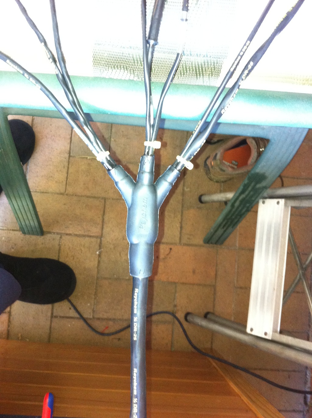
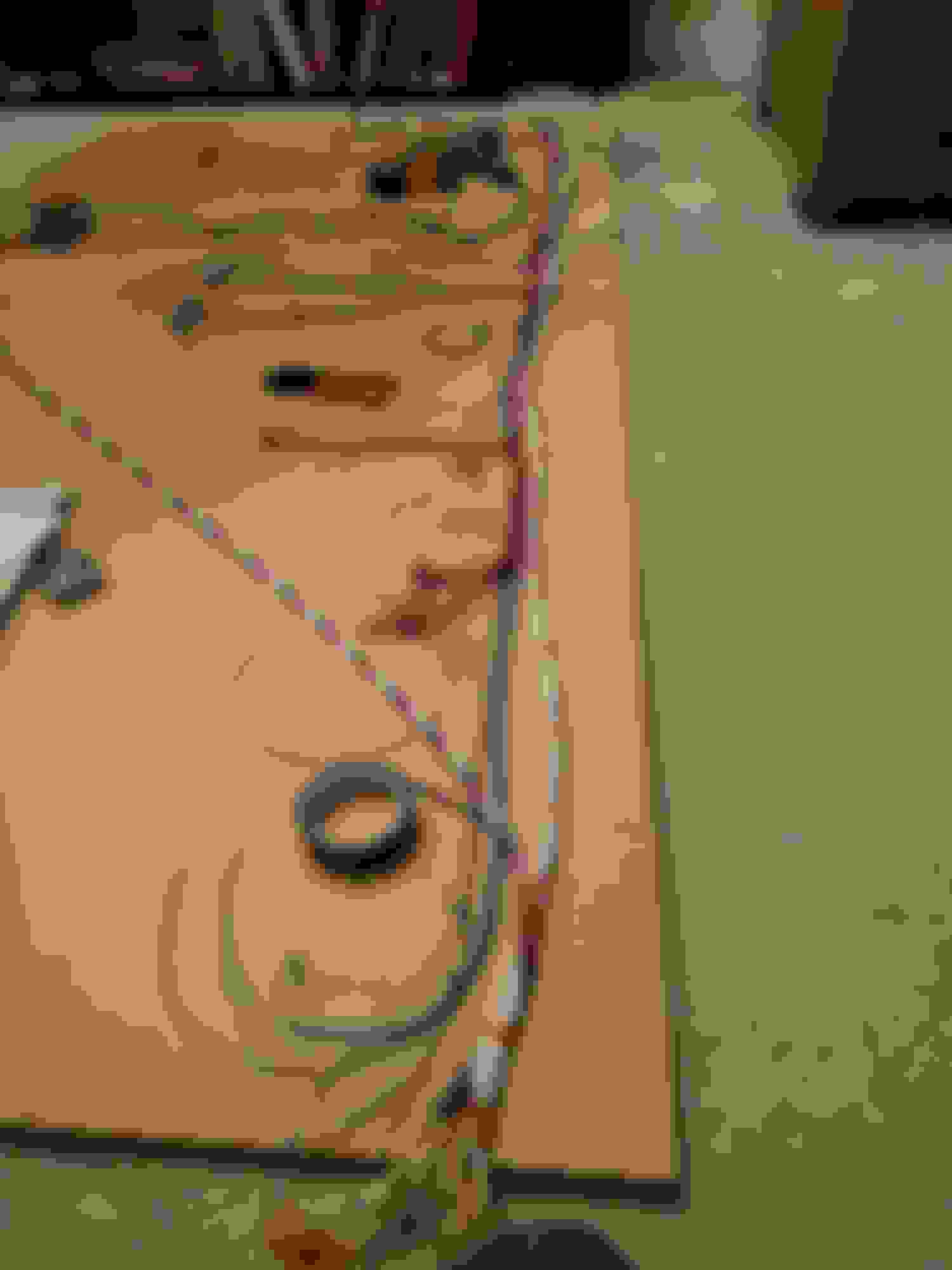
This is the fun part, untangling as you go is a challenge
Notice the change of direction at the first split. Thats a whoops.
You want to use SCL gluelined 3:1 shrink on the splices. DR-25 for splice covering is a no no. dr-25 does not strain relive very well. If the splice does fail the wires will pull out. SCL will help retain the wire. You should also shy away from putting the splices mid run. Typically they are in the molded boots or very close to the ECU/ Firewall connector. Mid run splices make servicing the harness Very Very difficult. Plus mid run splices will flex with the harness and you will put more strain on the splice then is necessary = failures.
You may want to look into lacing cord. It is used to hold layers together/tight. You twist in on top of a layer in the opposite direction. It prevents long lengths from loosening up and between laying additional layers.
Concentric twisting is not hard to twist but it does take a lot of planning to lay out correctly with minimal to no filler wire. I do motorsports wiring for a living. Currently I concentric twist exclusively. I specialize in Rotary with specifics to the FD RX-7 chassis. I do some pretty cool stuff with the FD chassis. I will be glad to answer any questions you guys have on motorsports wiring. Here is a link to my IG account. You can see drawings to a 20b FD standalone engine harness with DBW I completed last week. Plus there are a lot of concentric twists and transitions pictured
Thanks for the tips, the strain relief of glue lined shrink tube makes sense. It's too late for me now, but i will do my best to tape up the splices to help relieve them. I would also make a bigger effort to keep the splices out of the runs, it caused more trouble than it was worth.
I finally finished the concentric twisting. Mostly. I still need to clean up some of the breakouts, etc.
Like EB Turbo mentioned, my splices are my least favorite part at the moment. I wish i had simply run more wires back to the ECU and spliced them there instead. I also came up short on a wire or 2. One of the injector wires ended up about 6 inches short (dont know what i did there, the other 3 were fine) so i had to splice on some more length. A couple other connectors will be an inch or so shorter than what i intended but it should be no trouble.
Next i want to beep out all the wires and make sure i havent made any mistakes. After that i think i can do heat shrink on the straight lengths, i'll leave the boots until the end. Once i have it somewhat protected with heatshrink i want to install it and finalize my lengths. For most connectors i have some extra length over the original plan so there's some room for adjustment.
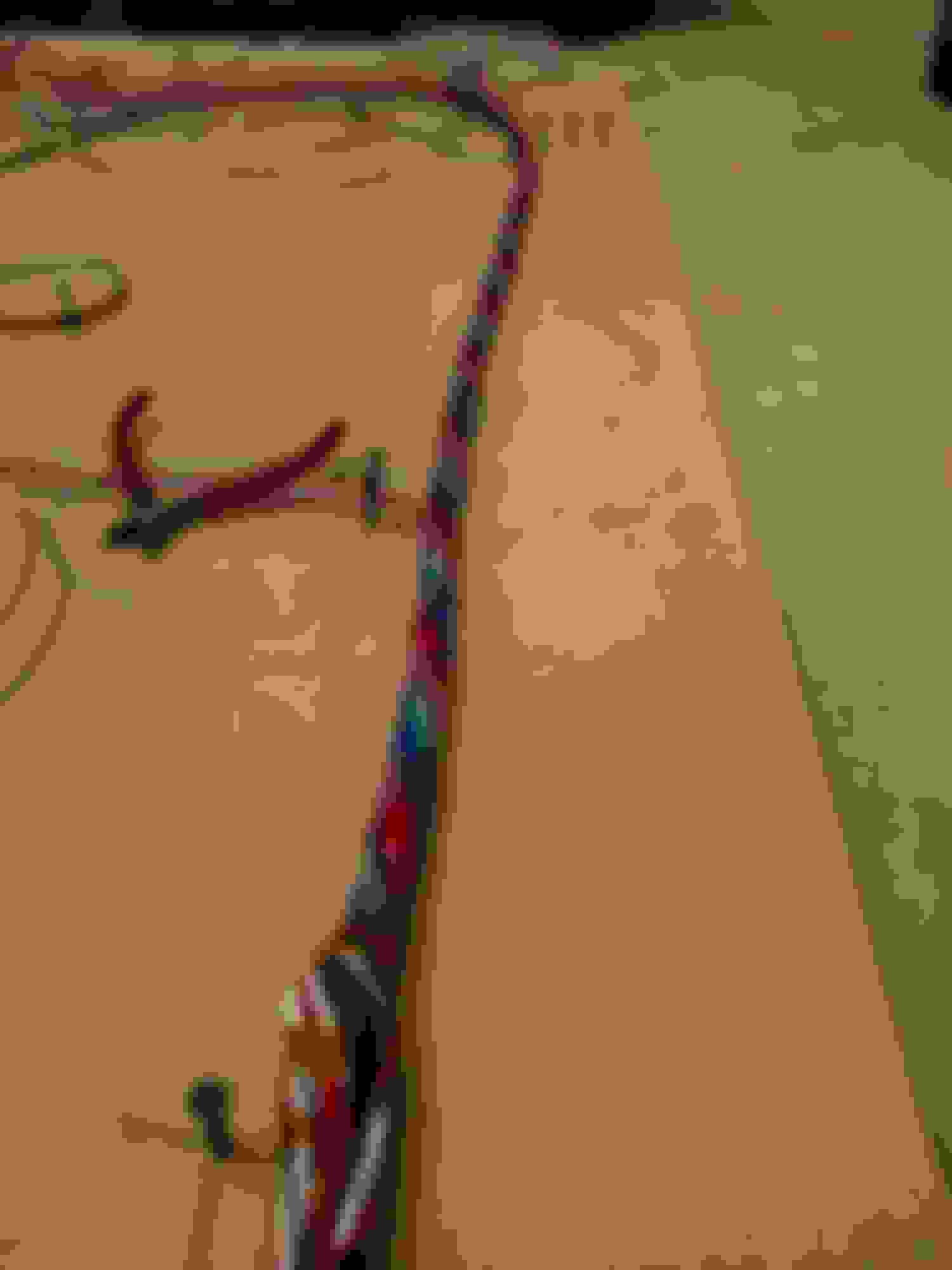
I made a oops here and had the purple wires coming out at the wrong breakout.
Luckily it turned out OK to get them back to the right spot.
I just rewired my chassis harness to the oem gauges/ stand alone needless to say.... my mind just blew up with this thread... amazing!!
thanks for sharing your work very inspiring!
I just rewired my chassis harness to the oem gauges/ stand alone needless to say.... my mind just blew up with this thread... amazing!!
thanks for sharing your work very inspiring!
Yo thanks! do you have a thread on your work on the gauges? I havent gotten to it yet, but someday i want to integrate the factory gauges to my stuff.
unfortunately i don"t.. but i found the wring diagram trough 13betc.com workshop manual wiring diagrams (s4)
your work makes it look like its a lot more fun building than driving.
unfortunately i don"t.. but i found the wring diagram trough 13betc.com workshop manual wiring diagrams (s4)
your work makes it look like its a lot more fun building than driving.
Ah, 10 4. Ha ha yea i'm certainly doing it for the project as much as for the end product. There's a lot cheaper, easier methods make a car work.
EB Turbo,
I forgot to mention that i had looked into lacing cord, but couldnt find anyone that would sell me less than a country mile of it so i decided to make do without. Using the narrow Kapton tape worked out pretty well although i'm sure its not as nice as using lacing cord.