I Bit Off More Than I Can Chew: A Drift Car
 05-18-20, 02:07 PM
#276
Senior Member
Thread Starter

tack and grind off any overlap


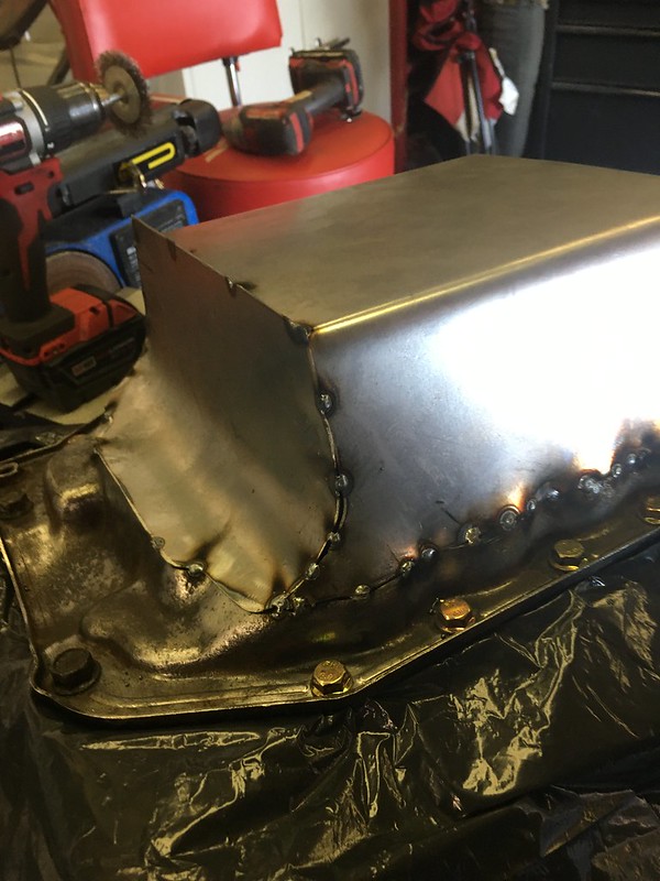
Before I got any further I wanted to know what I was looking at for oil capacity. I forgot exactly what I measured it at but it was something like 7 litres lol. Stock pan holds like 4.9L, and I’m adding a remote filter and cooler that I expect to add another litre at least.
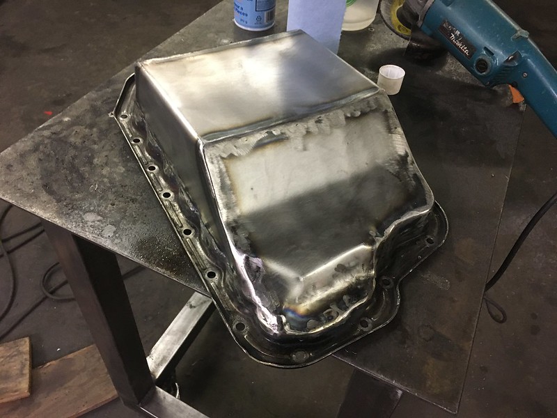
Then I went to fit it in the car and It hung below the subframe and hit the steering rack and the lines lol. Decided it would be easier to cut it off and start over. Modified my template and made a new one that fit much better


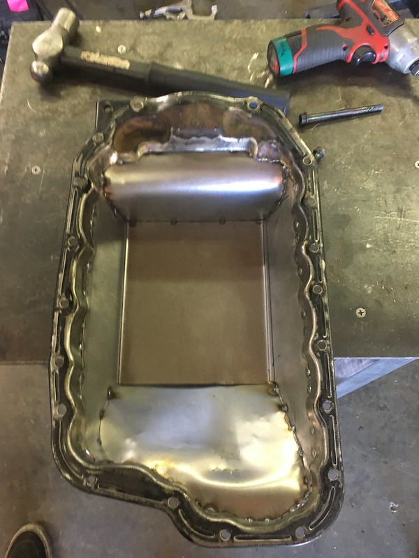
welded the inside as well. I am very confident there is no pin holes

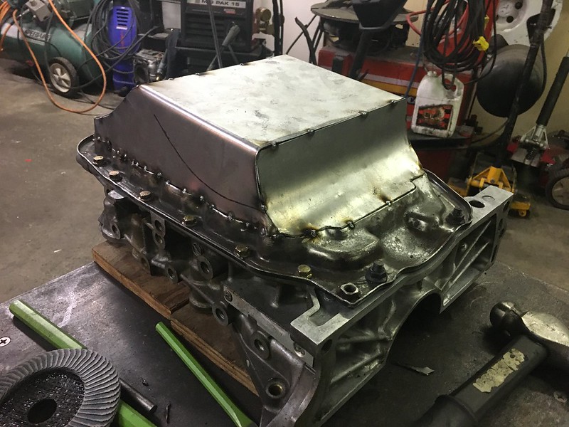
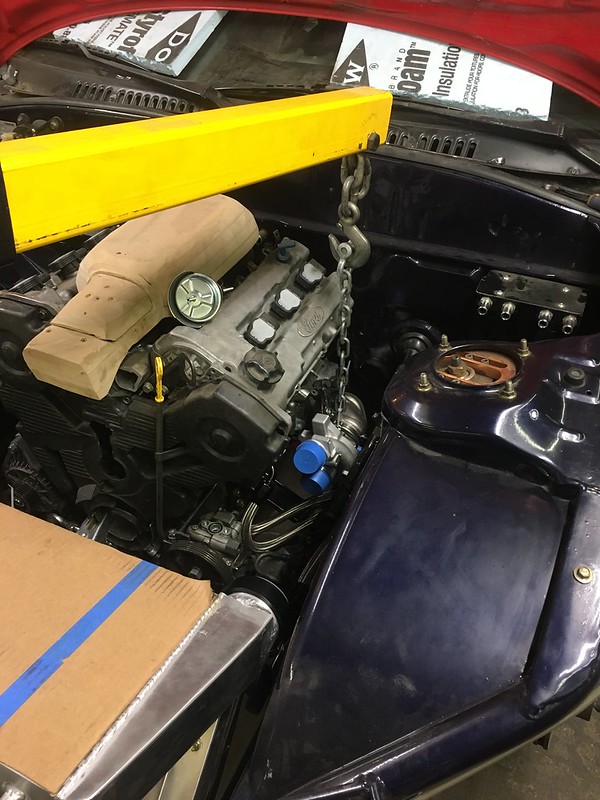
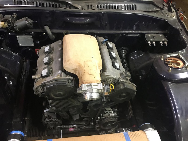
Put in some serious work to get the stock dipstick to work. Its in a really bad spot for this chassis, its at the front of the engine right above the steering rack. I really like the dipstick for some reason and always like it back when I had these engines in FWD form
some hammer and rewording and grinding later lol its done. Still need to baffle the the pickup, which I haven’t made yet and add a drain and a pair of turbo drains. But kinda holding off on the drains until the turbos are finalized, and I don’t want to put the drain right into a downpipes so ill hold off there too

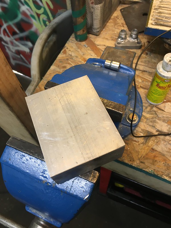
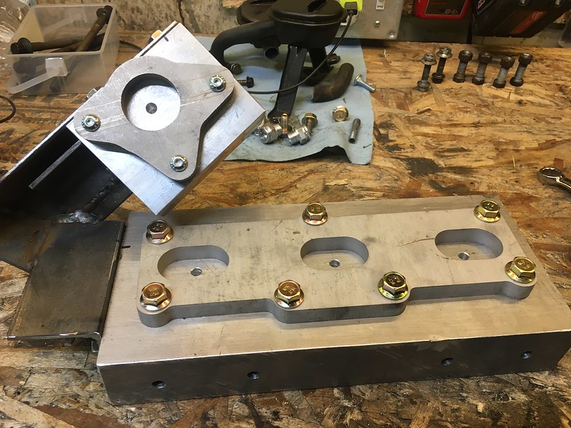
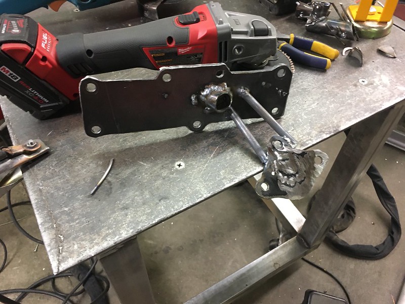
Quick little afternoon project was making the oil block mount.

 05-18-20, 02:08 PM
#277
Senior Member
Thread Starter
I have mockup pictures in a previous post

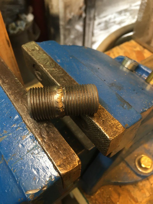
Got -10 AN weld on fittings in the mail, they were a little smaller then the ones I machined down so I used some filler rod to fit the space. then I screamed yolo and tried welding it myself cuz thats who I am as a person

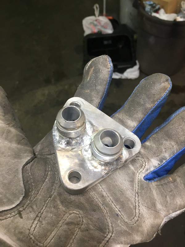
before you say “oh that doesn’t look that bad, lol it is. Burned through twice, tons of porosity and I ruined the threads. Tried welding the back and that went even worse.

So remade the whole piece lol

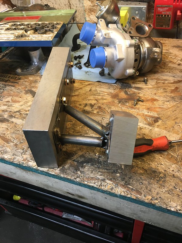
side to side comparison. Also note the tapped hole in the sides, one for oil pressure and one for the turbo oil feeds
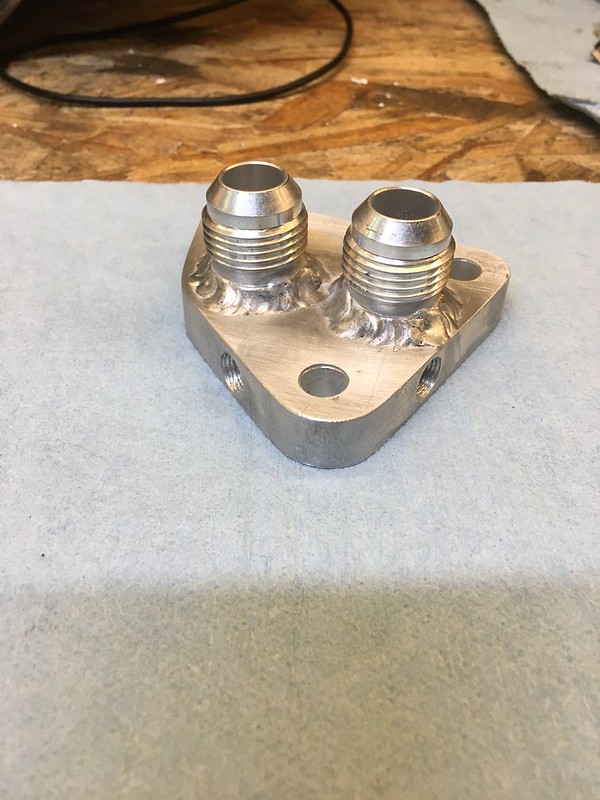


Hand ported to match the gasket. Hoping this improves flow and reduces pressure drop

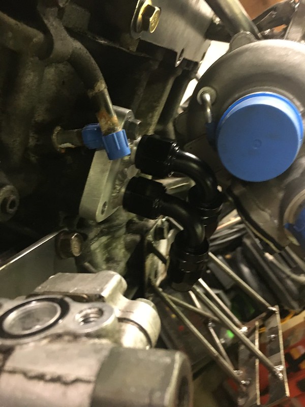

fits around the turbo decent, kinda close with the fittings on. Not planning of having to take it off very often
05-18-20, 02:11 PM
#278
Senior Member
Thread Starter
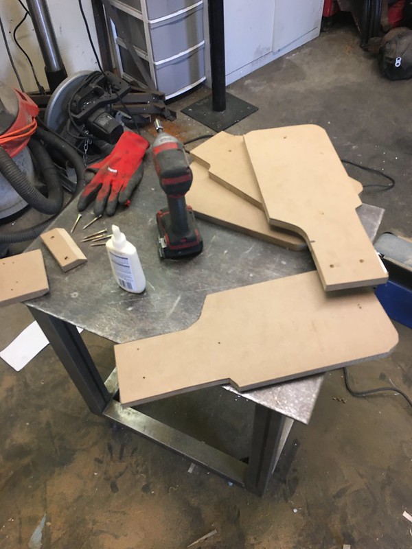
Made templates for the rad mounting. Going with the same design as the V8 where the side mounts are also ducting. Best idea I’ve had, 2 functions in 1 part combo


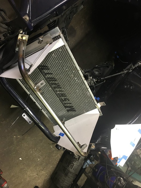

brought the templates to my buddy Travis’ shop where he has a shear and a hydraulic press brake and whipped these up.

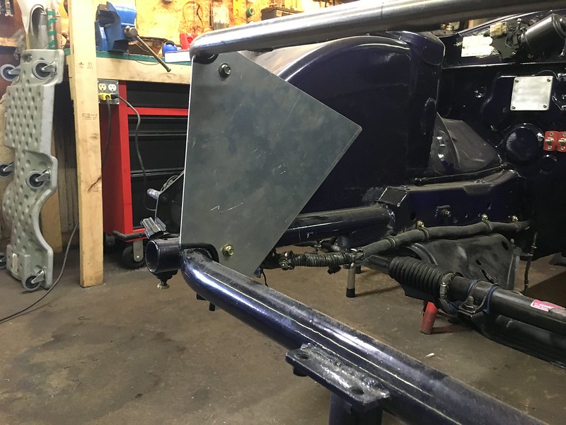
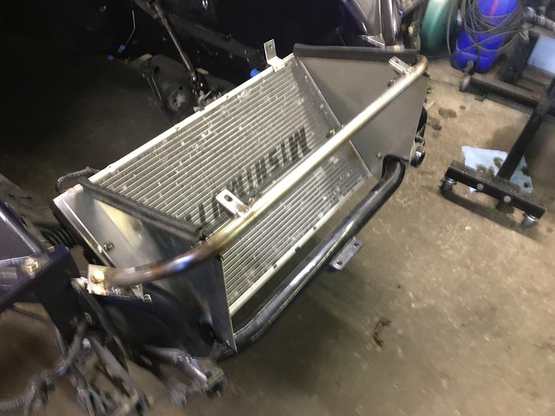
forgive the blurries. Intercooler seals on the top, I later cut a drop in the top to get the intercooler to clear the hood as it did with the mockup

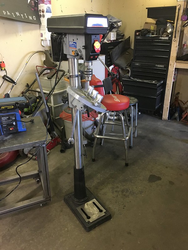
Happy birthday to me, my wife and parents bought me a sick drill press. I had been looking for a used floor standing decent one on craigslist for months and was either too late or it was too expensive. local tool place had this on sale so I bought the floor model.
Got the real turbos from Spectrum Motorsports

While I don’t know all the specifics these are a mixed matching of ecoboost turbos. The later years had a remote BOV and the early years are a smaller compressor or something. I just told Spectrum about my build specs and goals and he gave me this lol

They also got my flanges cut. They had the turbos flanges in CAD already so me and SCG didn’t have to make those which was nice

quick cleanup to fit the correct bolt through
brought the templates to my buddy Travis’ shop where he has a shear and a hydraulic press brake and whipped these up.
forgive the blurries. Intercooler seals on the top, I later cut a drop in the top to get the intercooler to clear the hood as it did with the mockup
Happy birthday to me, my wife and parents bought me a sick drill press. I had been looking for a used floor standing decent one on craigslist for months and was either too late or it was too expensive. local tool place had this on sale so I bought the floor model.
Got the real turbos from Spectrum Motorsports
While I don’t know all the specifics these are a mixed matching of ecoboost turbos. The later years had a remote BOV and the early years are a smaller compressor or something. I just told Spectrum about my build specs and goals and he gave me this lol
They also got my flanges cut. They had the turbos flanges in CAD already so me and SCG didn’t have to make those which was nice
quick cleanup to fit the correct bolt through
05-18-20, 02:13 PM
#279
Senior Member
Thread Starter
with flanges I can accurately make the jigs for the collector side
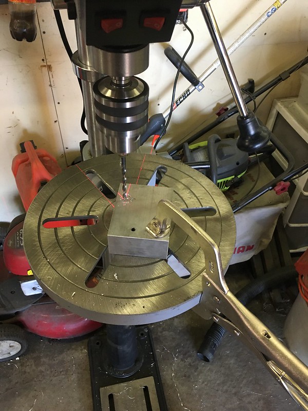
using my shiny new drill press
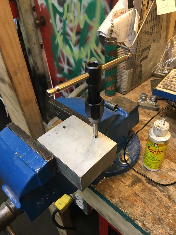
Found a tip online to use the drill press to by hand for starting the tap then finishing it by hand to ensure that its square


went one by one to make sure the hole enters as accurate as I could


didn’t take any process pictures but finally made sheet brake 2.0
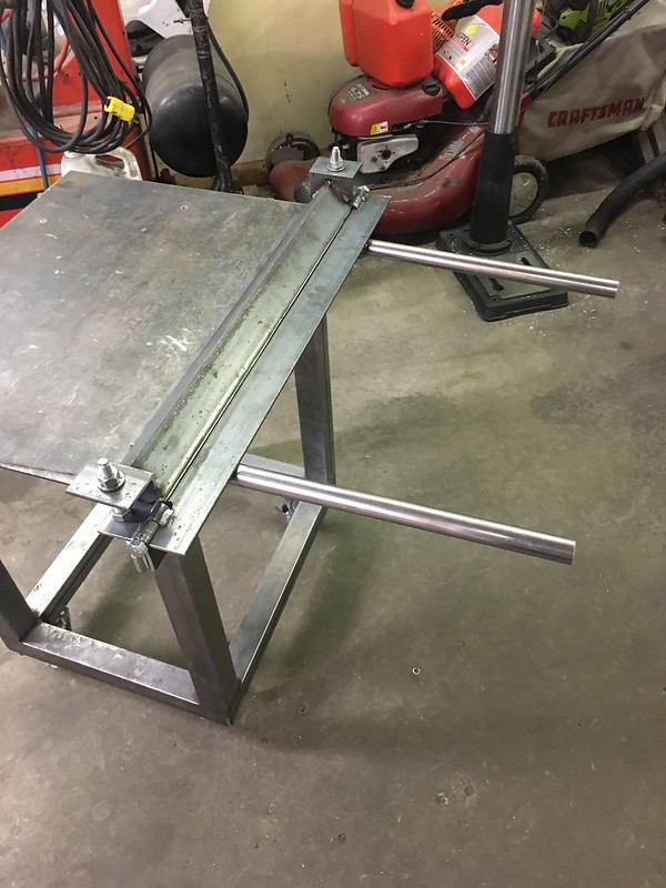
has an actual 25” bending area and uses thicker angle iron. I spent more time making sure the hinge alignment was mint

geared up to make the most overkill manifold jig, bending a 180* is actually pretty hard
 05-18-20, 02:13 PM
#280
Senior Member
Thread Starter

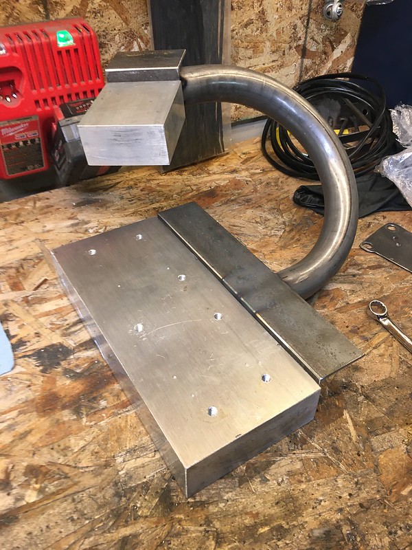
Idea here was to allow room for the tig torch while doing my best to keep it from heat warping


started to realize how little room I actually have to work with, at least If I’m doing anything other then a log manifold which was not the plan

Kris had some 1 1/4 steam pipe from a previous thing that I was using to get a rough idea for how much stainless to buy

added some holes for back purging, still need to tap these

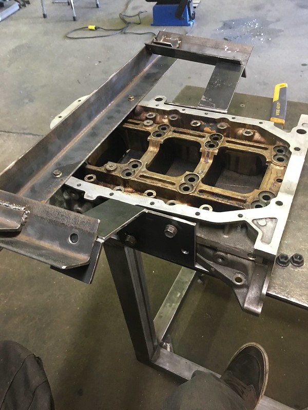
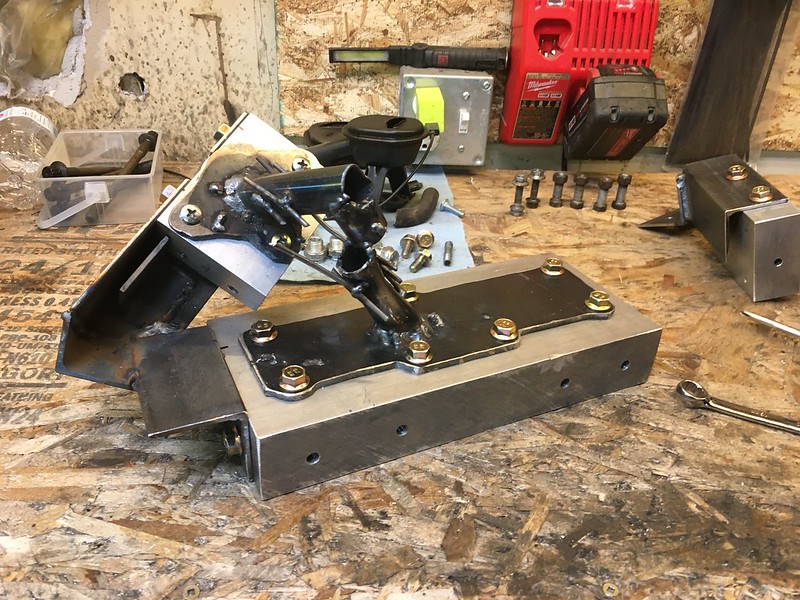
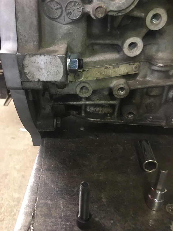
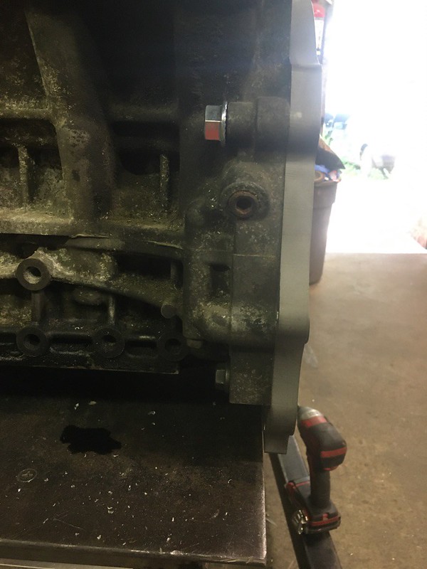
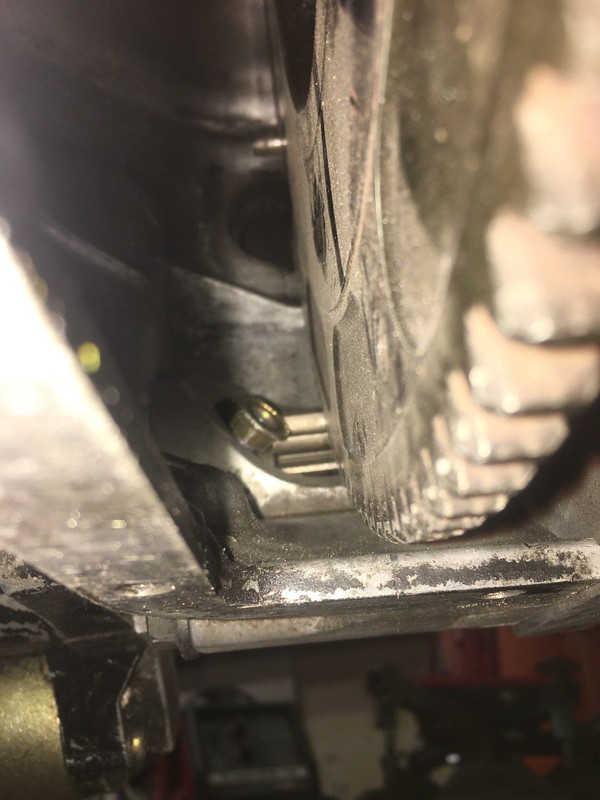
drilled holes to make taking the trans mount on and off actually do able. Didn’t like the way I couldn’t torque it before, as its not the best design lol

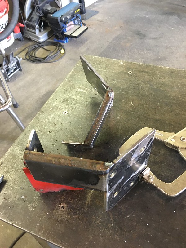
time to do real engine mounts
jig, paper templates, plasma cut
[img[https://live.staticflickr.com/65535/49906699473_4c8ef26a3e_c.jpg[/img]

drill some holes, mark some bends, make a slit to have it bend

 05-18-20, 02:14 PM
#281
Senior Member
Thread Starter

realize I marked the inside of the bend on the outside and after its bent it doesn’t fit right

cut off and trim the ends and weld it all up
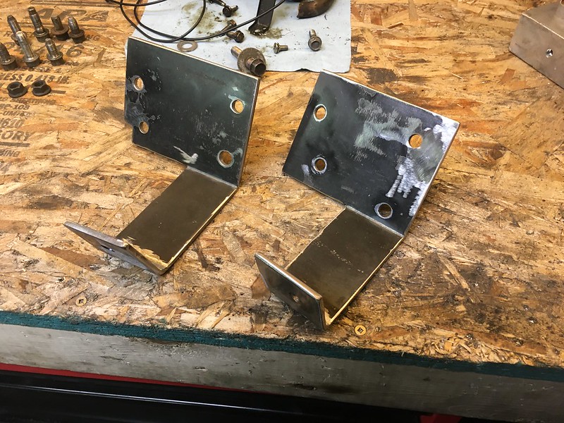
I always seem to choose to not have welds visible. This probably started back when I couldn’t weld very good but now I can weld passably but still choose to grind down welds


its 3/16” plate but just to be safe I added some little vertical pieces, which I also bevelled and ground flush

Neil at SCG let me sand blast them

gave them 2 coats of black

and done
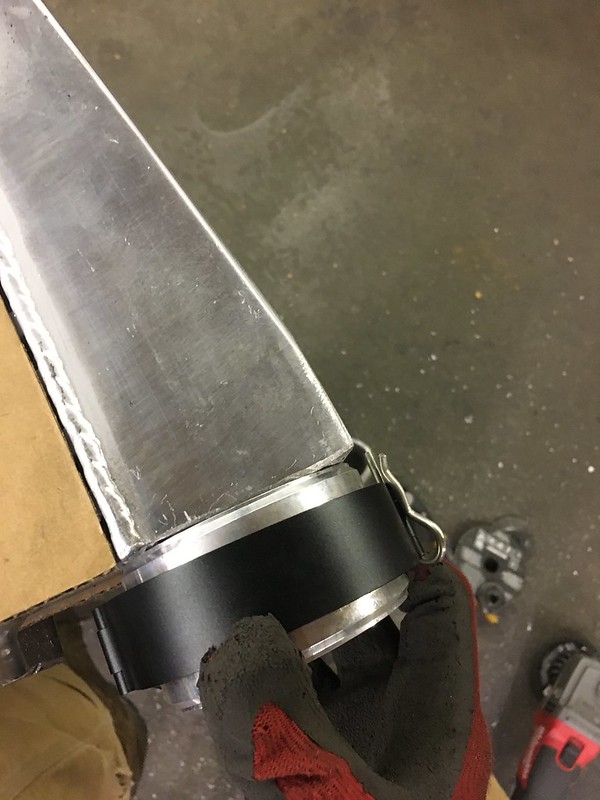
Bought QR Van Jen clamps on Ali a long time ago, they were a bit more then the hypertune rip off ones that use an allen bolt but other then the fact they use a cotter pin to lock them (I’ll try to find a detent pin like the Vibrant HD ones use) I like them. They seem to seal tight and don’t have any machining flaws. Probably should pressure test them before I go on record though lol

Bought a 3” for the side going to the TB (also 3”) and a 2.5 for the other side from the turbos which are 2” outlets

the intercooler is 2.5” so the 3” is a bit of a tough fit
05-18-20, 02:15 PM
#282
Senior Member
Thread Starter

I don’t want any shavings in there ruining my engine later on so the solution I came up with is a shop vac on blow


have some small gaps to fill but I can probably get a more experienced welder to help right?
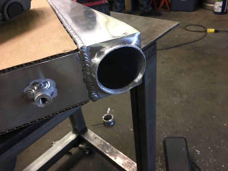
the 2.5” side fit up was much easier


fit check before going any further
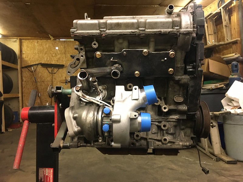
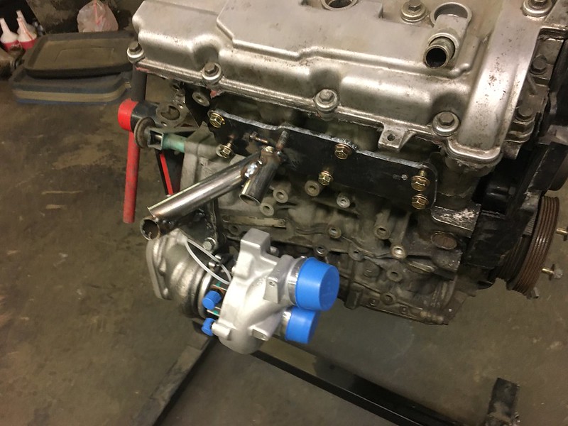
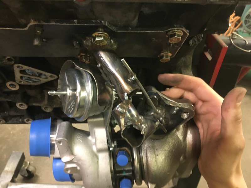
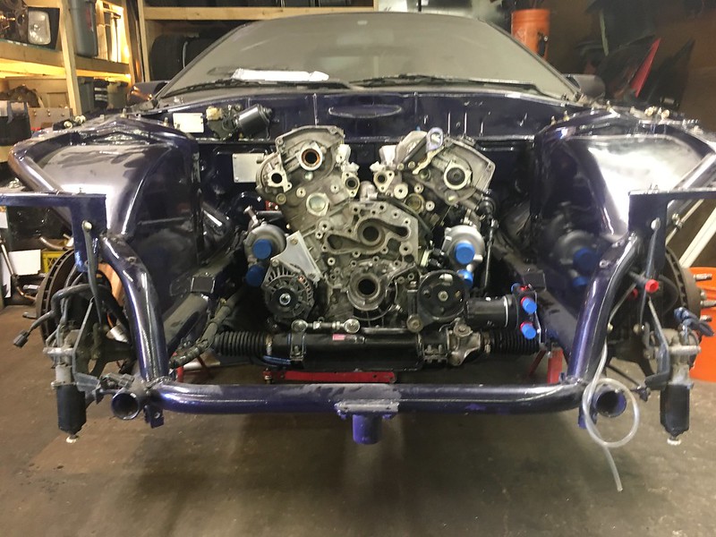
So around now is the time when Im discussing turbo waste gate actuator with Spectrum, and theres less wiggle room then I had thought. The OEM location is really tall and basically into the heads on my engine, but as I understand to get proper seal and such the rod needs to be perpendicular with the flap. We are going to do a heim on the flapper arm to let me get the actuator diaphragm closer to the compressor housing (still need to maintain some room from the exhaust to prevent melting it though)
so heres a bunch of fitment photos


 05-18-20, 02:15 PM
#283
Senior Member
Thread Starter
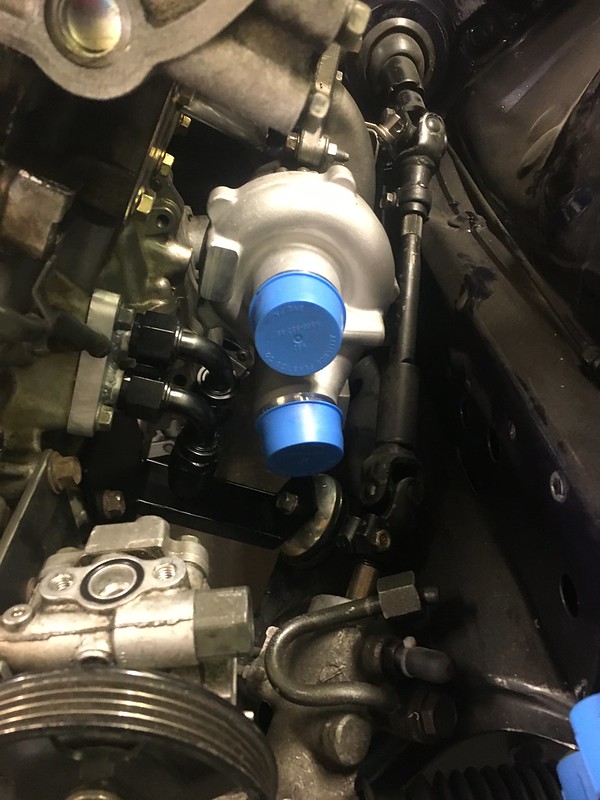

what is really not ideal is how close the waste gate actuator is to the steering column, which has dictated the placement of the turbo already (even though the waste gate likely won’t open that far)
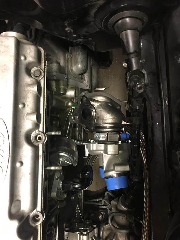
so went back to an idea I had a while ago which was to flip the turbos side to side and bottom mount them. So I cut another set of manifold flanges (quick and easy with the water jet flanges as templates and the plasma cutter) kept the old ones just in case and started playing around with flipping the turbos

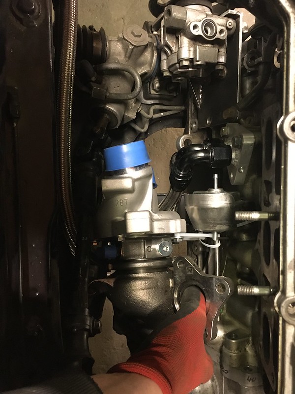

engine crane is the best way to do this

 05-18-20, 02:16 PM
#284
Senior Member
Thread Starter


there is more room here than it seems. spent like 2 evenings getting the drivers side turbo positioned just right. The passenger side took 1.5 hours


 05-18-20, 02:16 PM
#285
Senior Member
Thread Starter
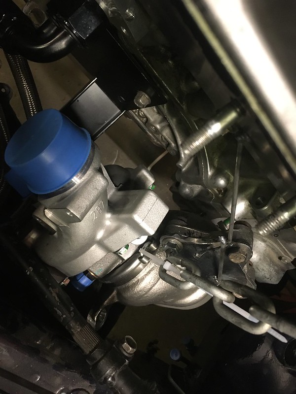
much more actuator room now, oil drains are still above the pan, less downpipe material and the best part is I can do equal length now


built the jigs and ordered material
kinda missed this in earlier mock ups but this isn’t good lol. Made a new one that moved it away by a bit. (don’t have pictures)
some random progress shots

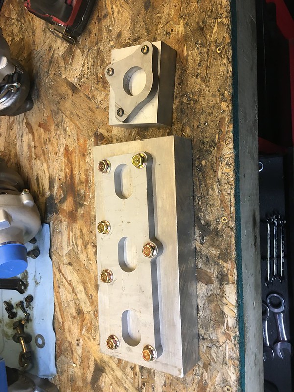
got the real deal adapter plate back from water jet. Made a few small changes this time, some of the holes will be tapped and bolted to the engine from the engine side. Currently its with the machinist getting worked on in his free time

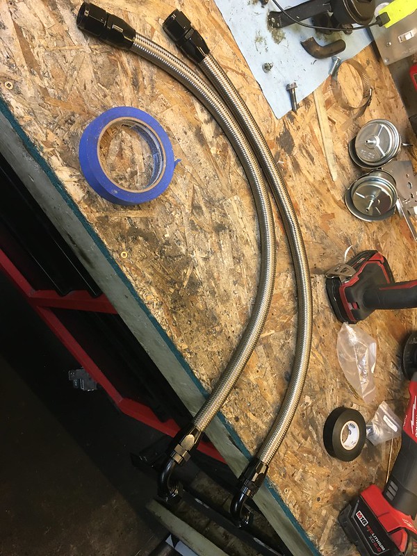
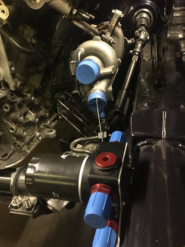
made -10 oil lines for the engine to remote filter
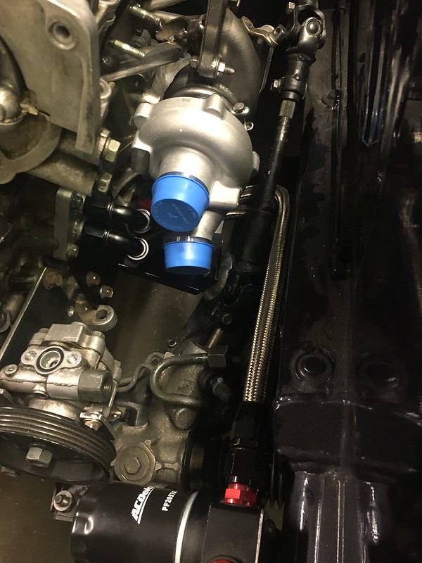

as my wife would say “this is an aesthetic”
very much like the look of black fittings, braided stainless and red plugs
built the jigs and ordered material
kinda missed this in earlier mock ups but this isn’t good lol. Made a new one that moved it away by a bit. (don’t have pictures)
some random progress shots
got the real deal adapter plate back from water jet. Made a few small changes this time, some of the holes will be tapped and bolted to the engine from the engine side. Currently its with the machinist getting worked on in his free time
made -10 oil lines for the engine to remote filter
as my wife would say “this is an aesthetic”
very much like the look of black fittings, braided stainless and red plugs
05-18-20, 02:17 PM
#286
Senior Member
Thread Starter

screamed yolo again and took a crack at welding the intercooler


screwed up the weld on top of the 3”, like the most in view weld on it. Will have to grind it down and weld the top again and hope that goes better
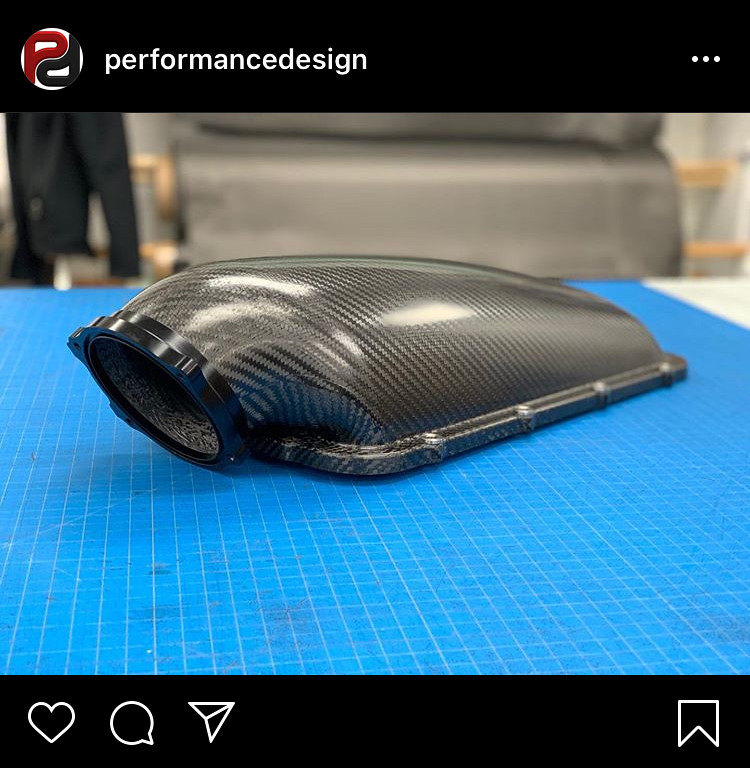
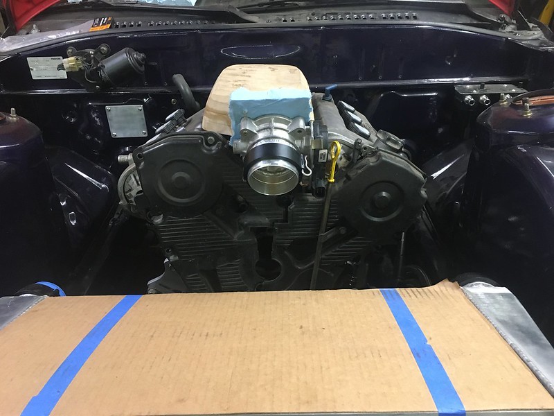
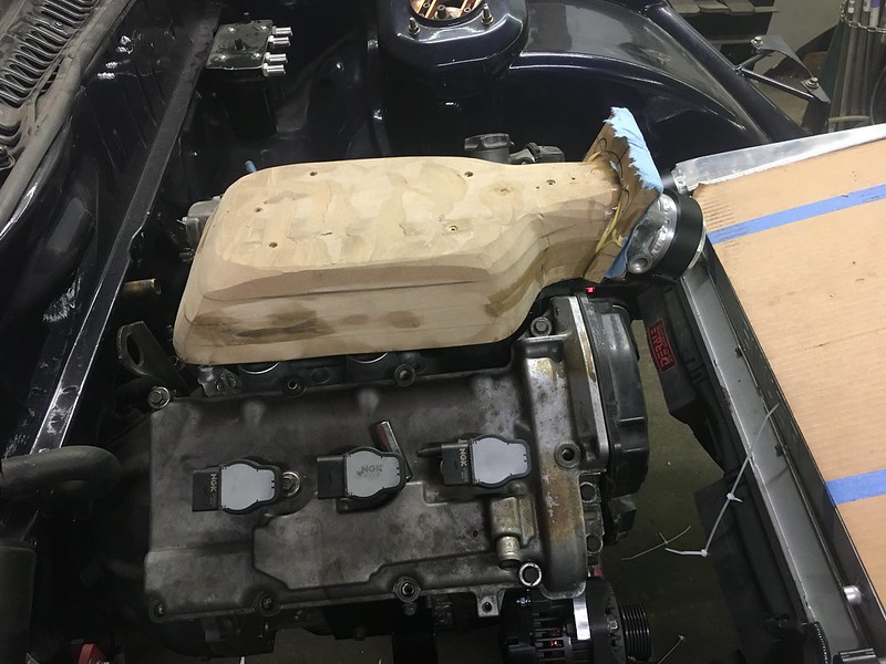
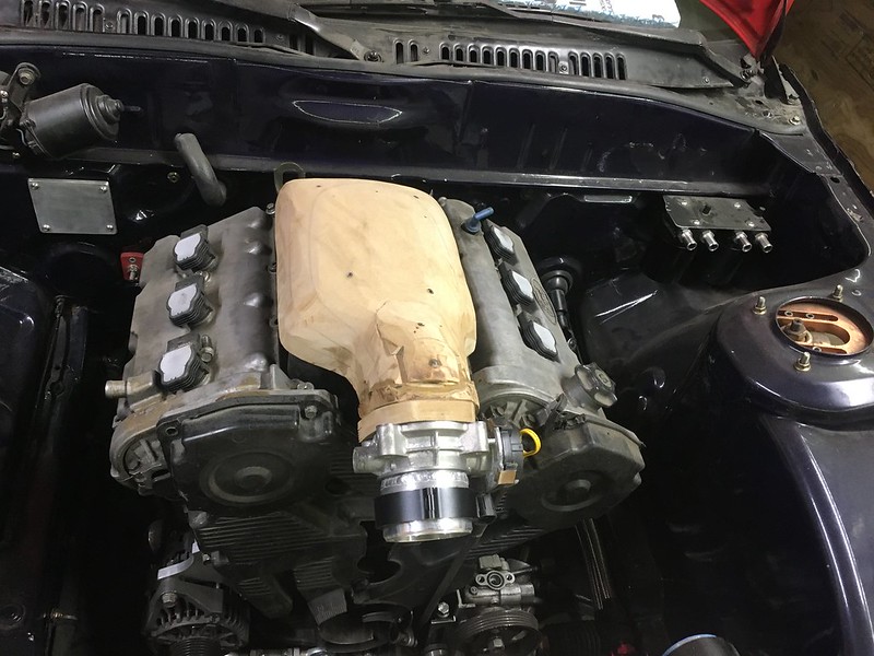
started on the intake manifold. Dream here is to do this in carbon fibre, I found this company Performance Design after I had started but it gave me a good goal in mind as I really like the way theirs looks. They make a few of these, one is a top for the Holley high rise and mid rise intakes. From what I can gather They use pre-preg carbon and 2 pieces at least on the outer layer. I don’t have an autoclave or a vacuum pump so pre-preg is out. At the moment I’m unsure if I should make it a top shell or be risky and try a 2 piece mould and use a little spray tack to hold a second piece (or one if I can figure out the shape) upside down while I do the rest of the layers. I started on making a plug for it, getting the shape to look nice and clear the hood etc


that 45 zip tied to the timing cover is to clear the water outlet from the heads, which I might change
05-18-20, 02:18 PM
#287
Senior Member
Thread Starter

on that, can get the coolant temp and pressure sensors to fit under the intake manifold. the upper part will be held on with hose and clamps so removing it won’t be hard if something needs to be changed. Still debating on how to do the water outlet. either under the throttle body or under the timing belt to give the throttle body more room but then I’ll need a bleed line because there will be a high point
since welding cast aluminum had gone ok thus far (and since I discovered washing welds lol) I welded the van jen onto the throttle body

at first I was being careful about not letting it get too hot for fear of melting the sensor, but 30 seconds of googling while waiting for it to cool showed me how easy it was to remove and reassemble
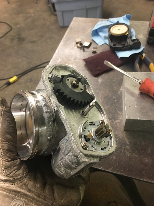


smoothed out the inside. I must have warped the housing a little bit because with the motor out and letting it snap back on the spring the blade would get stuck. Not sure if that is always how it was but I shaved a little off the areas it was catching (mostly the top and bottom furthest from the shaft. I also drilled out the holes to all be M8 bolts.
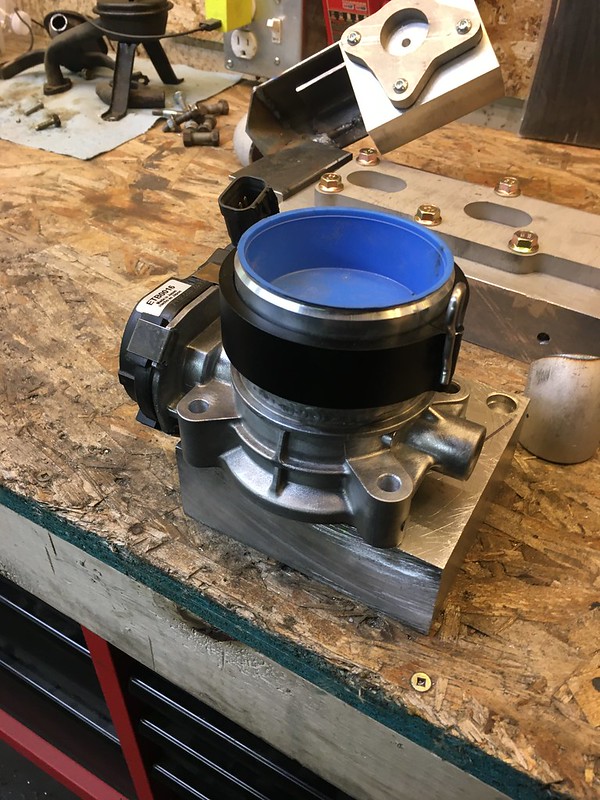
cleaned everything up and lock tighted the blade bolts (V important) and all done.
further messing with intake manifold shape. The pipe joining the intercooler and TB doesn’t have as much room as Id hoped. I really hate pie cuts and want to avoid anything that resembles that but I’ll need a pretty tight CLR 3” 90 bend to meet them
oh yeah somewhere in there I remade the mould lol


 05-18-20, 02:19 PM
#288
Senior Member
Thread Starter

hat tip to my buddy Miguel for the hookup on the OEM Ford turbo gaskets. all the research said these are the only ones to get. Im not sure if they are considered reusable, being MLS and all but at $126 for the lot they sure are to me
Got my order of stainless and messed around a bit. This is really satisfying and I see why people get so into it. Stainless seems like a finicky thing to weld nicely though, as usual prep is key and its very intolerant of mistakes. I was trying a few different techniques to see what they did, no filler root only, root + cap and single pass with flller. With the thickness of sched10 root without filler and then a cap pass with seems to yield the nicest looking welds consistent with what I see done on high end manifolds.
As usual the drivers side is the most difficult to fit. Once I have a complete manifold I’ll just more or less copy it to the passenger side. The turbos sit nearly identical side to side and the passenger side has little to no space constraints so copying the drivers side for rough shape and more importantly runner volume shouldn’t be hard. I always thought that equal length manifolds meant the runners were equal length, but never understood how that was measured. Using the longest path? or the shortest or the CLR of a bend? Well turns out what matters is volume, which makes far more sense to me

Its a 3D jigsaw puzzle but also a math problem balancing the runner lengths.
[img[https://live.staticflickr.com/65535/49906680508_d92cf965f5_c.jpg[/img]
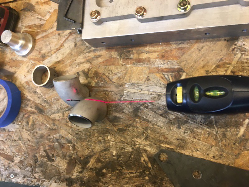
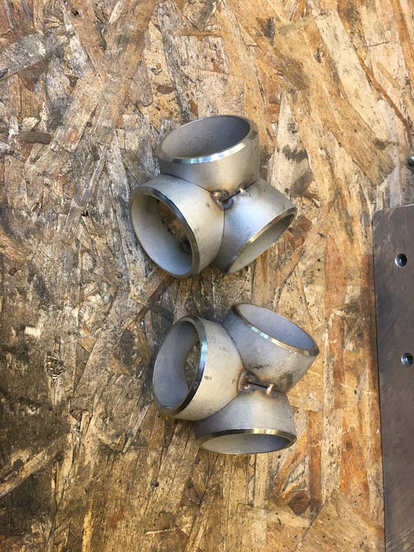
First thing I was told to do is make a collector and make sure it fits
modified the drivers side jig yet again

And big surprise its not going to be that easy. I’m going to spend my long weekend figuring out how to make a collector with 90’s as using straight pieces will have the 90 hitting the steering rack. Im probably not going to be able to have studs on the head like factory if I actually want to remove the manifold.
Should be getting some big pieces figured out here, but probably (sadly) a few months away from firing it up. Hopefully the Canada/US border opens soonish or I find some other way of getting parts across without getting hosed
 05-18-20, 11:26 PM
#290
Senior Member
Thread Starter
thanks man, I bought the -10 stuff from Aliexpress. I'm pretty sure most of is the same as Performance World from Mopac, which is also a good place to buy fittings and line
06-21-20, 05:52 PM
#292
Senior Member
Thread Starter
thanks! funny enough I actually end up on Formula SAE forums fairly often when doing research for this build. some really good explanations of foundational concepts on there
06-21-20, 05:52 PM
#293
Senior Member
Thread Starter
Been doing nothing but listening to old music on repeat so lol nothing really to add there
scrapped the collectors, unfortunately a lost of time lost but thats all part of the fun
I use a laser whenever I can, I just like laser beams. Made it easier to get the cut and fit really tight. Im not the one welding these so I want to make it as easy as possible and that means tight fit ups.


rinse repeat.

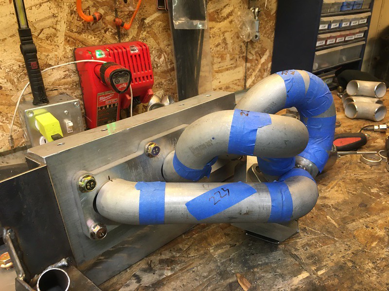
much better fitting near the steering column


This kinda made for an awkward manifold that had really long runners and hard to get the bolts and get in and out of the car. My OCD wasn’t happy

sooooo minor change
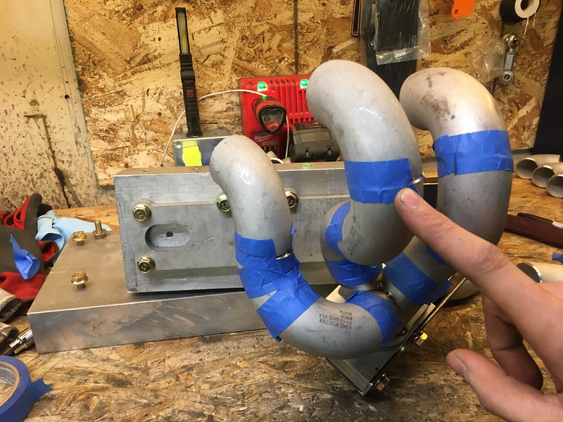
tack them in a symmetrical way

to make fitting them easier, as tape holds it it place pretty well but you can adjust it once its taped, I cut some thin aluminum tube to make like spring holding thing

worked really well actually
scrapped the collectors, unfortunately a lost of time lost but thats all part of the fun
I use a laser whenever I can, I just like laser beams. Made it easier to get the cut and fit really tight. Im not the one welding these so I want to make it as easy as possible and that means tight fit ups.
rinse repeat.
much better fitting near the steering column
This kinda made for an awkward manifold that had really long runners and hard to get the bolts and get in and out of the car. My OCD wasn’t happy
sooooo minor change
tack them in a symmetrical way
to make fitting them easier, as tape holds it it place pretty well but you can adjust it once its taped, I cut some thin aluminum tube to make like spring holding thing
worked really well actually
06-21-20, 05:53 PM
#294
Senior Member
Thread Starter


got the runners fit up nicely. Funny thing I learned is that equal length manifolds really mean equal volume. So all my runners are really close, not sure what acceptable tolerance is but they are within 5%

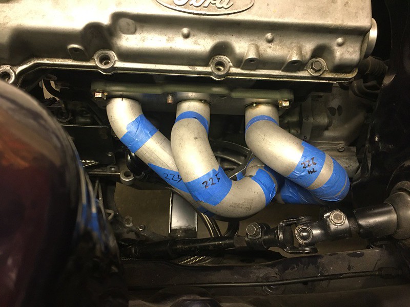
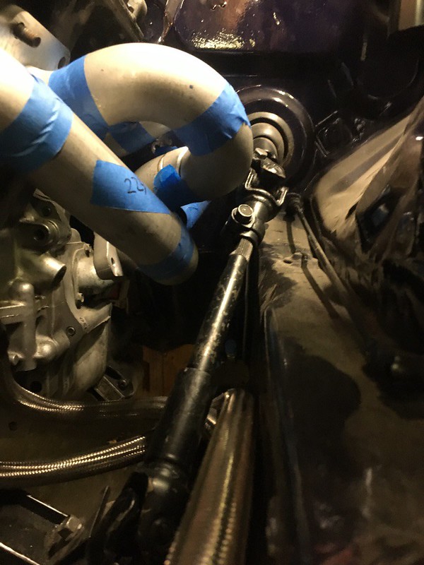
Fits in the car well, I can get the manifold on and off without having to lift the engine or anything silly. I dont know about with the turbo on yet but should fit fine. I can use one stud but no more, Mazda only used 2 studs so I’ll try bolts and one stud and we’ll see how that seals.
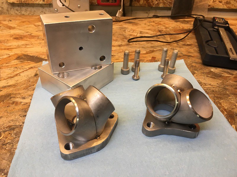
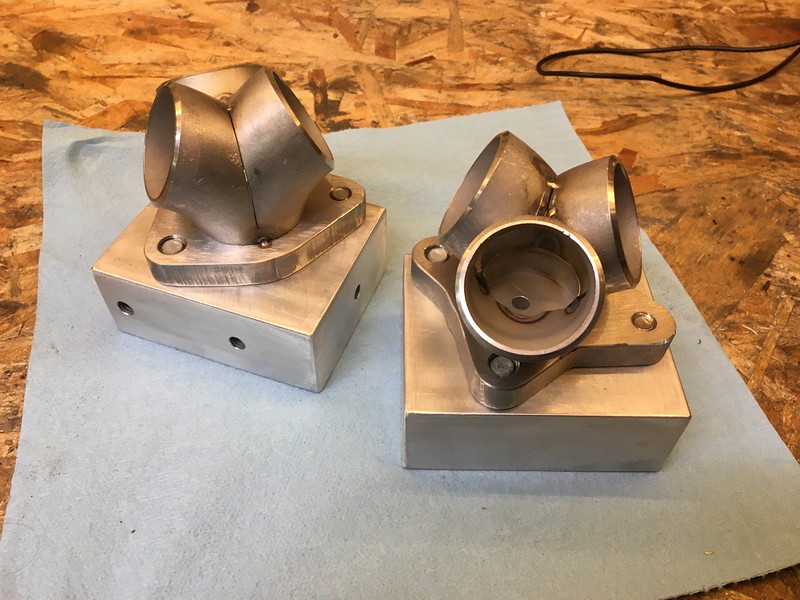
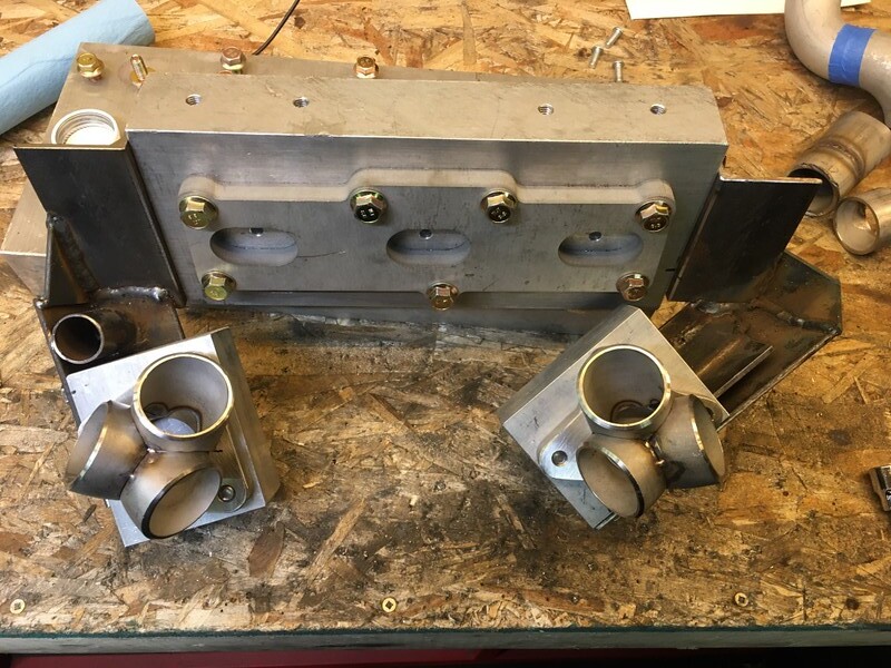
finished the welding blocks, got the hardware sorted and dropped them off with my buddy Travis to weld them. Tapped a 1/4” barb for back purge, he later told me to add a diffuser to make the gas flow straight

Got the real deal adapter plate back from cutting and machining. Made a few small changes besides the hole size on the M12 bolts to the block

I gave up trying to find a countersunk allen head in M12x1.25.
M12x1.75 is much more common and easy to get. One side on the engine block isn’t even threaded, and the other side is threaded but theres nothing behind it.
drill it out and put a nut on the back
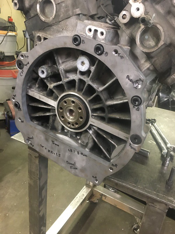
whole thing bolts up perfectly
06-21-20, 05:54 PM
#295
Senior Member
Thread Starter
also got some less then common hardware M10x1.0 for the flywheel adapter.

Its actually a reasonably common thread for flywheels but not in allen head and in the length required for the adapter
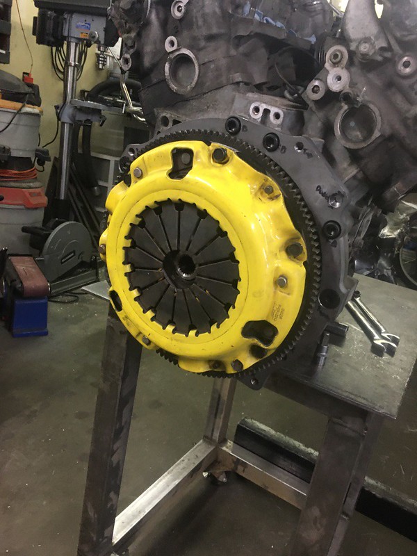
flywheel bolted up
So for the first time I have the engine and transmission bolted together with the clutch lined up and it all fit
starter engagement is good, I locked the spur gear all the way out to check

pilot bearing is right on the end of the input shaft, like full engagement though. Prefer this because the adapter sandwiches the pilot bearing between the crank and it self.

turns out T2 and NA rx7 trans use different slave cylinders. Well barely

Thankfully the T2 ones are cheap and available
The whole thing fits, I’m blown away. Big thanks again to Neil at SCG for all the help. Arguably the biggest piece in making this build functional. Also thanks to Hose for his help machining all things I can’t lol.

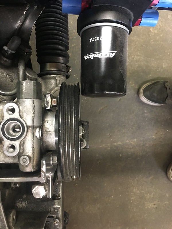
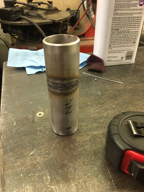
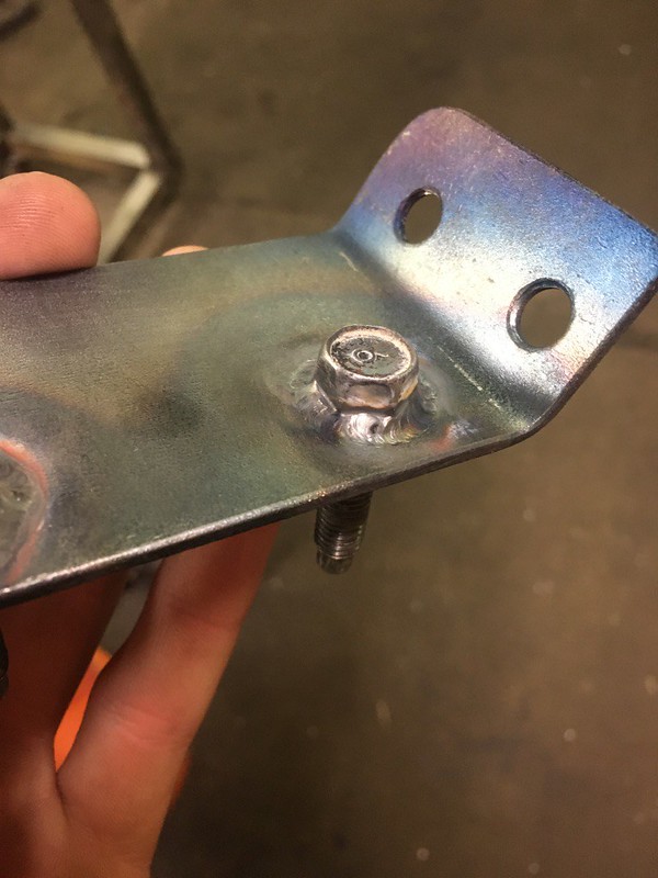
another small thing I didn’t want to get held up by later, I used the adapter from the filter block already on the fuel filter because it didn’t come with one. So I had to make one and while I really don’t like the idea of welding this but it will have to work for now
used a bolt to get it good and aligned
practiced my tig skills. round objects are hard

reamed out the inside

and threw it in there
went back to finishing the trans mount since the trans was out of the car again
06-21-20, 05:54 PM
#296
Senior Member
Thread Starter

tig’d with no filer and really like how that looks. I’m sure using filler is proper or whatever
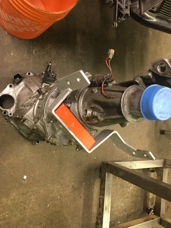
however since I fitted it back in the car, between the engine mounts and now the trans mount it doesn’t quite fit perfectly so I’ll need to cut and tweak that a bit
a kind of issue has been the fuel rails. So I had found these Honda J30 V6 rails had the same injector spacing, but as far as mounting goes it was going to be a challenge and also ugly. I was ok with that somewhat because it was going to be hidden under the intake manifold. But they didn’t exactly fit the injectors I had, so my options were to get new injectors ($$), modify those rails to suit and hate the end result or just buy rail stock and make something I’d be happy with.

Mopac had a FAST 24” rail in stock, wasn’t far off the cost of ordering rail stock from the states

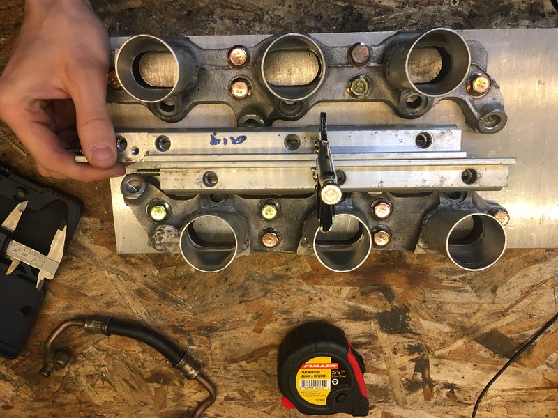
double checked all the measurements on the stock rails and laid out and drilled the new ones after cutting them in half

I measured and ordered tooling to replicate the ID adapters as close as possible, including the 10mm step to locate the injectors

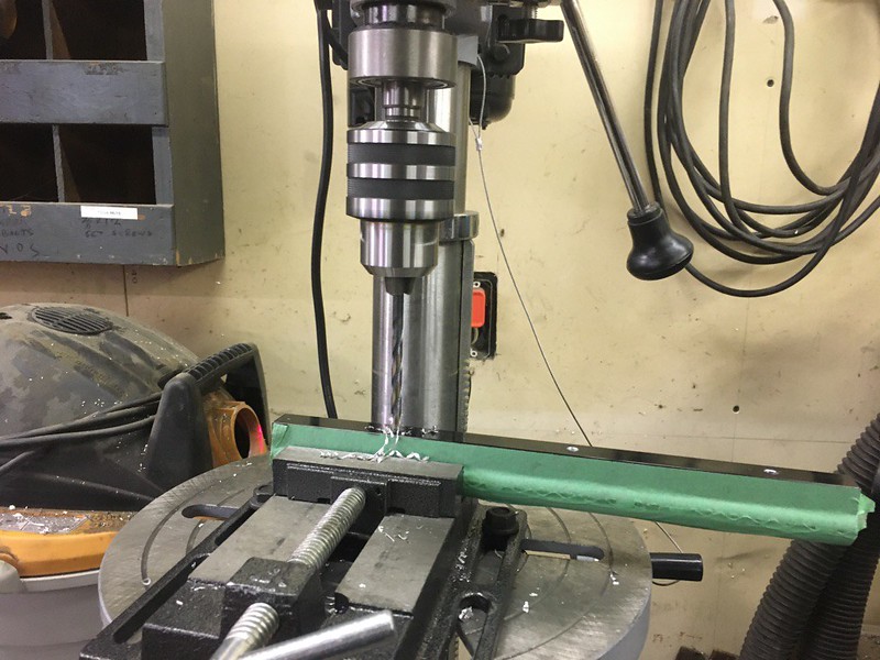
did a test run on some bar stock just to make sure it all works. After some measuring it looked like I was going to have to max out what space I had and drill the rail as deep as I could and the manifold as deep as it could be

So after much setup and struggle to get it aligned using the tool I made


and then drill the rails
06-21-20, 05:55 PM
#297
Senior Member
Thread Starter


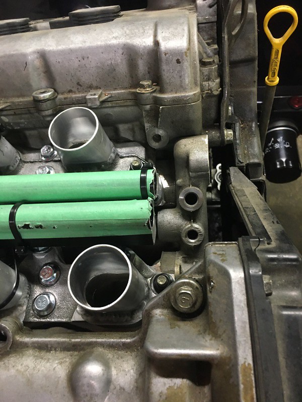
Mockup with the injectors in place to be able to measure for mounts

the tricky part here was going to be joining the 2 rails. I was thinking banjo bolts and a machined block until I fit it in the car and realized how little space I had. Then the banjo bolts that fit the bore have a head size thats too big, so now I’m working on an idea with a 180* fitting…


then I spent an entire evening making mounts for the fuel rail just to find that I made a measuring error. The rails sit on a 30* angle relative to the flange and where I measured the offset distance was much closer then where the rails actually sit. But now I know what they are supposed to be lol


Thread
Thread Starter
Forum
Replies
Last Post
calum.anderson36
Build Threads
7
12-21-18 07:34 AM