I Bit Off More Than I Can Chew: A Drift Car
 11-12-19, 06:43 PM
#251
Senior Member
Thread Starter

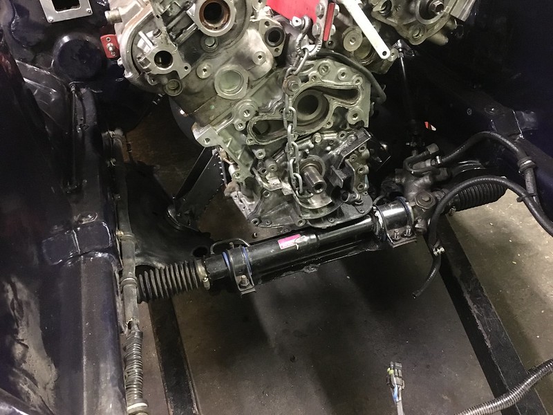
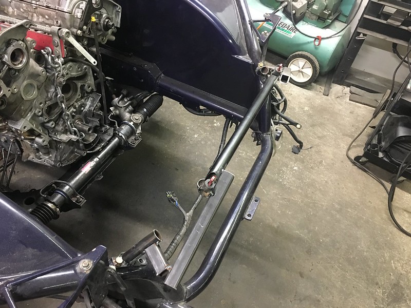
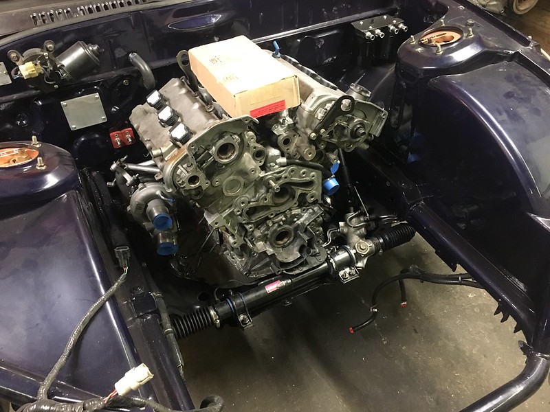
the real big issue that could arise if the engine was too close to the steering rack is the oil pump pickup tube would be on top of it. I was hoping the front of the oil pump housing would just be overtop of the rack just as with the 13B. At this point I had good hood clearance and more firewall clearance then I even needed. Good room from the steering rack and good room from everything else for turbos and downpipes.


Now the transmission had a slight issue even in the stock position. The speedo cable hits the transmission mount, remember this is an auto chassis and the crossmember mounts are already in the wrong place, but I was basing where the trans sat off my memory and pictures I could find of doing a manual conversion. I don’t really understand how this hits as I don’t remember it being a problem before and looking at Xccesive manufacturings crossmember for swaps it doesnt look like it should be a problem.
Thankfully I have like 4 of these cables sitting around for some reason, so I trimmed the collar piece to the bare minimum on one in rough shape and that wasn’t too bad to do.

So I started moving onto the rest of the big pieces


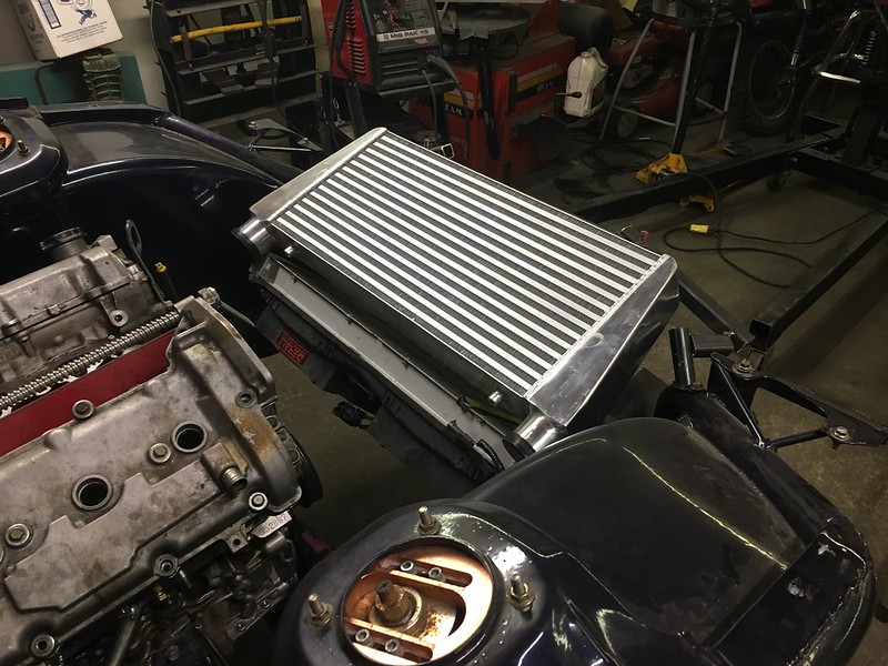
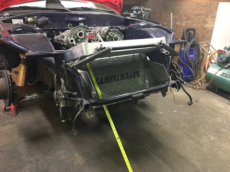
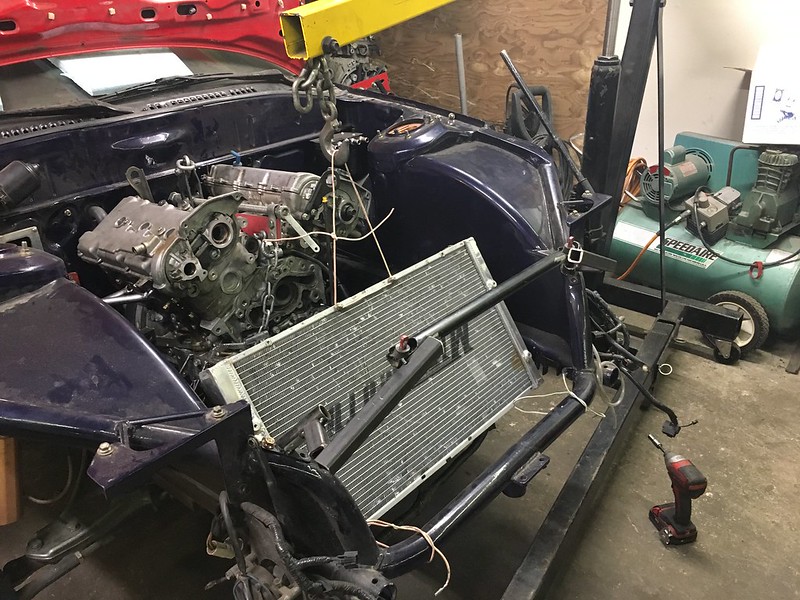
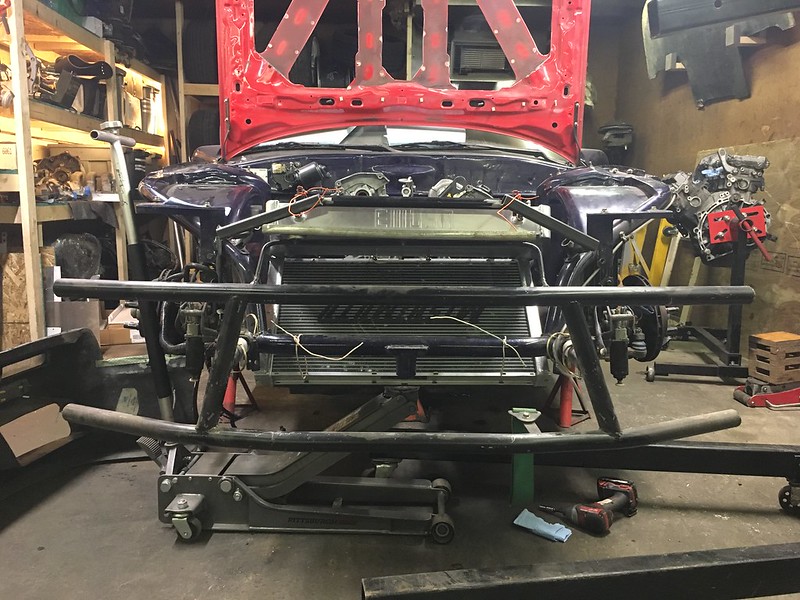
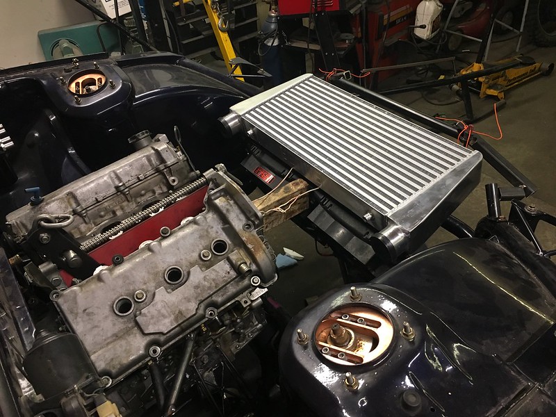
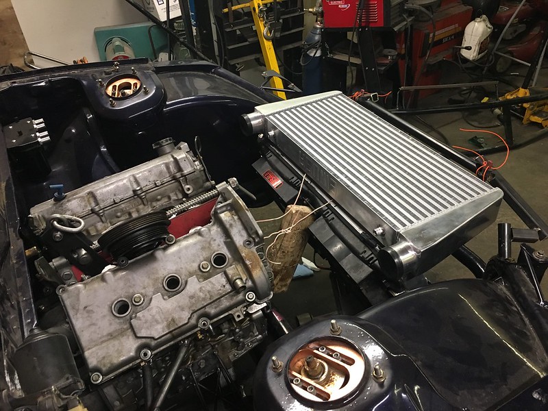
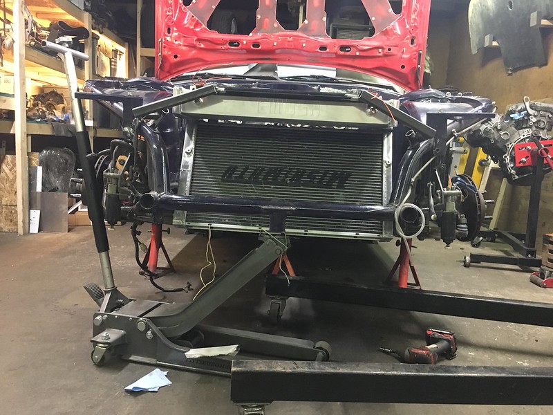
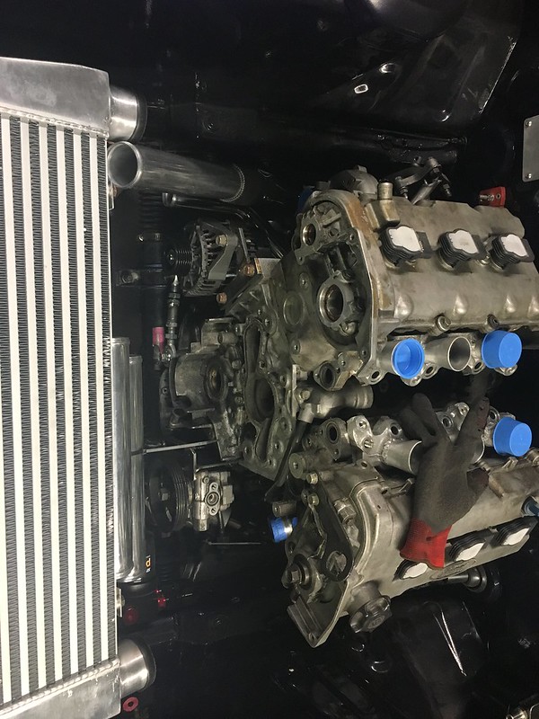
Intercooler was one I had laying around, it has a big hole in the bottom so its also junk but helps to mock up. Rad is the same mishimoto just flipped upside down to put the outlets on the passenger side. Better suited I think, I don’t want to have too much going on on the drivers side as it will get chaotic quickly. Aesthetics are still very important to me but I also want it to be easy to work on and functional.
While I chewed on all that and the options for where everything would go I got a new toy.
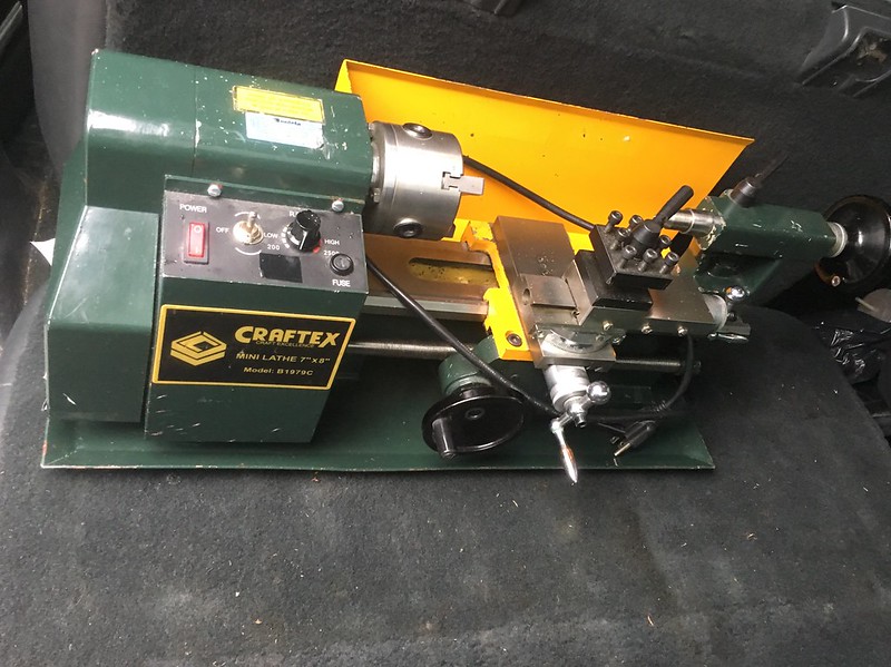

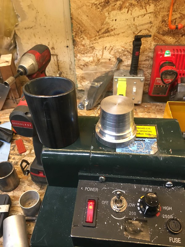
Got a smoking deal on a mini lathe, I have been super interested in owning a lathe for some time. I now understand why machining is its own trade as theres a lot that goes into doing it correctly. After much research I settled on trying to grind my own HSS bits and it appeared to work decently so far.

But then I started the machine at full speed, this is a belt driven lathe and they need to be slowly sped up. So I shredded the belt and haven’t used it since. Ordered 3 wrong belts so far lol, I have another on the way that I now think is the correct size/tooth
As time goes on I’m more and more into the idea of just making my own parts. Theres certain things where I’d like to be able to buy at any given parts store but I find that aftermarket parts kinda suck half the time and with the right tooling I think I can do better. I may even have to do it twice before I’m happy with it but thats all part of the fun for me. I’m not on some fake reality TV show with unrealistic deadlines or anything. I’d like to get a mill next and that would almost give me the ability to make anything I can think of. And if its too big or complex I know where to outsource stuff to. Jack of all trades, master of one maybe lol. Id like to be good at wiring.

I also broke the lighting strip on my side of the garage soon it was time to spend a bit on actually being able to see what I’m doing. These 2 LED lights made such a difference. I want 2 more lol.
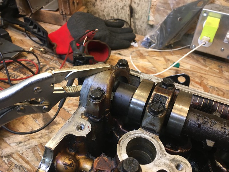
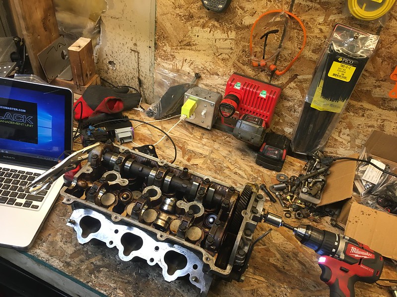
Now after much deliberation, I had decided to move the engine back 1.5 — 2” and hopefully lower. I had the room for the oil pan depth, I could still get at the clutch slave and had room for everything that needed to run behind the engine. But this all kind of hinges on the cam sensor. I’d really like to find a way to spin up a cam on a bench with the sensor mounted and see if I get a usable signal pattern.


Moving onto another potential issue, fuel rail/injector clearance.
Now the transmission had a slight issue even in the stock position. The speedo cable hits the transmission mount, remember this is an auto chassis and the crossmember mounts are already in the wrong place, but I was basing where the trans sat off my memory and pictures I could find of doing a manual conversion. I don’t really understand how this hits as I don’t remember it being a problem before and looking at Xccesive manufacturings crossmember for swaps it doesnt look like it should be a problem.
Thankfully I have like 4 of these cables sitting around for some reason, so I trimmed the collar piece to the bare minimum on one in rough shape and that wasn’t too bad to do.
So I started moving onto the rest of the big pieces
Intercooler was one I had laying around, it has a big hole in the bottom so its also junk but helps to mock up. Rad is the same mishimoto just flipped upside down to put the outlets on the passenger side. Better suited I think, I don’t want to have too much going on on the drivers side as it will get chaotic quickly. Aesthetics are still very important to me but I also want it to be easy to work on and functional.
While I chewed on all that and the options for where everything would go I got a new toy.
Got a smoking deal on a mini lathe, I have been super interested in owning a lathe for some time. I now understand why machining is its own trade as theres a lot that goes into doing it correctly. After much research I settled on trying to grind my own HSS bits and it appeared to work decently so far.
But then I started the machine at full speed, this is a belt driven lathe and they need to be slowly sped up. So I shredded the belt and haven’t used it since. Ordered 3 wrong belts so far lol, I have another on the way that I now think is the correct size/tooth
As time goes on I’m more and more into the idea of just making my own parts. Theres certain things where I’d like to be able to buy at any given parts store but I find that aftermarket parts kinda suck half the time and with the right tooling I think I can do better. I may even have to do it twice before I’m happy with it but thats all part of the fun for me. I’m not on some fake reality TV show with unrealistic deadlines or anything. I’d like to get a mill next and that would almost give me the ability to make anything I can think of. And if its too big or complex I know where to outsource stuff to. Jack of all trades, master of one maybe lol. Id like to be good at wiring.
I also broke the lighting strip on my side of the garage soon it was time to spend a bit on actually being able to see what I’m doing. These 2 LED lights made such a difference. I want 2 more lol.
Now after much deliberation, I had decided to move the engine back 1.5 — 2” and hopefully lower. I had the room for the oil pan depth, I could still get at the clutch slave and had room for everything that needed to run behind the engine. But this all kind of hinges on the cam sensor. I’d really like to find a way to spin up a cam on a bench with the sensor mounted and see if I get a usable signal pattern.
Moving onto another potential issue, fuel rail/injector clearance.
 11-12-19, 06:44 PM
#252
Senior Member
Thread Starter
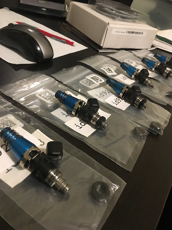
A friend of mine was going to larger injectors so he sold me his ID1050X. This is another area where I believe its worth it to spend some money. These are some of if not the best injectors money can buy, they are also much bigger then I will need pretty much ever lol. But they can handle small accurate amounts of fuel insuring idle quality blah blah blah. I read too much lol.
I can take the blue spacers off, these injectors were for an RB26, and get them pretty short. I’ll need to machine the lower intake manifold to allow these to fit somehow… still working on the best way to do that.

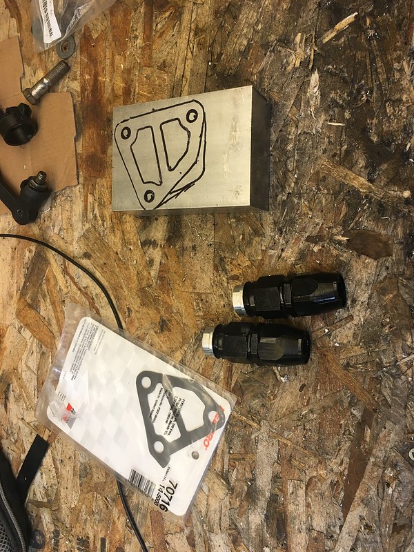
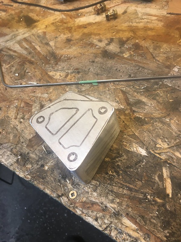
Scored me some giant aluminum blocks to make into welding fixtures for the intake and exhaust manifolds. Found a local place that picks up and re sells scrap material from machine shops and such. 1/2 price of my local metal supermarkets so you bet I’ll be shopping there going forward.


Bought some transfer punches and man that it was way to do this kind of stuff.


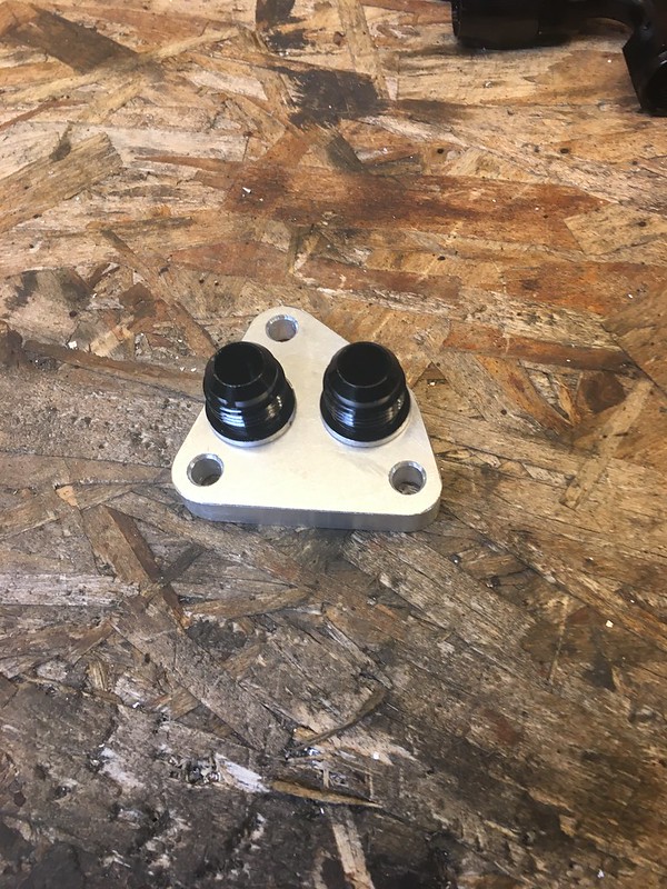
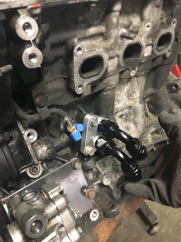
Same time I went to a local hydraulics place and spent way too much on JIC/AN plugs and hose plugs. Really like how these look when servicing stuff but more importantly they keep dust out and prevent stuff from leaking out of lines all over the floor.
Modified my engine mounts to be able to slide the engine back and forth


Much happier with how this looks and clearances up front and around where all good. Then I decided to lower the whole thing a bit which meant I cut up my engine mounts and basically started over.
I can take the blue spacers off, these injectors were for an RB26, and get them pretty short. I’ll need to machine the lower intake manifold to allow these to fit somehow… still working on the best way to do that.
Scored me some giant aluminum blocks to make into welding fixtures for the intake and exhaust manifolds. Found a local place that picks up and re sells scrap material from machine shops and such. 1/2 price of my local metal supermarkets so you bet I’ll be shopping there going forward.
Bought some transfer punches and man that it was way to do this kind of stuff.
Same time I went to a local hydraulics place and spent way too much on JIC/AN plugs and hose plugs. Really like how these look when servicing stuff but more importantly they keep dust out and prevent stuff from leaking out of lines all over the floor.
Modified my engine mounts to be able to slide the engine back and forth
Much happier with how this looks and clearances up front and around where all good. Then I decided to lower the whole thing a bit which meant I cut up my engine mounts and basically started over.
11-12-19, 06:44 PM
#253
Senior Member
Thread Starter

Borrowed the neatest digital level from Neil. I did a bunch of reading and had a better understanding of setting up driveline angles. So I yanked the shifter turret that was in the way and put the engine where I wanted it with the engine crane and started over.


I found an easier way to build temp engine mounts was to take some thin round rod and easily cut to length tack it on both ends, do the other side then check all your measurements again. I got a friend who had the subframe and driveshaft out if his car to measure the distance from the bottom of the shift surround plate on the tunnel to the middle of the output shaft to give me an idea where the trans should be. I learned that engines are usually tilted back 2-4* and that the pinion angle and the output shaft angle should be within one degree. The digital level had a false Zero feature so I didnt even have to do math.
After I got the engine sitting where I wanted it, engine mounts welded up strong enough to hold position ensuring I had room to slide it back and forth a bit I bent a mockup for the transmission crossmember before cutting the real deal out of 1/4” plate.


Before I final weld it I want to make sure the shifter it going to line up.

The factory T2 trans shifter turret actually looks pretty easy to modify. I read a thread where a guy shortened it to the absolute minimum, he cut and welded everything closer to the bolt holes. Then redrilled the hole in the selector rod and cut it shorter (in that order). You can find it on Rx7club with some searching. What I found instead was that NA Miata and FB Rx7 use the same style of turret.

This is a NA miata (moar miata parts lol) and it looks really close. I’m tracking down one locally, though I’ll probably have to buy a whole trans to get it. I should be able to swap the selector rod as well and not have to modify anything.

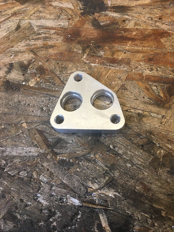
Got the first bunch of wiring connectors and such I ordered and some hardware from McMaster Carr I ordered for the adapter plate. Somehow I can never seem to spend less than $100 there, I always like buying extra hardware I guess.

Got the final adapter piece back from water jetting. Need to sandblast it and get it tapped (I’m not going to risk hand tapped 5/8” plate lol) and counter bored for the bolts and transmission dowels.

Borrowed some mock up turbos from Spectrum Motorsports. Chris has been a huge help and given me some solid advice so far, he’s been working with these Borg Warner turbos lately so not only did he have some junk housings kicking around he has a lot of data to go on.
11-12-19, 06:45 PM
#254
Senior Member
Thread Starter

but since they aren’t mine I’m taking care of them

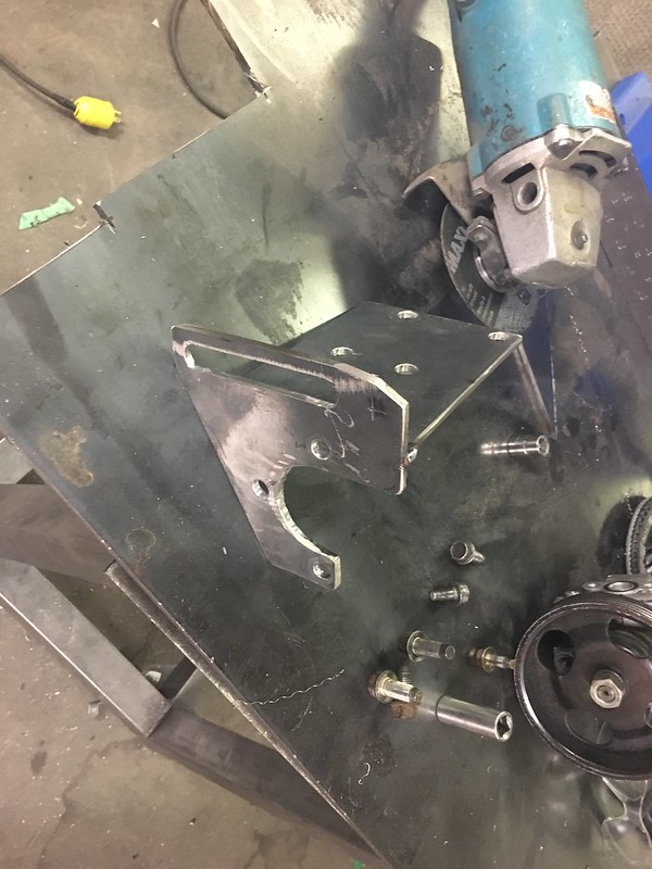
traced out and cut some plates to place the turbos and build the fixtures from.

In a dream world these would be symmetrical and my manifolds would be symmetrical buuuuuuuut no


Those hawk eyed of you will notice that I actually placed these on the old motor mounts but I have verified them with the new ones and so far everything clears.
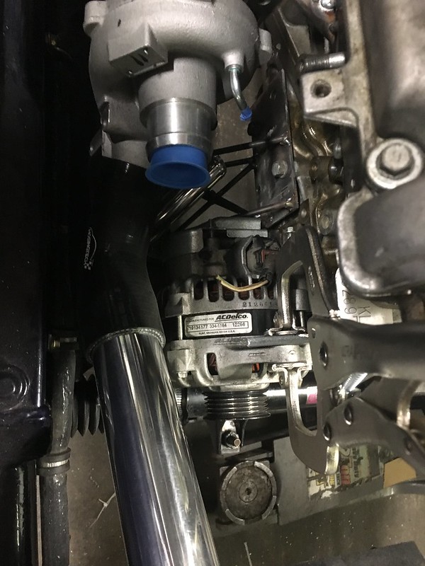
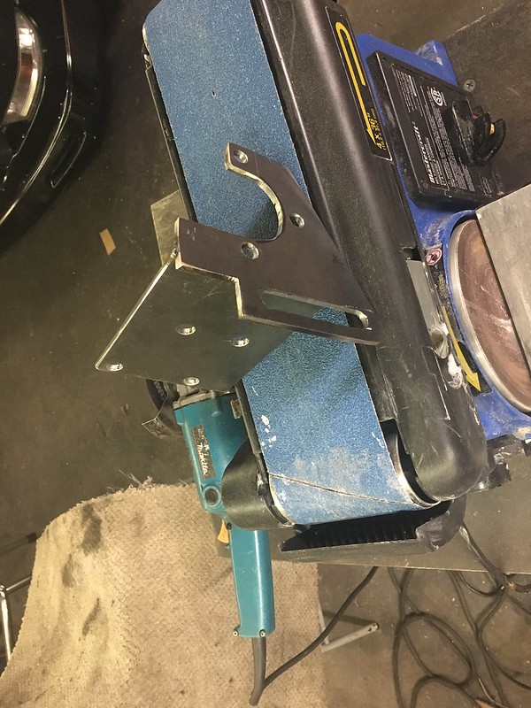
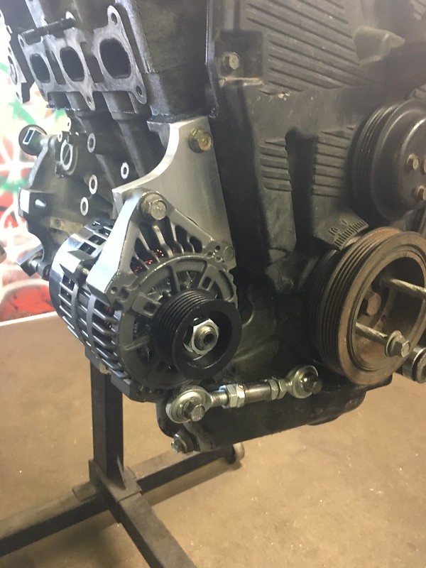
I also decided to make more work for myself and not use the factory tensioners or brackets (might use parts of them) to place the alternator and power steering pump.They are on the opposites sides of where I want them for this chassis, the power steering line is going to be 3” long this way and the bulkhead stud for the alternator is on the passenger side. They were important to have roughly in place for getting the turbo positions correct. I also threw the factory oil filter pedestal in there just to make sure it would fit if the one I intend to build doesn’t work out for some reason or another. Its big and in the way so ideally I won’t be using it and instead be using the remote filter with an oil cooler this time.
11-12-19, 06:46 PM
#255
Senior Member
Thread Starter
Another note, I was sliding the engine/trans back and forth to accommodate the bellhouse adapter thickness. My current plate is a 1/2” shy of the real thing so I was measuring off the crankshaft to the true front and moving depending if I was working on the trans or the engine side of things.
The Borg turbos are cool because they can have the water cooling ports on the same side of the turbo, I’m using them facing the block and planning to utilize thermal siphoning. I have mapped out where to get water feed and return as well as oil feed and return for both and ordered the necessary fittings from China. I’m doing my best to plan ahead as the shipping times are usually a month.


Now stuck between a “7” mount or a “V” mount (> mount?) setup. For sure want to do it this way, I’ve always planned it this way. Drivers side turbo will have to cross to the passenger side pre intercooler. It will also have to pass probably under the bell house/ oil pan area in order to meet up with the exhaust as theres a starter in the way on its side. Almost like there was never intended to be an exhaust down pipe there or something…
Really like the way both look from certain angles. The V mount to me makes it seem like theres more room in the engine bay. But the 7 means I can fit an even bigger rad in if need be. Instead of a 14” height I could go up to a 19” and still clear below. Id like to try and reuse this rad, try and save some costs somewhere.
It’s taken me over a week to find time just to type this out, so I already have more to add to it. When I have time anyway lol.
Questions? fire away.
The Borg turbos are cool because they can have the water cooling ports on the same side of the turbo, I’m using them facing the block and planning to utilize thermal siphoning. I have mapped out where to get water feed and return as well as oil feed and return for both and ordered the necessary fittings from China. I’m doing my best to plan ahead as the shipping times are usually a month.
Now stuck between a “7” mount or a “V” mount (> mount?) setup. For sure want to do it this way, I’ve always planned it this way. Drivers side turbo will have to cross to the passenger side pre intercooler. It will also have to pass probably under the bell house/ oil pan area in order to meet up with the exhaust as theres a starter in the way on its side. Almost like there was never intended to be an exhaust down pipe there or something…
Really like the way both look from certain angles. The V mount to me makes it seem like theres more room in the engine bay. But the 7 means I can fit an even bigger rad in if need be. Instead of a 14” height I could go up to a 19” and still clear below. Id like to try and reuse this rad, try and save some costs somewhere.
It’s taken me over a week to find time just to type this out, so I already have more to add to it. When I have time anyway lol.
Questions? fire away.
11-30-19, 05:57 PM
#256
Junior Member

Tyson, i enjoyed reading through your swaps. I admire your persistence for not settling on something mediocre. I haven’t used any of the swap pieces yet as I had to pull the T5 to drill the clutch fork. Question - what is the name of the metal shop that sells recycled material?
keep up the good work,
Myles
keep up the good work,
Myles
12-01-19, 09:01 PM
#257
Senior Member
Thread Starter
Tyson, i enjoyed reading through your swaps. I admire your persistence for not settling on something mediocre. I haven’t used any of the swap pieces yet as I had to pull the T5 to drill the clutch fork. Question - what is the name of the metal shop that sells recycled material?
keep up the good work,
Myles
keep up the good work,
Myles
12-01-19, 11:54 PM
#258
Senior Member
Thread Starter

helps that I saw City and Colour recently but I am deeeeep into this album and the 3 before it. I didn’t dig it on the first listen but there is some jams on here. They opened with Astronaut at the show and wow
so spent a bunch of money recently

eBay interfooler. can’t argue with $80 shipped. 2.5” in and out, going to fit a 3” on the outlet if I can

some of the harder to find fittings and these -3 Earls lines I like from Summit. put in a big order from China that will slowly trickle in

Did some testing of the gauges/senders. My goal here is to use an Arduino and a CAN module to interface with the Black’s custom data stream and use them as functional gauges fed off the ECU’s sensors.
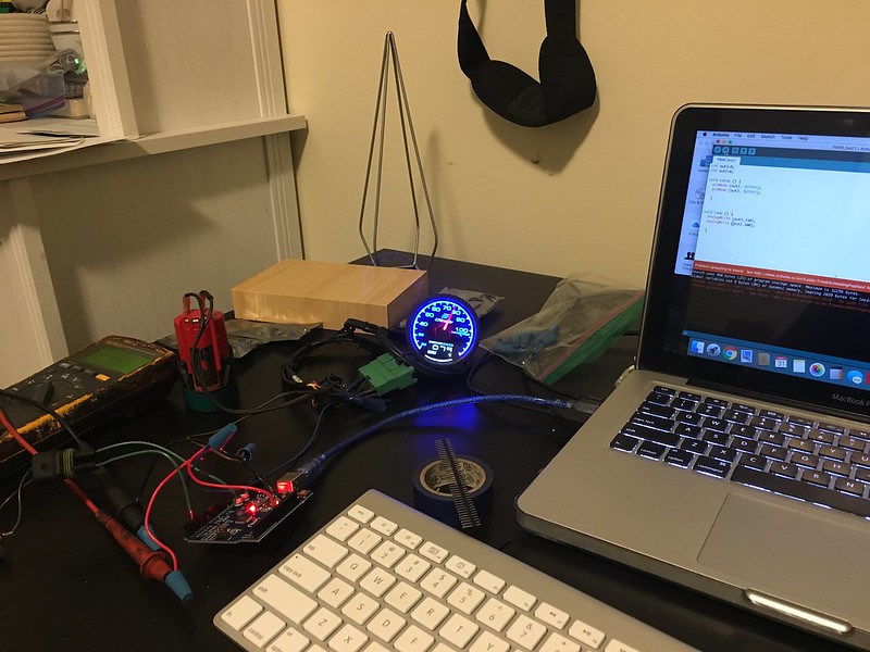
playing with the PWM output I can get the gauge to change, but it won’t hold a steady state. I believe I’ll need a Digital to Analogue converter to steady it out.
I’ll also need help from a buddy with getting the code right, I can copy and paste a working string here and there but I’m pretty in over my head otherwise lol.
moving on, modified my now useless radiator brace bar to fit the intercooler.
so I can get back to my struggle of V mount to 7 mount or somewhere in between
getting this stuff to sit right took some creativity as I only have 2 hands

V mount just looks so cool from the front…
12-01-19, 11:54 PM
#259
Senior Member
Thread Starter
7 mount allows for room up front to play with…
RIP angle grinder. One of my most used tools gave up the magic smoke. I’ll send it out for repair but I won’t see it until next year easily

Since I had decided to move my whole engine/trans back the shifter doesn’t fit anymore. Some research showed me it was pretty easy to modify the t2 shifter but more googling showed me that the NA miata 1.6 trans, FB and FC N/A trans all have very similar shifter turrets and assemblies. So obviously I had trouble finding someone who would sell me just that 2 pieces I needed. Buddy in the Rx7 group chat I’m in gave me a number for a guy with a trans and he was willing to buy the trans off after for the gear set. Its apparently an upgrade for FB’s.
He also gave me a FB shifter turret to see if that fit, and while it didn’t it allowed me to get a photo I hadn’t been able to find anywhere of all 3 together.
From left to right: T2 - FB - Miata

paired with the right length shifter rod, theres no messing around cutting and welding. All oem parts too

Swapping the shifter rod is pretty quick and easy too. Worst part is waiting for the gasket maker to dry

shifter lineup is perfect, bang on stock

some china bits started to roll in, these are M14 to -6 for the turbo water lines. They need a little bit of attention for burs etc but cheeeaaapp even compared to Performance world (and I’m fairly certain they are the same)

very excited to try these out too. Theres 2 types of these Van Jen on ali, this style has been sold under a few names randomly and they cost a bit more then the other style which is a hypertune knock off but the hypertune style have a bolt that secures them vs a pin. I don’t really like the cotter pin, but I’ll figure out a different solution later. They seal really tight, but with a bit of oil on the O rings they wiggle a bit too like they are supposed to. got 2 3” and 1 2.5”. I want to make both sides of the intercooler use these and the throttle body.
12-01-19, 11:55 PM
#260
Senior Member
Thread Starter

got a big box full of bends, pipes and silicone couplers for all the intake and intercooler to turbo etc piping. If I measured right I hopefully won’t have to order more
spent an evening practicing crimps and connectors

finally test fit the adapter plate on the engine, after talking to the machinist who’s helping me with the flywheel adapter he’s a little uncomfortable with the lack of contact the bolt heads make

put the bolts in and used some paint to see how much contact its actually making and well… its not a lot. We had made the holes a bit bigger in order to accommodate if our bolt holes weren’t perfect but we went a little too big. After considering my options I think I’m going to get the plate recut. Which isn’t cheap but worth it if it means I get to keep my legs later. First I’m going to get the transmission side dowels in there to ensure that fitment between the 2 is perfect or close enough to it that I won’t have trans issues later. I understand with a bellhouse run out test I should see under 0.015” runout
set up a test rig to try the Cam sensor out, hoping I don’t have to cut part of the cam distributor drive off to get a useable pattern. I have a log but I’m not yet sure if the Black supports custom cam profiles anymore as with the latest software update its not a option. If I cut the tooth it becomes a 1 tooth signal and thats a useable profile so thats the worst case scenario. But I don’t want to do that every time I swap engines
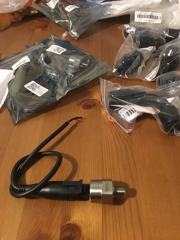
got some “honeywell style” sensors from china. I’m going to run these and similar temp senders for most inputs. I’m not into risking it for the MAP, Knock, and 02. Most other senders either work or they don’t, and the ECU will catch off set scale readings. I plan to be checking logs pretty routinely.

removed the front subframe, pressured washed and cleaned the whole thing and the engine bay. Very tired of getting grime and dirt on my face and hands overtime I look at it the wrong way.

The power steering lines on the rack were pretty mangled from going through the grannies cradle for the 5.0 swap so I pulled lines off a spare rack and it turns out S4 and S5 are a little different.
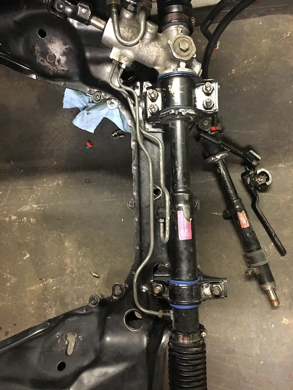
bit of tweaking and its fine
After 4 tries I got the right belt for my lathe, apparently not generic tooth and length

I was trying to grind my own HSS tools, but youtube videos are just not enough direction for me I guess lol. Bought a bit holder and bit from a local tool place, which I later found is directly from China… but it cuts so much better/faster
12-01-19, 11:56 PM
#261
Senior Member
Thread Starter

these are cut from the old HSS bits,
This one is from the carbide cutter. The other thing is a press die I made

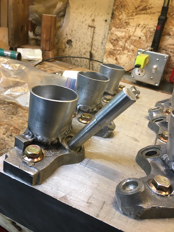
Bought tube that just slipped over the aluminum tube I bought to do the intake runners with. The runners I used a piece of wire to determine that its about a 1.5” tube, so I got some thinner 1/16th wall or something for the runners and 1/8 wall 1.75” tube for the die. With some heat and a vise I bend it to the same shape as the intake flanges

The machined piece presses into the die ensuring its supporting the roundness of the end and the steps push the tube in while the outer step prevents it from pushing too far. A bit of oil on the whole thing just to ensure I could get it out after. And lol I couldn’t. That was an over sight, once the tube was in there it didn’t have a way out. Either direction forces it into a different shape.
Back to the drawing board
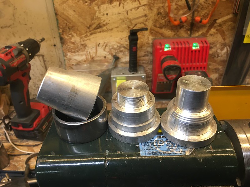
came up with this. The aluminum tube goes on the machined piece on the far right. The smallest diameter at the end is a bit smaller then the port width of the intake, I am using the vice to squeeze it. The steel ring slips over it and the 2 pieces sandwich the tube and ensure that it stays round on the round end. I crush the tube with sacrificial aluminum sheet protecting the tube from the jaws until its tight against the small diameter section. Then hammer that out and use the middle piece (which is a leftover from the first try) to get the tube out of the steel ring.
A lot of effort for something I could probably get away with just squeezing with the vice and eyeballing. Im sure even with this approach to make them more consistent I will still have to blend inside the tube where the weld will be.


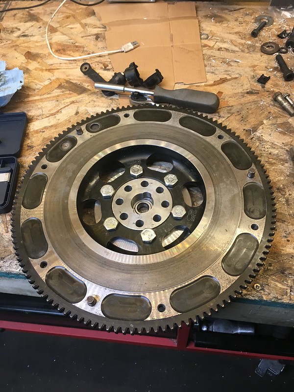
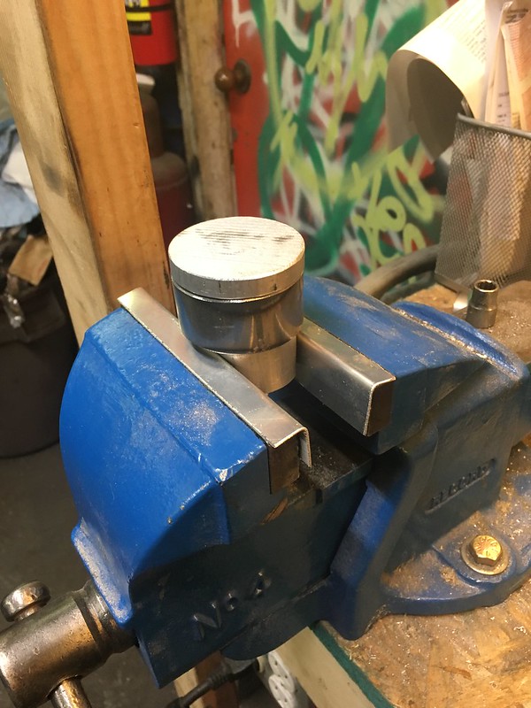
Very excited about this. Had to enlist some help for this one from a friend who works at a machine shop but man its so much better than I can do. Makes me want a CNC lather and mill lol. Still need to test fit it all with the bellhouse adapter but this is the piece that will adapt the flywheel to the crank. Its some 5440 or 4340 the shop had kicking around from a leftover piece (need to find out what he used) but the crank is rumoured to be 4340 so that or higher should be fine. The ACT flywheel alloy is listed on their site as “Chromoly” so I’m guessing its around that as well.
I owe him some whisky
Last edited by teeson; 12-02-19 at 09:12 PM.
03-23-20, 01:39 PM
#262
Senior Member
Thread Starter
Greetings everyone.
Wild time we live in right now, but since I’m stuck at home binging Netflix I will take the time to finally update this again. My wife and I just went to New Zealand for a friends wedding and got back just in time. Well in time to actually get home but not in time to avoid the 2 week basically mandatory self isolation period.

This isn’t even new, but I am just terrible lately at taking even the small amount of time required to find new music from bands I am already familiar with even. Hozier’s 2nd album Wastetland Baby; little more up beat then his 1st but really really good. He played a few songs off of it when he came to Vancouver last. I appreciate that he doesn’t seem phased by having a huge gap in between albums, as that can often ruin the process I think.
picking up where I left off
This needed a slight reduction in OD to fit the flywheel but its perfect now. Have to smack it on with a rubber mallet so I have no fears that its not centric. However I haven’t had a chance to try the whole package together yet as the bolts are a very fine thread and the ones from the engines I have are all too short. Only one place Ive been able to find bolts with the right thread and length located somewhere in california. I’m surprised I can’t find anywhere locally or even in Canada with a good range of metric bolts. Any suggestions lemme know but I’ve tried many of the go to places.
finishing up the intake flange pieces

sort of a step by step. Crush the tube until it stops, then pull it out grab the ring and smack out the machined piece.

then put the ring on the open jaws and take the other machined piece to push the now shaped tube out.
probably over kill but made for really consistent pieces. I took them real quick to the belt sander and made sure they were flat, then brought them over to SCG and got him to glue them together.


I/we were expecting it to weld terribly give that I didn’t bring him anything to test weld lol and the manifold flanges I cut down and made flat were cast and the tubes were thin. But turned out pretty decent. Heat sink block was a nice touch i thought.

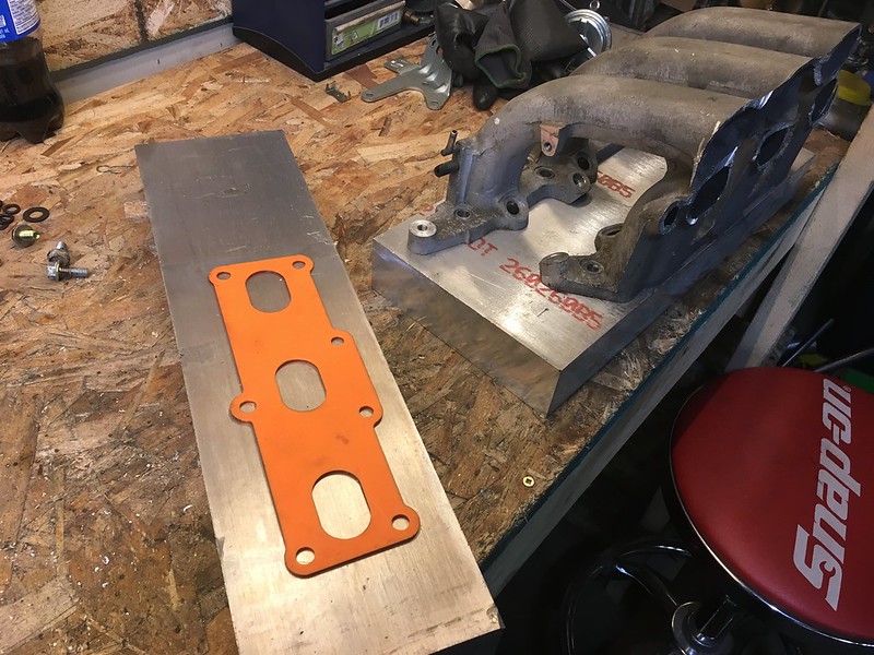
Next issue I knew I was going to run into was fitting the injectors and rail in the tight little space I have to work with.


Tried flipping them every which way and this was the most room I can squeeze. I don’t like that they don’t sit like equal, horizontally I mean. Thankfully they are under the intake manifold so I won’t see them. One day when I buy a mill I’ll buy some fuel rail stock (or a RB rail cut in 1/2) and make a better one.
since I don’t have a mill and frankly even if I did I’m not too sure how to set this part up anyway, I need to counterbore a hole for the O rings to seat the bottom of the injector. The injectors I got a deal on are from an RB and use an outdated O ring that the injector sits on instead of it going around the bottom and the injector sitting directly on the manifold. Hope that makes sense.
lathed a piece that would hopefully allow me to set up a drill press or mill with some accuracy as to the location and angle the hole sits at. Finding hole centre isn’t the hard part here, I’m guessing theres a tool out there somewhere that does this but I’m sure its $$.
So thats where that is at for now, I don’t have a drill press and haven’t bought one yet.

Wild time we live in right now, but since I’m stuck at home binging Netflix I will take the time to finally update this again. My wife and I just went to New Zealand for a friends wedding and got back just in time. Well in time to actually get home but not in time to avoid the 2 week basically mandatory self isolation period.
This isn’t even new, but I am just terrible lately at taking even the small amount of time required to find new music from bands I am already familiar with even. Hozier’s 2nd album Wastetland Baby; little more up beat then his 1st but really really good. He played a few songs off of it when he came to Vancouver last. I appreciate that he doesn’t seem phased by having a huge gap in between albums, as that can often ruin the process I think.
picking up where I left off
This needed a slight reduction in OD to fit the flywheel but its perfect now. Have to smack it on with a rubber mallet so I have no fears that its not centric. However I haven’t had a chance to try the whole package together yet as the bolts are a very fine thread and the ones from the engines I have are all too short. Only one place Ive been able to find bolts with the right thread and length located somewhere in california. I’m surprised I can’t find anywhere locally or even in Canada with a good range of metric bolts. Any suggestions lemme know but I’ve tried many of the go to places.
finishing up the intake flange pieces
sort of a step by step. Crush the tube until it stops, then pull it out grab the ring and smack out the machined piece.
then put the ring on the open jaws and take the other machined piece to push the now shaped tube out.
probably over kill but made for really consistent pieces. I took them real quick to the belt sander and made sure they were flat, then brought them over to SCG and got him to glue them together.
I/we were expecting it to weld terribly give that I didn’t bring him anything to test weld lol and the manifold flanges I cut down and made flat were cast and the tubes were thin. But turned out pretty decent. Heat sink block was a nice touch i thought.
Next issue I knew I was going to run into was fitting the injectors and rail in the tight little space I have to work with.
Tried flipping them every which way and this was the most room I can squeeze. I don’t like that they don’t sit like equal, horizontally I mean. Thankfully they are under the intake manifold so I won’t see them. One day when I buy a mill I’ll buy some fuel rail stock (or a RB rail cut in 1/2) and make a better one.
since I don’t have a mill and frankly even if I did I’m not too sure how to set this part up anyway, I need to counterbore a hole for the O rings to seat the bottom of the injector. The injectors I got a deal on are from an RB and use an outdated O ring that the injector sits on instead of it going around the bottom and the injector sitting directly on the manifold. Hope that makes sense.
lathed a piece that would hopefully allow me to set up a drill press or mill with some accuracy as to the location and angle the hole sits at. Finding hole centre isn’t the hard part here, I’m guessing theres a tool out there somewhere that does this but I’m sure its $$.
So thats where that is at for now, I don’t have a drill press and haven’t bought one yet.
03-23-20, 01:39 PM
#263
Senior Member
Thread Starter
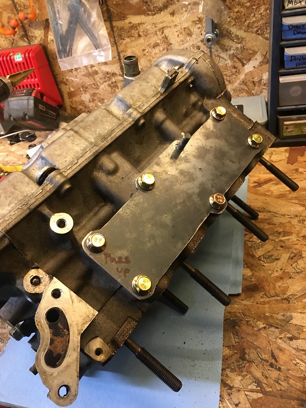
Since I’ve decided against using the distributor at all I made a plug for it. I will later drill this out and put the ford sensor in it

I’ll be adding a plate that attaches it to the head just to prevent it coming out and keep the sensors air gap consistent, but thats a later thing.
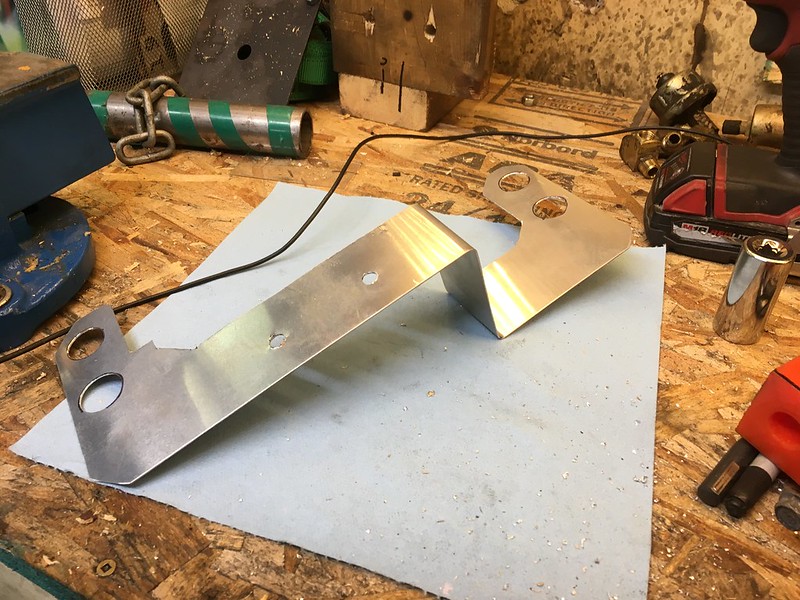
made a bracket for the DBW pedal. Thankfully pretty simple
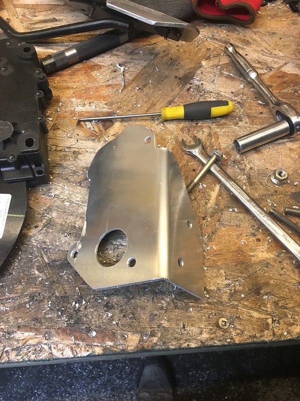

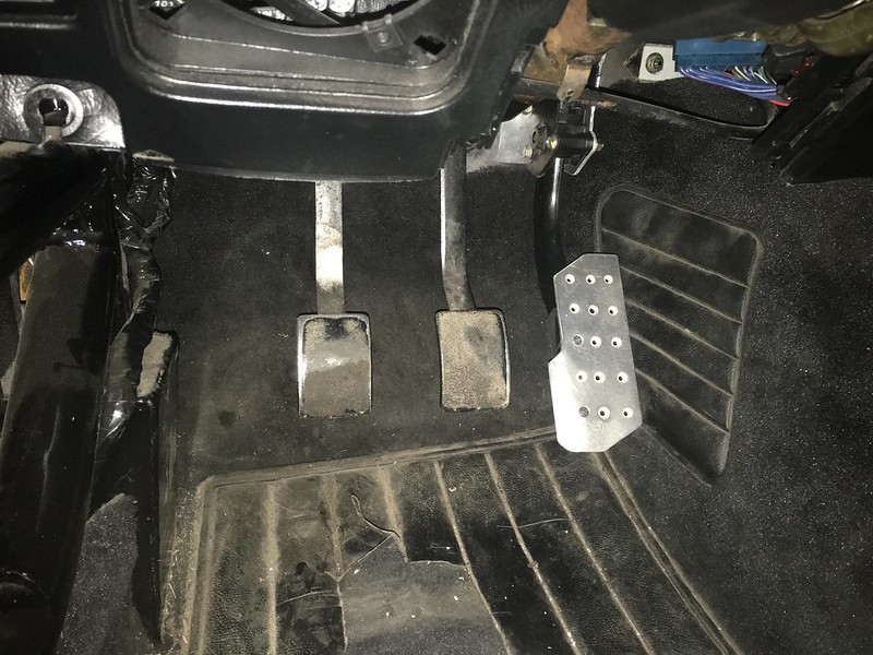
theres about 5 minutes of mods to the pedal and only really to the plastic bit at the end. So replacing it should I ever have to is simple. I am also pleased this pedal is off the same vehicle as the TB, not that it matters at all lol.

Got a pair of these, going to mount one on each turbo to simply vacuum lines. I chose aesthetics over cost and possibly reliability. Don’t know what happens if one fails and one turbo is over boosting the other but hopefully EGT’s or AFR’s or something will give me a sign in that rare event.

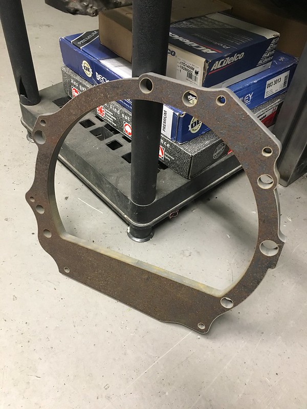
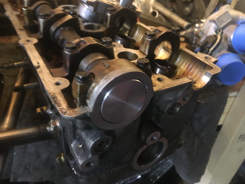
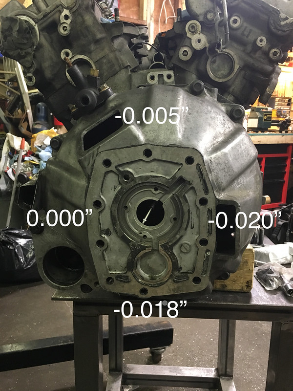
This was a milestone event. The hardware I got fit, the bellhouse fits, the engine fits. The same machinist tapped some holes in for me and machined a dowel (i ruined one getting it out of the 13B iron) so it could all be bolted together. This was also the 2nd to last moment of truth as I was going to measure the centre to centre run out and see if any changes needed to be made.

It probably took me over an hour to get this setup correctly

had to get the arm to sit just right, remove anything in the way, get the dial sitting just right so that I could see it as it spun around. In all the videos and research I did the hole in the bellhouse was always bigger then this. I was also advised after that I could have used a lever dial indicator (which I don’t have anyway) instead. The base is usually mounted on the flywheel as well but I don’t have bolts to do that either soooo here we are. I was way to nervous/excited/impatient to not do this asap.


I’ll be adding a plate that attaches it to the head just to prevent it coming out and keep the sensors air gap consistent, but thats a later thing.
made a bracket for the DBW pedal. Thankfully pretty simple
theres about 5 minutes of mods to the pedal and only really to the plastic bit at the end. So replacing it should I ever have to is simple. I am also pleased this pedal is off the same vehicle as the TB, not that it matters at all lol.
Got a pair of these, going to mount one on each turbo to simply vacuum lines. I chose aesthetics over cost and possibly reliability. Don’t know what happens if one fails and one turbo is over boosting the other but hopefully EGT’s or AFR’s or something will give me a sign in that rare event.
This was a milestone event. The hardware I got fit, the bellhouse fits, the engine fits. The same machinist tapped some holes in for me and machined a dowel (i ruined one getting it out of the 13B iron) so it could all be bolted together. This was also the 2nd to last moment of truth as I was going to measure the centre to centre run out and see if any changes needed to be made.
It probably took me over an hour to get this setup correctly
had to get the arm to sit just right, remove anything in the way, get the dial sitting just right so that I could see it as it spun around. In all the videos and research I did the hole in the bellhouse was always bigger then this. I was also advised after that I could have used a lever dial indicator (which I don’t have anyway) instead. The base is usually mounted on the flywheel as well but I don’t have bolts to do that either soooo here we are. I was way to nervous/excited/impatient to not do this asap.
03-23-20, 01:40 PM
#264
Senior Member
Thread Starter
did the test at least 4 different times, and actually remembered to write down results twice. I would take the bellhouse off and put it back on again to simulate removing the trans in an effort to see if the results changed.

from all the research I did the most allowable runout seems to be .030”
If you know otherwise please share, I have yet to try it on an hem bell housing to a normal oem to see how much out they are due to manufacturing inconsistencies if there are any.

starter fits


adaptor matches the curves and blends it all together quite nice. I don’t think I will be making any changes to the design aside from the hole size and probably tapping a few holes instead of passing them through on for the engine blocks side.

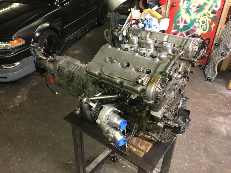
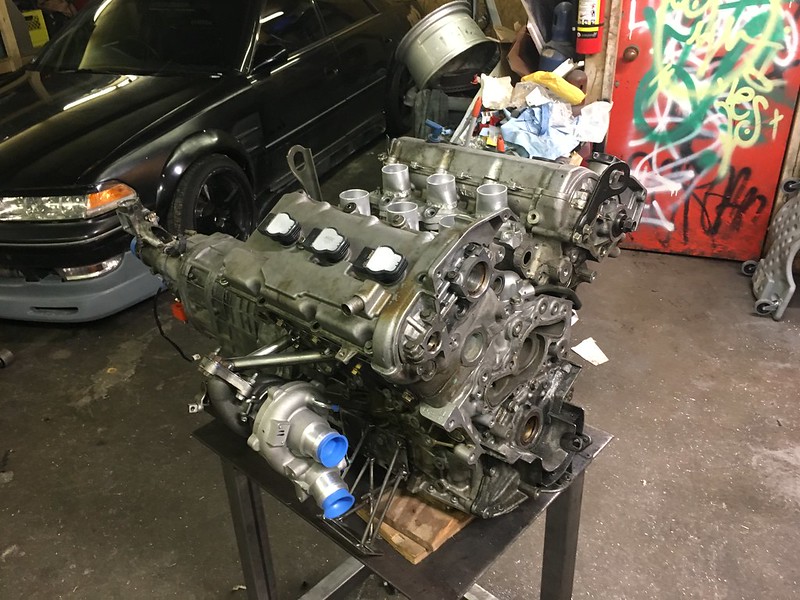
Here is the engine so far as a package. I am quite pleased with this so far.

here we are using some CAD to get an idea for the intake
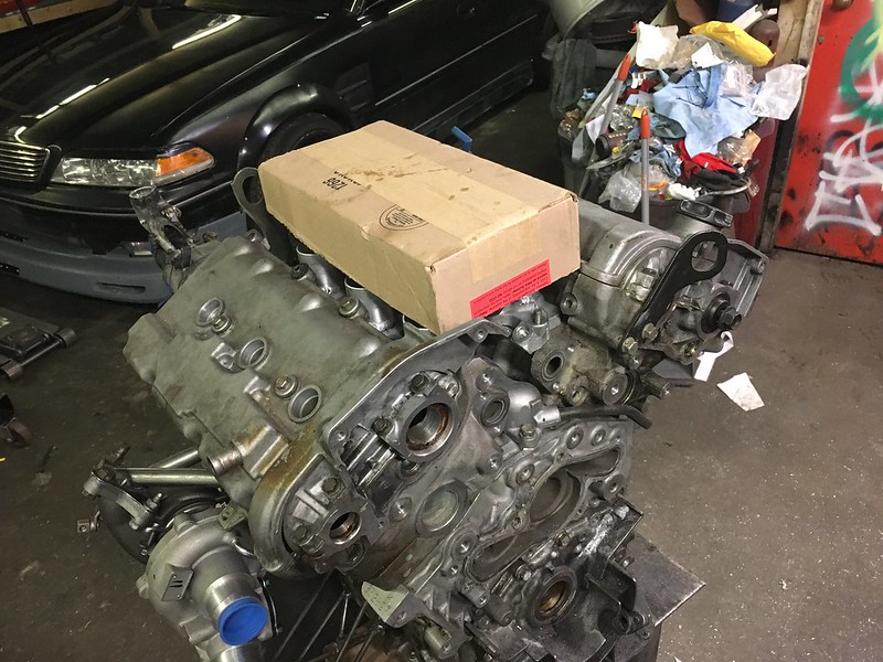


really like having those plastic covers lol, feels professional. Ideally want to one day put everything on it and then drop it in.
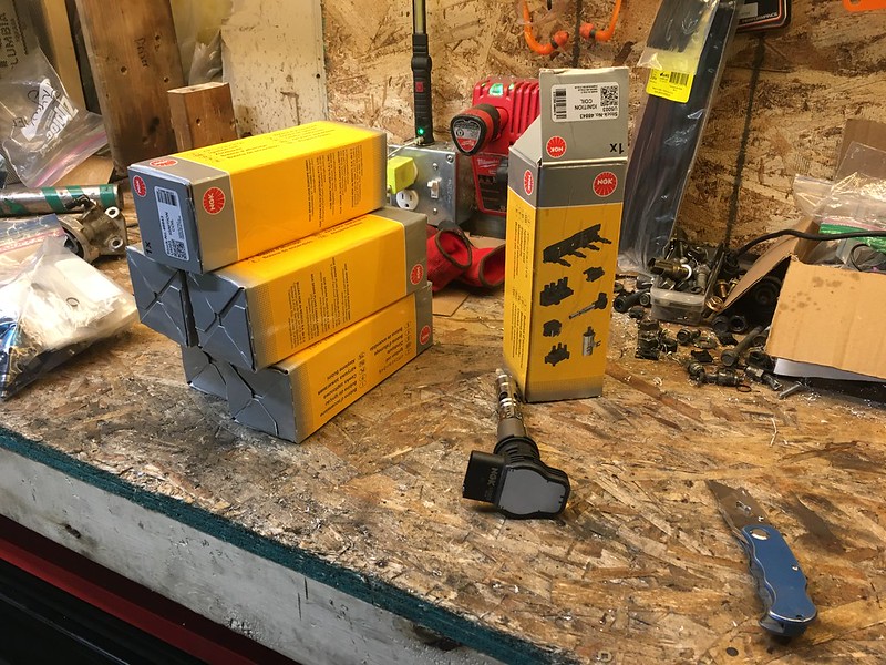
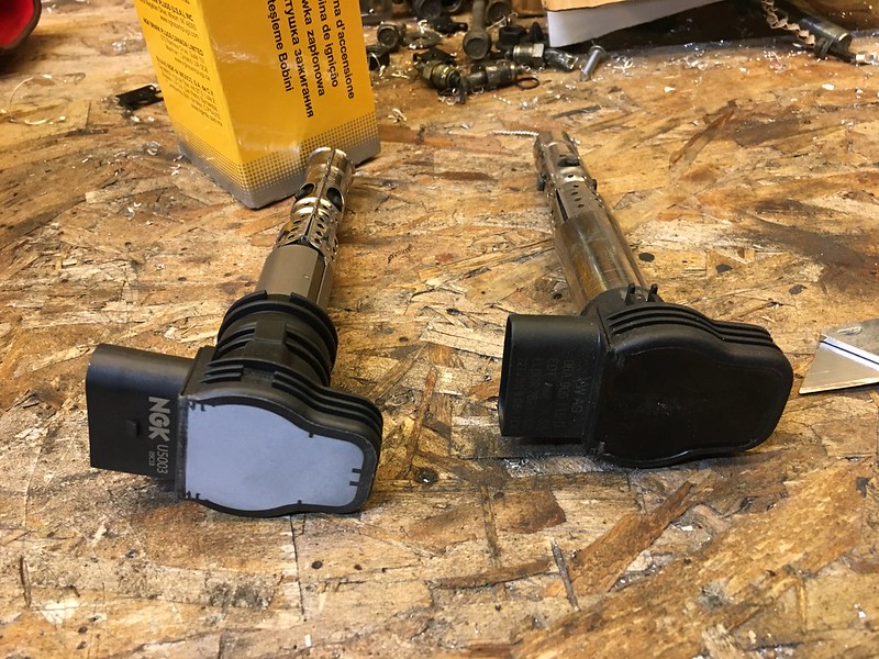
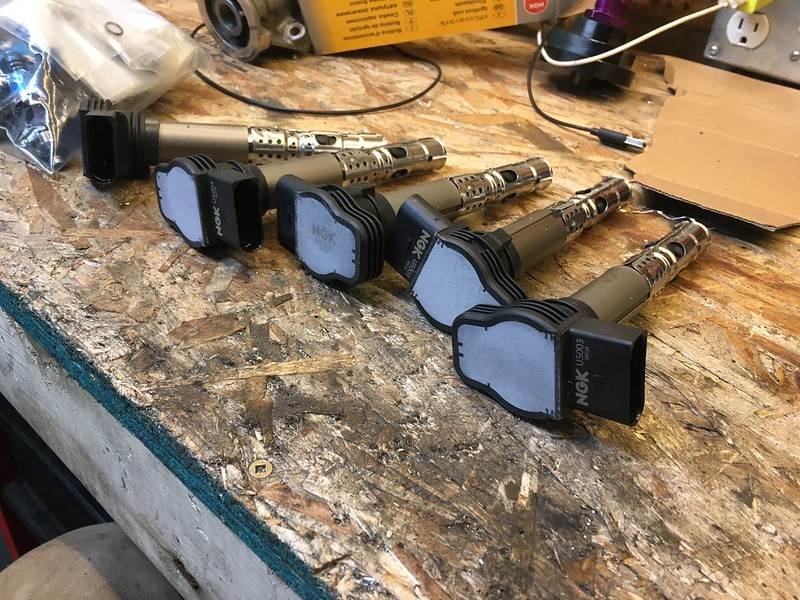
got a large order from Rockauto including these which are not what I thought. not sure why these are different then the picture, looks like NGK bought them from some one else and skimmed the top with a mill or sander. 5 out of 6 have the logo on top and one has the logo on the connector. I should have bought Bosch and I probably will buy Bosch, cuz i hate how this looks.
from all the research I did the most allowable runout seems to be .030”
If you know otherwise please share, I have yet to try it on an hem bell housing to a normal oem to see how much out they are due to manufacturing inconsistencies if there are any.
starter fits
adaptor matches the curves and blends it all together quite nice. I don’t think I will be making any changes to the design aside from the hole size and probably tapping a few holes instead of passing them through on for the engine blocks side.
Here is the engine so far as a package. I am quite pleased with this so far.
here we are using some CAD to get an idea for the intake
really like having those plastic covers lol, feels professional. Ideally want to one day put everything on it and then drop it in.
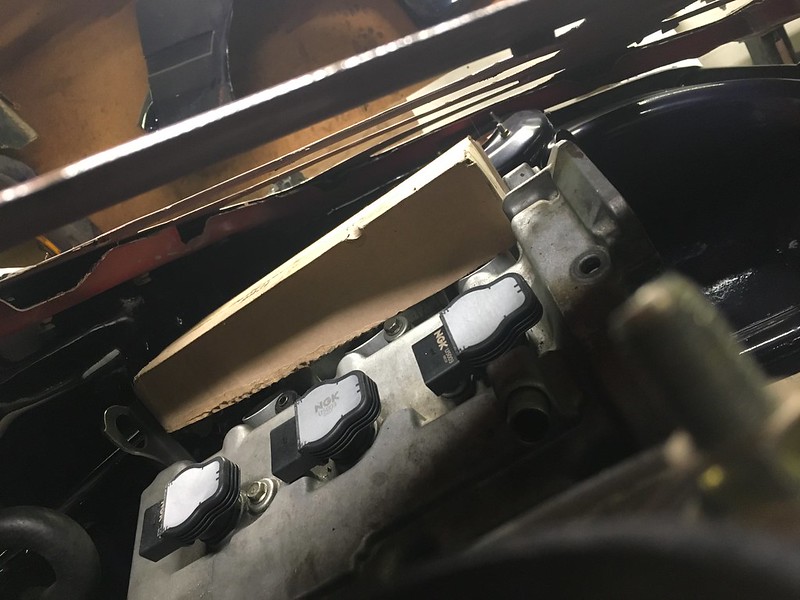
got a large order from Rockauto including these which are not what I thought. not sure why these are different then the picture, looks like NGK bought them from some one else and skimmed the top with a mill or sander. 5 out of 6 have the logo on top and one has the logo on the connector. I should have bought Bosch and I probably will buy Bosch, cuz i hate how this looks.
03-23-20, 01:41 PM
#265
Senior Member
Thread Starter

but anyway


got a sick deal from a local rx7 guy on a turbosmart FPR with a sensor.

took it apart and checked the diaphragm and gave it a clean
was debating on buying a rep aeromotive from china and put a aeromotive diaphragm in it. this ended up being the same price and sits better with me. Aeromotive do not manufacture in china and have made great effort to prevent their products being ripped off and they make good stuff to begin with, so I’m gonna respect that and not buy a rep. or theirs LOL.
a weird philosophy I know…

the fitment hood makes an appearance

looks like it will be really close if I don’t want to cut webbing near the TB part of the intake manifold

my mom got me and my dad a neat christmas gift. Maybe one day this will be an actual thing but for now its a great running joke between me, my friends and my dad.
03-23-20, 01:42 PM
#266
Senior Member
Thread Starter
next issue to solve
where to put the remote oil filter block

option 1: this is how I had always pictured it, but it doesn’t fit really. The sway bar hits the filter, if it move it towards the rad the fitting ends up in the fan. If i move it up the fittings do the same thing and filter becomes harder to take off due to it sitting above the sway bar.

option 2: now this solves many of those, doesn’t look as cool as I pictured but it fits. And draining the filter would be less messy. Can also get at the T stat plug in it. I also really didn’t want to put it on a funky angle or anything.
so with a solution there I can go ahead with final radiator location


got real fancy with a laser level to help insure that the rad is sitting level and square and at the height I want it at.
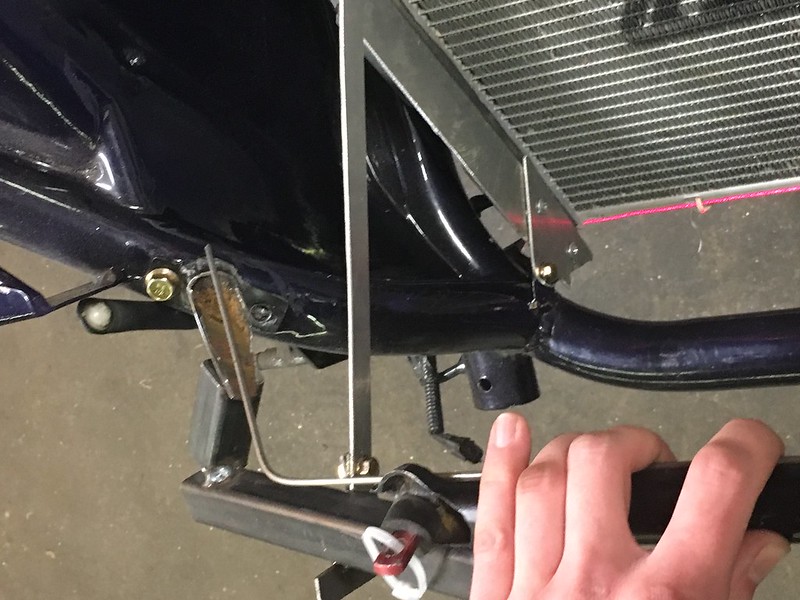
some quick tabs welded on to make an upper location

bent a tab to get a profile for the intercooler to sit at. I will bend a sheet the entire length of the rad that will hold the intercooler up and some foam to seal it
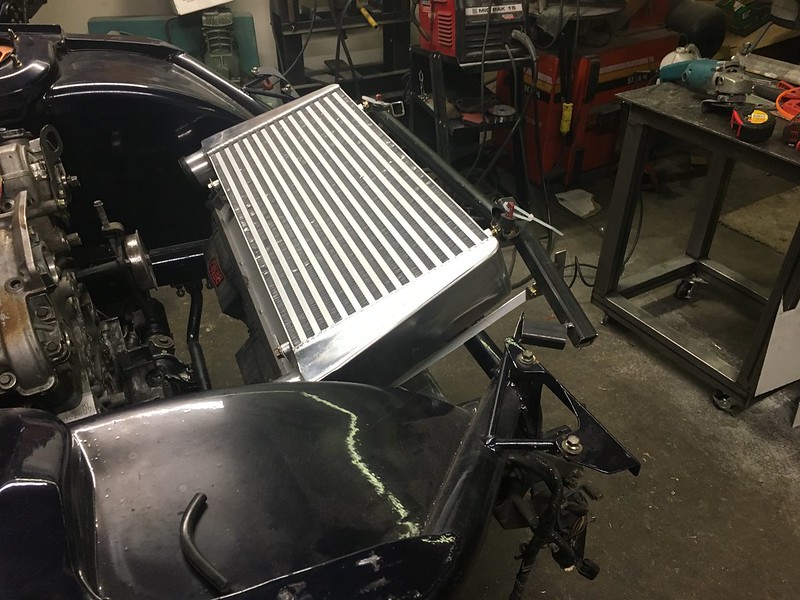
this is sitting how its going to be I think

had to factor hood clearance in there

then back to the oil filter
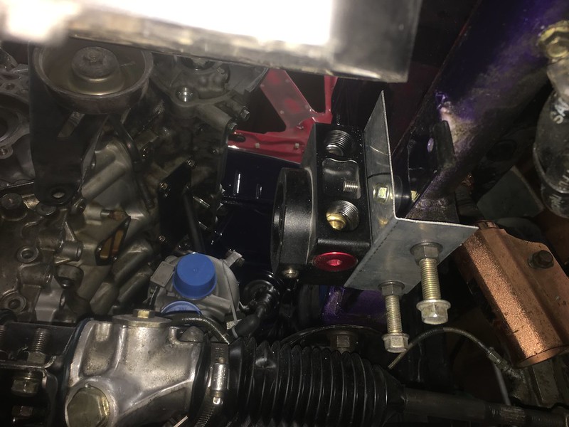
I didn’t like how flexy it was without any triangulation. So I figured to use the sway bar mount and the plate I had welded on originally (one bolt anyway). Need to remake it thicker material, I like making stuff first out of thin and easy to cut all sheet. Bends easy, un bends easy, can cut it with tin snips if need be.
where to put the remote oil filter block
option 1: this is how I had always pictured it, but it doesn’t fit really. The sway bar hits the filter, if it move it towards the rad the fitting ends up in the fan. If i move it up the fittings do the same thing and filter becomes harder to take off due to it sitting above the sway bar.
option 2: now this solves many of those, doesn’t look as cool as I pictured but it fits. And draining the filter would be less messy. Can also get at the T stat plug in it. I also really didn’t want to put it on a funky angle or anything.
so with a solution there I can go ahead with final radiator location
got real fancy with a laser level to help insure that the rad is sitting level and square and at the height I want it at.
some quick tabs welded on to make an upper location
bent a tab to get a profile for the intercooler to sit at. I will bend a sheet the entire length of the rad that will hold the intercooler up and some foam to seal it
this is sitting how its going to be I think
had to factor hood clearance in there
then back to the oil filter
I didn’t like how flexy it was without any triangulation. So I figured to use the sway bar mount and the plate I had welded on originally (one bolt anyway). Need to remake it thicker material, I like making stuff first out of thin and easy to cut all sheet. Bends easy, un bends easy, can cut it with tin snips if need be.
03-23-20, 01:42 PM
#267
Senior Member
Thread Starter
Since I’m building everything why not keep going right?


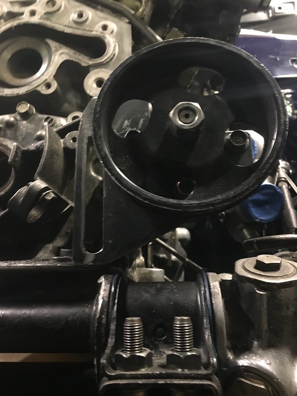
the power steering pump is on the back/passenger side factory, this doesn’t work for me. The rack connections are on the drivers side, and if the alt swapped places with it then its closer to where the connections are as well. I also didn’t like how high the factory brackets put them, it interfered with where the turbo piping will fit. I experimented if the turbos sat lower or flipped over and everything has compromise. I deemed this to be the way I want it so thats how I’m going to do it. If I find a better way I’ll probably change it. Theres no rule book here, as they keep saying at drift works during the E46 V10 restoration youtube series “we’re just having a go”
As usual flimsy thin sheet to give a good idea of what I’m after. Holding it in place with my hand just doesn’t do it for me lol. I also struggled here to find a way to make sure the belt is aligned. The other part that sucks is the belt rib counts are switch from P/S to alt. Mazda put the water pump and power steering on the same belt, which I think is silly. I deem the alt more important than power steering, can limp it home with out but can’t go very far without a water pump and alt. Perhaps they had other reasons for it, alt loads up fast or something. Ill find out I guess lol
so anyway, it fits here (very nice to have a block on the stand and one in the car to be able to mock up on both) but I have no way to tension it. But we’ll come back to this in a bit
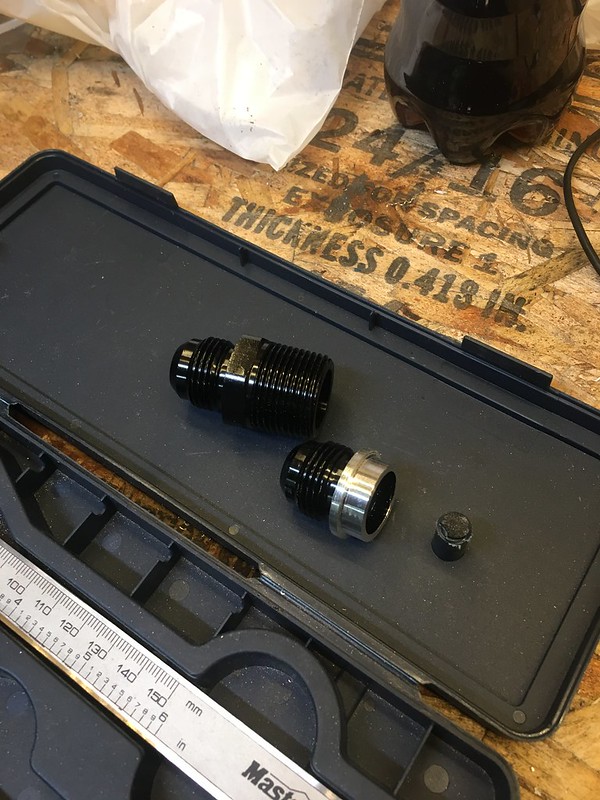
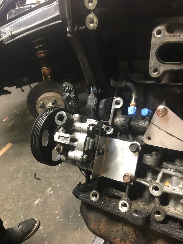
I bought these fittings that kinda ended up being useless. I didn’t want to lose any diameter in the oil system and I was trying to avoid welding aluminum so I got these which were -10AN to 3/4 NPT. They are just huge. I might use them into the oil pan but I wont have room anywhere else. That idea comes from Al from Skid Factory, he doesn’t like weld on AN fittings as the surface of the taper is what seals the fitting. Any damage it takes during removal or assembly can ruin it and then its welded to the part and a big job to fix. you’re less likely to ruin inner threads.
So I took the threaded part off with the lathe and made it a weld on fitting essentially. I picked a size I could actually get a drill bit for (important forethought) and cut it down to 7/8”
then I set about making a block for it out of a large chunk leftover from the exhaust manifold heat sink/weld block
need a drill press right about now. even better a mill.

the issue here is as usual space. The probable location for piping was going to put it all up in this oil adapters face. So i was like “oi ill just start with a thick block and machine it with an angle grinder and belt sander until the fittings can go in at angle and problem solved”
after many wasted hours that didn’t work. I need a 5 axis CNC mill to achieve what I was after lol. Made a mistake grinding and tossed it.
I never exactly liked how close the turbos waste gate sat to the steering shaft. After messing around with the turbo position I found a different place for it to sit that may make my manifold slightly harder to build but keeps it a bit further away while suiting downpipes and everything else clearance. Thats exactly why I like building everything with mock locations and mock brackets until everything fits. So many variables here its hard at times to make choices. I even mocked up a single turbo location and decided that it would have comprises just the same as twins

everything is a compromise

the power steering pump is on the back/passenger side factory, this doesn’t work for me. The rack connections are on the drivers side, and if the alt swapped places with it then its closer to where the connections are as well. I also didn’t like how high the factory brackets put them, it interfered with where the turbo piping will fit. I experimented if the turbos sat lower or flipped over and everything has compromise. I deemed this to be the way I want it so thats how I’m going to do it. If I find a better way I’ll probably change it. Theres no rule book here, as they keep saying at drift works during the E46 V10 restoration youtube series “we’re just having a go”
As usual flimsy thin sheet to give a good idea of what I’m after. Holding it in place with my hand just doesn’t do it for me lol. I also struggled here to find a way to make sure the belt is aligned. The other part that sucks is the belt rib counts are switch from P/S to alt. Mazda put the water pump and power steering on the same belt, which I think is silly. I deem the alt more important than power steering, can limp it home with out but can’t go very far without a water pump and alt. Perhaps they had other reasons for it, alt loads up fast or something. Ill find out I guess lol
so anyway, it fits here (very nice to have a block on the stand and one in the car to be able to mock up on both) but I have no way to tension it. But we’ll come back to this in a bit
I bought these fittings that kinda ended up being useless. I didn’t want to lose any diameter in the oil system and I was trying to avoid welding aluminum so I got these which were -10AN to 3/4 NPT. They are just huge. I might use them into the oil pan but I wont have room anywhere else. That idea comes from Al from Skid Factory, he doesn’t like weld on AN fittings as the surface of the taper is what seals the fitting. Any damage it takes during removal or assembly can ruin it and then its welded to the part and a big job to fix. you’re less likely to ruin inner threads.
So I took the threaded part off with the lathe and made it a weld on fitting essentially. I picked a size I could actually get a drill bit for (important forethought) and cut it down to 7/8”
then I set about making a block for it out of a large chunk leftover from the exhaust manifold heat sink/weld block
need a drill press right about now. even better a mill.
the issue here is as usual space. The probable location for piping was going to put it all up in this oil adapters face. So i was like “oi ill just start with a thick block and machine it with an angle grinder and belt sander until the fittings can go in at angle and problem solved”
after many wasted hours that didn’t work. I need a 5 axis CNC mill to achieve what I was after lol. Made a mistake grinding and tossed it.
I never exactly liked how close the turbos waste gate sat to the steering shaft. After messing around with the turbo position I found a different place for it to sit that may make my manifold slightly harder to build but keeps it a bit further away while suiting downpipes and everything else clearance. Thats exactly why I like building everything with mock locations and mock brackets until everything fits. So many variables here its hard at times to make choices. I even mocked up a single turbo location and decided that it would have comprises just the same as twins
everything is a compromise
03-23-20, 01:43 PM
#268
Senior Member
Thread Starter
so to plan B. 1/2 Alu plate which came out looking much nicer with the same tools on hand. Transfer punches are key here
put it all together aaaaaand
It looks like ill be needing to do 45* couplers coming off the turbo inlets anyway so i ordered 2 more. Just need to weld it up, may or may not use my adapters. I ordered -6 weld on along with 45* -10AN fittings
now the keen eyed will notice thats not the same bracket holding the power steering pump on, one more story before getting back to that

after much googling I found a company that sells these “mini” alternators. They are actually for a mercury outboard motor but are smaller then the stock KL alt and only give up 10amps peak. not sure what rpm the stock alt gives its 90 amps at but I might be able to play with pulley size here and make this one work. They are also super cheap compared to a KL one and next day amazon prime eligible. They also make a hotter wind version in the same frame size as a more expensive option should I find that I’m maxing the output.

I don’t feel this does the size difference justice, it doesn’t look like much but it kinda is.
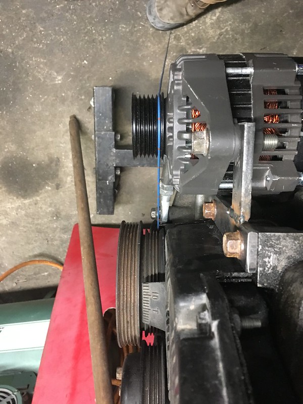
same issue finding a way to align the ribs

this is so much easier then the power steering pump, and does anyone know a proper name for those tubes that are threaded on both ends but opposite threads? I can buy them from summit and Jegs and whatever else but they all seem to have different names.

trying to use whatever I had around the garage and then I had a brain wave
I love these “aha” moments
In this case I can measure off the bar to the rib with a caliber and make sure its bang on


put it all together aaaaaand
It looks like ill be needing to do 45* couplers coming off the turbo inlets anyway so i ordered 2 more. Just need to weld it up, may or may not use my adapters. I ordered -6 weld on along with 45* -10AN fittings
now the keen eyed will notice thats not the same bracket holding the power steering pump on, one more story before getting back to that
after much googling I found a company that sells these “mini” alternators. They are actually for a mercury outboard motor but are smaller then the stock KL alt and only give up 10amps peak. not sure what rpm the stock alt gives its 90 amps at but I might be able to play with pulley size here and make this one work. They are also super cheap compared to a KL one and next day amazon prime eligible. They also make a hotter wind version in the same frame size as a more expensive option should I find that I’m maxing the output.
I don’t feel this does the size difference justice, it doesn’t look like much but it kinda is.
same issue finding a way to align the ribs
this is so much easier then the power steering pump, and does anyone know a proper name for those tubes that are threaded on both ends but opposite threads? I can buy them from summit and Jegs and whatever else but they all seem to have different names.
trying to use whatever I had around the garage and then I had a brain wave
I love these “aha” moments
In this case I can measure off the bar to the rib with a caliber and make sure its bang on
03-23-20, 01:46 PM
#269
Senior Member
Thread Starter
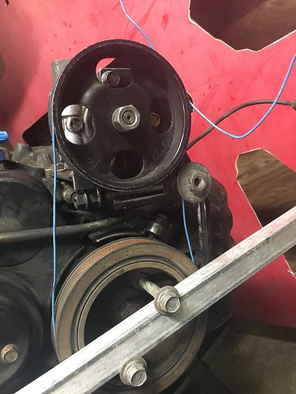
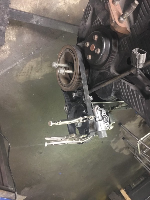
it fits in the car, pretty close to the oil pump and steering rack

just to prove to myself i didn’t waste $60 i tossed the stock alt in to see how it sat, kinda tight. It just can’t get as close to the block which make it seem even bigger

tried the same mounting location aaannd pretty similar but kept the original


theres just going to be a lot going on piping wise….
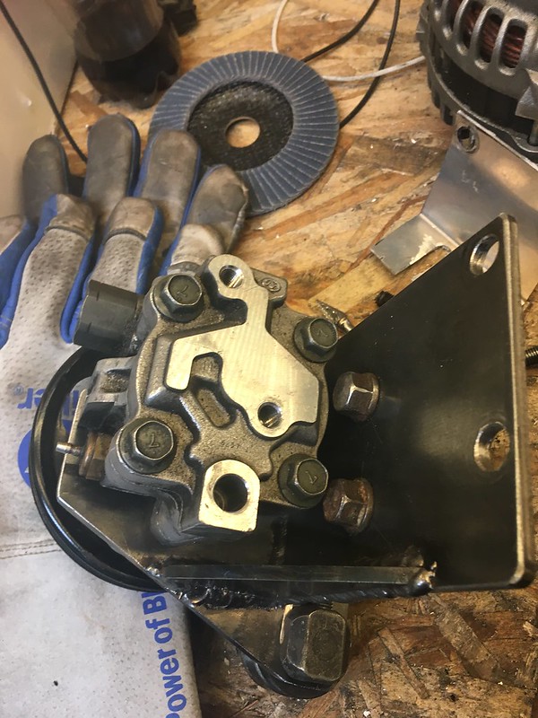
so finally back to the power steering pump
bar makes it super easy to clamp and be 100% in alignment with the pulley. The alt has the advantage of bolting to a machined surface which is parallel with the crank pulley. The pump’s bracket will be welded so its important that I can keep it square
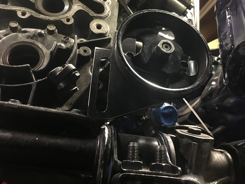
so using the same idea as the stock tensioner, a bolt that slides a pulley up and down, I made a tight fitting solution.

ended up hitting so I cut it and later remade the front of the bracket, I was happier with how the 2nd one came out cosmetically too

just to prove to myself i didn’t waste $60 i tossed the stock alt in to see how it sat, kinda tight. It just can’t get as close to the block which make it seem even bigger
tried the same mounting location aaannd pretty similar but kept the original
theres just going to be a lot going on piping wise….
so finally back to the power steering pump
bar makes it super easy to clamp and be 100% in alignment with the pulley. The alt has the advantage of bolting to a machined surface which is parallel with the crank pulley. The pump’s bracket will be welded so its important that I can keep it square
so using the same idea as the stock tensioner, a bolt that slides a pulley up and down, I made a tight fitting solution.
ended up hitting so I cut it and later remade the front of the bracket, I was happier with how the 2nd one came out cosmetically too
03-23-20, 01:47 PM
#270
Senior Member
Thread Starter

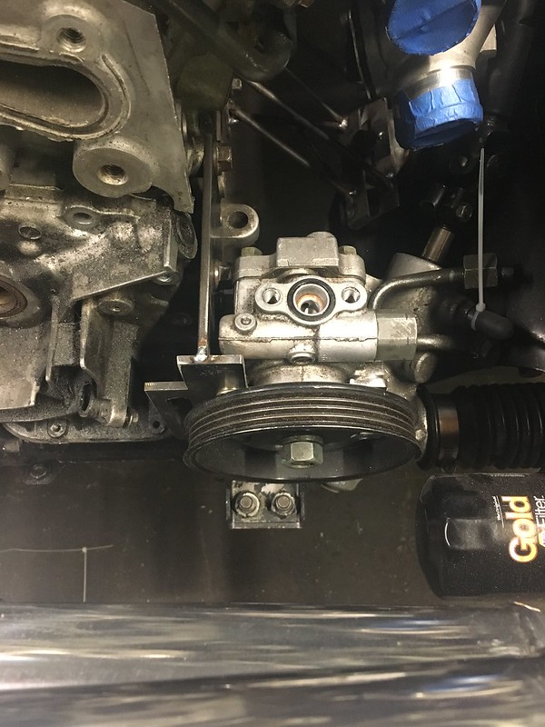
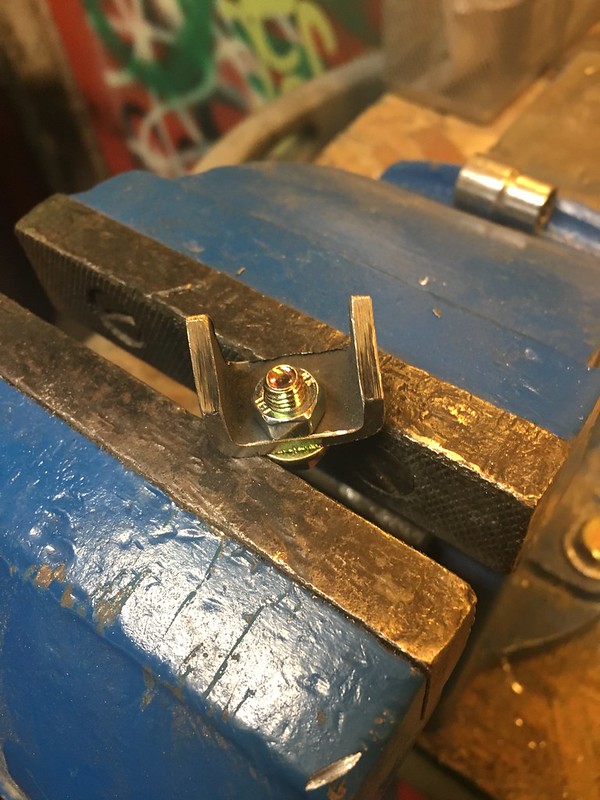
I re-used the factory tensioners bolt (cut down a bit) and the pieces that bolt the pulley to the bracket. It works the same way, spin the bolt counter clockwise and it lifts the pulley
added some triangulation, I made it out of 1/4 plate thinking it might be enough but I think this is best. maybe one day I’ll redo it in alu to save half a pound or something
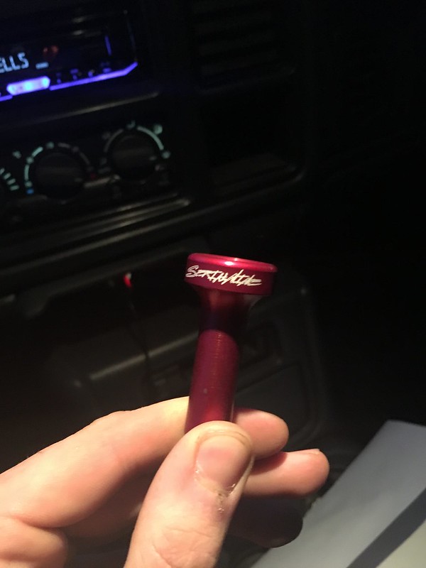
local to me company Serial Nine released new products that fit my car. Toyota and Mazda share many things and thread pitch of their e brake buttons is another

got the interior bling going/matching
(disregard the snap on shifter)
starting to get somewhere/look like something

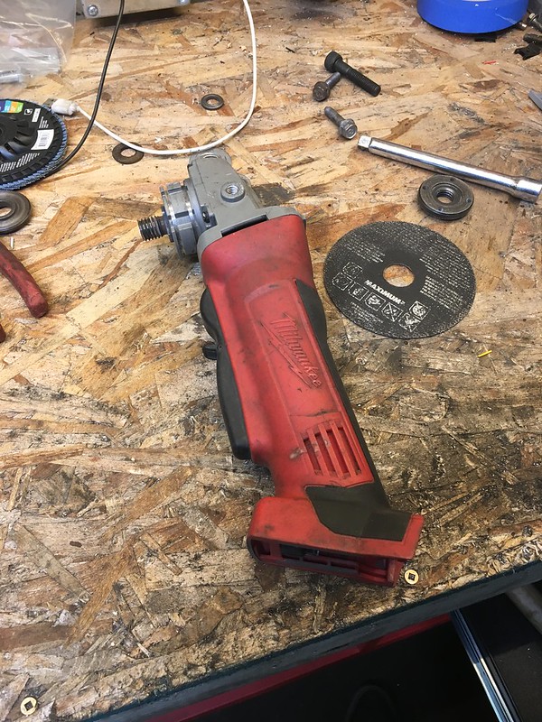
after one of the most unpleasant experiences with Milwaukee service lack of service (don’t get me started), and some of the best customer service I’ve ever received from KMS tools I now have a brushless grinder. My work has had both the brushless and brushed versions of these and I never noticed a huge difference between them. Turns out not having a wear item is worth the price difference.
not sure where to segway here, onto work or new tools.
Both I guess
Build has been progressing at a snails pace lately, hit some speed bumps that I really couldn’t have predicted how long they would take making everything fit how I wanted. I also kinda foolishly took on a fairly large side job for a friend who moved shops. That will benefit me later as he’s agreed to hour for hour labour exchange lol, and his shops tooling is mile above mine. Then poop hit the fan as they say at work and I did some crazy OT to make some deadlines. racked up a good amount of windfall and spoiled myself lol
03-23-20, 01:47 PM
#271
Senior Member
Thread Starter
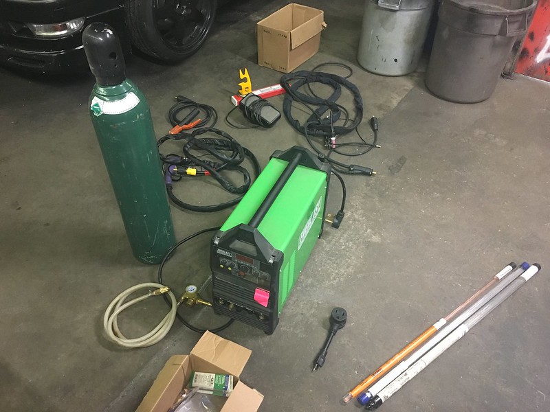
got this Everlast Tig from a friend of a friend kinda deal, he didn’t use it much and gave it to me for a good deal with all the consumables he had. Ive read good things about these everlast welders and many people who I know that are welders by trade have bought one. This is a multi process that does Tig stick and plasma cutting. I can basically guarantee i’ll never use the stick function but the plasma cutting is a new era for me

drilled some new holes and got everything to fit on the Mig’s cart. The one stop welding cart now

too bad I have no idea what I’m doing lol. I’ve tig welded maybe twice before and am not very familiar with settings or muscle memory or alloys etc. Been watching a lot of youtube and it taught me one main thing: you have to have heavy metal playing in the background or your welding video will suck

Kris is in a similar boat, though he did welding school one time and has done more tig but claims to have forgotten most of it lol. We’ve welded every scrap piece of meal kicking around and have gone through almost 2 tanks of argon already. Mig is still more comfortable with me for now but id like to get better at it. At this moment I am unsure if I’ll do all my own piping or just tack it and spend some of those hours I have banked for that side job.

still on new tools I was waiting for a need or someone to ask me about a big gauge crimper and someone finally did lol. So another sick amazon prime purchase. We actually have a very similar style one at work from Burndy that costs like $2k, so I’m very familiar with using it

purchase number 3, a printer capable of heat shrink and custom settings etc. I didn’t see a need to ball out on the top of the line Rhino. The biggest advantage I saw there was printing images off a computer. Not sure if this one does 2 lines, don’t see needing that though.

a while back I had cut up my old upper rad support bar and made a template with a piece of 1/8” rod to bend from. Neil has a 1” die so I went by and we argued about how to bend it for longer than it took to bend it (loooool)

pretty sure I missed taking pictures getting it this far but not too exciting anyway. hood pins in a much better position than last time. I want that intercooler/rad opening ducted though

cut up some 1” square tube to make 3 of these

scrap piece of aluminum to get the angle and give a flat surface for the piece to sit on so I can tack it

I forgot and can’t find the quote but something about the best and most efficient solutions solve multiple problems. So the ducting is also the mounting and the mounting is also the ducting for the radiator and intercooler. make a nice complete package that I can pull out in one piece if needed
tacked the nuts on first. did the drivers side that I had mocked up first. Then once that was tacked I took the bar off and clamped it to my welding table and used the table to insure the other 2 brackets were the same angle.
drilled some new holes and got everything to fit on the Mig’s cart. The one stop welding cart now
too bad I have no idea what I’m doing lol. I’ve tig welded maybe twice before and am not very familiar with settings or muscle memory or alloys etc. Been watching a lot of youtube and it taught me one main thing: you have to have heavy metal playing in the background or your welding video will suck
Kris is in a similar boat, though he did welding school one time and has done more tig but claims to have forgotten most of it lol. We’ve welded every scrap piece of meal kicking around and have gone through almost 2 tanks of argon already. Mig is still more comfortable with me for now but id like to get better at it. At this moment I am unsure if I’ll do all my own piping or just tack it and spend some of those hours I have banked for that side job.
still on new tools I was waiting for a need or someone to ask me about a big gauge crimper and someone finally did lol. So another sick amazon prime purchase. We actually have a very similar style one at work from Burndy that costs like $2k, so I’m very familiar with using it
purchase number 3, a printer capable of heat shrink and custom settings etc. I didn’t see a need to ball out on the top of the line Rhino. The biggest advantage I saw there was printing images off a computer. Not sure if this one does 2 lines, don’t see needing that though.
a while back I had cut up my old upper rad support bar and made a template with a piece of 1/8” rod to bend from. Neil has a 1” die so I went by and we argued about how to bend it for longer than it took to bend it (loooool)
pretty sure I missed taking pictures getting it this far but not too exciting anyway. hood pins in a much better position than last time. I want that intercooler/rad opening ducted though
cut up some 1” square tube to make 3 of these
scrap piece of aluminum to get the angle and give a flat surface for the piece to sit on so I can tack it
I forgot and can’t find the quote but something about the best and most efficient solutions solve multiple problems. So the ducting is also the mounting and the mounting is also the ducting for the radiator and intercooler. make a nice complete package that I can pull out in one piece if needed
tacked the nuts on first. did the drivers side that I had mocked up first. Then once that was tacked I took the bar off and clamped it to my welding table and used the table to insure the other 2 brackets were the same angle.
03-23-20, 01:48 PM
#272
Senior Member
Thread Starter
then final welded the whole thing other brackets included

made a goof here where I welded on the inside of the bend and it obviously shrunk and made the angle tighter. So took some heat and bent them back out to where I could just get it bolted back on and then added more heat. fixed

took a large amount of time on again the belt sander but made this nice looking piece for the alternator
still need to make the end where the alt bolts to it thinner in order to align the belt. I also need to order the tube and opposing thread rod ends etc
now for one bit I’m not looking forward too

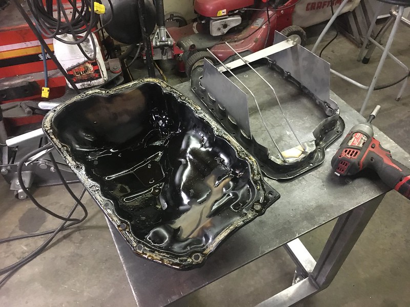
the factory oil pan

and less of it.
The Tig welder opens up the possibility of doing it out of aluminum. But theres a small hurdle

for whatever reason Mazda put this little whoop in the back of the pan. Making a pan flange out of 1/4” sheet wouldn’t be so bad but with this I either have to bend a piece ad weld it in or get a whole thicker piece of aluminum machined to accommodate it. I like neither of those options right now especially given my welding skills. So for now I’m gonna do a steel pan probably with baffles and look at it later. I really like the look of custom fabricated aluminum pans.

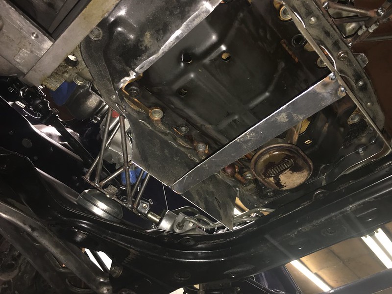
have a ton of room below actually. the pickup which I will probably reuse is in the factory location but the pickup tube was cut off because it hits the rack otherwise.

steering rack is the biggest hurdle because it and the oil pickup tube want to be in the same place. I think with a tighter radius bend the tube will be fine. I also think the pickup should sit further back in the middle of the pan.


this ended up being kinda ugly and many pieces. the less welding beads the better. So it’ll be used to get an idea of clearance and I’ll make a nice one based off of it. As i often do

Its working on my back, I have to lift the engine up a bit to get the pan on and off. Only like an inch though meaning removing the pan in the car isn’t too bad. Not many cars can you remove the entire oil pan without removing the subframe or part of it.
Thats all for now, going to try and get the pan done before I’m back to work. We’ll see if that even happens though as who knows we may be in full lockdown by then…
made a goof here where I welded on the inside of the bend and it obviously shrunk and made the angle tighter. So took some heat and bent them back out to where I could just get it bolted back on and then added more heat. fixed
took a large amount of time on again the belt sander but made this nice looking piece for the alternator
still need to make the end where the alt bolts to it thinner in order to align the belt. I also need to order the tube and opposing thread rod ends etc
now for one bit I’m not looking forward too
the factory oil pan
and less of it.
The Tig welder opens up the possibility of doing it out of aluminum. But theres a small hurdle
for whatever reason Mazda put this little whoop in the back of the pan. Making a pan flange out of 1/4” sheet wouldn’t be so bad but with this I either have to bend a piece ad weld it in or get a whole thicker piece of aluminum machined to accommodate it. I like neither of those options right now especially given my welding skills. So for now I’m gonna do a steel pan probably with baffles and look at it later. I really like the look of custom fabricated aluminum pans.
have a ton of room below actually. the pickup which I will probably reuse is in the factory location but the pickup tube was cut off because it hits the rack otherwise.
steering rack is the biggest hurdle because it and the oil pickup tube want to be in the same place. I think with a tighter radius bend the tube will be fine. I also think the pickup should sit further back in the middle of the pan.
this ended up being kinda ugly and many pieces. the less welding beads the better. So it’ll be used to get an idea of clearance and I’ll make a nice one based off of it. As i often do
Its working on my back, I have to lift the engine up a bit to get the pan on and off. Only like an inch though meaning removing the pan in the car isn’t too bad. Not many cars can you remove the entire oil pan without removing the subframe or part of it.
Thats all for now, going to try and get the pan done before I’m back to work. We’ll see if that even happens though as who knows we may be in full lockdown by then…
03-23-20, 02:27 PM
#273
Senior Member
Quite the build you are undertaking...inspiring! What are your impression of the those knock-off greddy gauges? they look actually nice but what is the accuracy like and would you recommend them? cheers
03-23-20, 05:31 PM
#274
Senior Member
Thread Starter
uhm hmm. they do look nice and they work decent. I havent done a back to back comparison with another gauge or sender but I did compare the CLT to what the 5.0's ECU was seeing and it was a few degrees different. But the senders were in different places.
My friends have them as well and so far we all like them especially for the price. they dont come with connectors or wire long enough to run to the engine bay so you do have to deal with that and the senders arent very robust after you remove them a few times but for the price I like them. They are a standalone gauge btw not connected to a control module like the real ones
My friends have them as well and so far we all like them especially for the price. they dont come with connectors or wire long enough to run to the engine bay so you do have to deal with that and the senders arent very robust after you remove them a few times but for the price I like them. They are a standalone gauge btw not connected to a control module like the real ones
05-18-20, 02:06 PM
#275
Senior Member
Thread Starter
Happy quarantine everyone! just kidding, here in Canada we never went to a full lockdown just heavy restrictions. Work never stopped because building condos is essential or something I guess. So all its really done is made it harder to get parts and material and cleared up my social calendar lol. Still having FOMO because my buddies are out cruising around but at least theres no drift events yet. I’m still quite a ways off from a running driving drifting car, as usual everything takes longer and costs more then you thought.
I also keep deciding to do things cooler and costlier ways, but I’ll be happy with the end product this way. I start to mock up something and it doesn’t fit like I had pictured so I spend more time thinking how to do things all while keep aesthetics and serviceability. Aesthetics have become a key part, I’m not wanting all this effort to be ruined by not liking how it looks in the end.
pickup up where I left off on the oil pan;
the first pan I cut up for the flange, I kinda decided I could do better. But not wasting the old one I used it to give me a good idea of clearances

fully flat this time
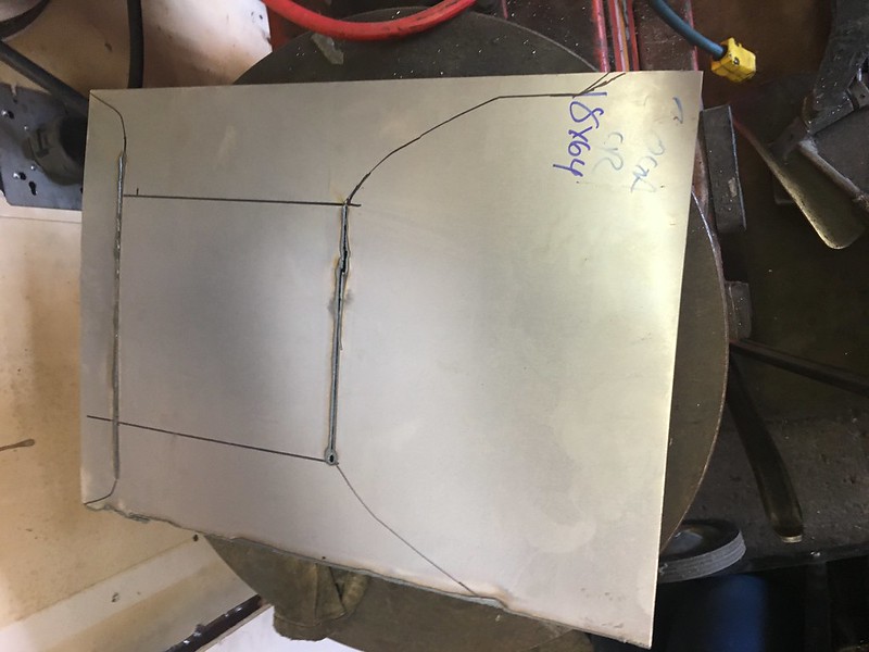
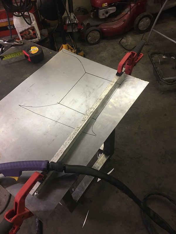
I had bought some 20 Ga sheet metal for this, probably could have gone thicker in hindsight. Using the plasma cutter to cut faster and make less waste

bend to shape

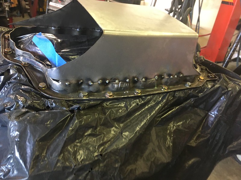
Leaving the mock block in the car and I wanted to be able to tack it without pulling it out so rather risky but I put a garbage bag to keep dust out and used the real deal engine

Same drill as before, I found that if I cut the areas that bend around on a curve going up from the flat sides they fit best


made some paper templates of the yet to be filled in areas

to get the curve shape I tacked it to a pipe and rolled in like a rolling pin on the welding bench

I also keep deciding to do things cooler and costlier ways, but I’ll be happy with the end product this way. I start to mock up something and it doesn’t fit like I had pictured so I spend more time thinking how to do things all while keep aesthetics and serviceability. Aesthetics have become a key part, I’m not wanting all this effort to be ruined by not liking how it looks in the end.
pickup up where I left off on the oil pan;
the first pan I cut up for the flange, I kinda decided I could do better. But not wasting the old one I used it to give me a good idea of clearances
fully flat this time
I had bought some 20 Ga sheet metal for this, probably could have gone thicker in hindsight. Using the plasma cutter to cut faster and make less waste
bend to shape
Leaving the mock block in the car and I wanted to be able to tack it without pulling it out so rather risky but I put a garbage bag to keep dust out and used the real deal engine
Same drill as before, I found that if I cut the areas that bend around on a curve going up from the flat sides they fit best
made some paper templates of the yet to be filled in areas
to get the curve shape I tacked it to a pipe and rolled in like a rolling pin on the welding bench