eage8's SSM/HPDE FC Turbo
 07-03-14, 11:16 AM
#501
the MAX links put me pretty darn close to 0*. I've actually been thinking lately to try to re-install them and then moving my center link from as shorter as it can be to as long as it can be on the solid bushings to see how much of a difference that'll make, but I haven't gotten around to it yet.
The rear camber I want to shoot for is between -1 and -1.5*.
 07-10-14, 10:57 PM
#502
So... my newish techedge wideband is dead.... luckily it's still under warranty. Shipping it out to Australia tomorrow  It's supposed to be good up to 19.5V, so I don't think it's because of my alternator issues, but who knows.
I'm also planning to mount my o2 sensor further down my exhaust, probably right after the down pipe (techedge recommends 3 feet from the turbo). Ordered a bung and a new o2 sensor (mine is most likely dead due to the fried wideband not heating it right while running)
It's supposed to be good up to 19.5V, so I don't think it's because of my alternator issues, but who knows.I'm also planning to mount my o2 sensor further down my exhaust, probably right after the down pipe (techedge recommends 3 feet from the turbo). Ordered a bung and a new o2 sensor (mine is most likely dead due to the fried wideband not heating it right while running)
07-21-14, 10:09 AM
#503
I autocrossed yesterday with no o2 sensor which was scary, but I don't have o2 correction enabled, so it was theoretically no different
It looks like I've completely fixed my fans which is awesome, I took the fan relays out of series, and put them on individual outputs on the mega squirt. I also staggered them a bit so one only turns on if the first one isn't cutting it.
I replaced the wire for my FFE trigger (not using stock cas wire anymore) with a 2 wire shielded wire, it worked awesome.
I treated my slicks with Formula V, which basically re-hydrates them, and that turned out pretty awesome, they were much more forgiving than normal and I did a decent amount better than I normally do.
first in SSM by 3.4 seconds... would have been second in XP behind a cobra kit car on Avons, beating 2 other cobra kit cars, a V8 MGB, and a 914 with a nascar v8 in it
I forgot to set my camera up, so you'll have to make due with pictures:
07-23-14, 08:01 PM
#504
after seeing how much my car was rolling at the last autocross I started looking into roll centers... because even though I corrected mine with my ball joints, I still had no idea where it actually was.
I found this cool tool online:

eage8's SSM FC RX7
The model doesn't quite match up with my car (it says my control arms are 4* pointed up, and my digital level says they're closer to 2.5-3*) but it's in the ball park... for a free tool, I'm not complaining. (most suspension modeling software is a few hundred dollars...)
my roll center seems to be about 1/2 an inch underground, which isn't ideal, but not terrible. I've seen people say it should be anywhere from just above the ground, to 2-4" above the ground... so it's definitely too low.
I'll probably put another 1/2" spacer on my ball joints which should put me 1 inch above ground with some room to spare if my measurements are off, plus every spacer I put in the control arm makes me loose a bit of camber which I can't get back because my control arms aren't adjustable length... (camber plates are maxed out)
making the roll center higher should make the car turn in better, and decrease roll, we'll see how it goes.
some reading on roll center if anyone is interested:
motoiq roll centers
I found this cool tool online:
eage8's SSM FC RX7
The model doesn't quite match up with my car (it says my control arms are 4* pointed up, and my digital level says they're closer to 2.5-3*) but it's in the ball park... for a free tool, I'm not complaining. (most suspension modeling software is a few hundred dollars...)
my roll center seems to be about 1/2 an inch underground, which isn't ideal, but not terrible. I've seen people say it should be anywhere from just above the ground, to 2-4" above the ground... so it's definitely too low.
I'll probably put another 1/2" spacer on my ball joints which should put me 1 inch above ground with some room to spare if my measurements are off, plus every spacer I put in the control arm makes me loose a bit of camber which I can't get back because my control arms aren't adjustable length... (camber plates are maxed out)
making the roll center higher should make the car turn in better, and decrease roll, we'll see how it goes.
some reading on roll center if anyone is interested:
motoiq roll centers
 Looks like all that effort is finally paying off.
 07-28-14, 02:32 PM
#509
eage8's SSM FC RX7
I'm not sure how much I trust this web app though, it looks like they're using SAI to calculate the roll center instead of the actual strut axis which is wrong... I really need to invest in some real software to start modeling stuff.
it's the roll center migration on the Y axis (up and down) vs. roll angle. so it's moving a lot...
the car is rolling a lot right now, but it's hard to tell how much fixing the roll center is going to fix that, they both depend on each other... as you can see in the pictures a few posts up, it's rolling too much though.
07-28-14, 02:41 PM
#510
I also started looking into the rear suspension. I'm not really sure how to go about finding the rear roll center. Theoretically it should just act like a semi-trailing arm, but I'm not sure if the additional camber gain will affect the roll center...
His is how you find a semi-trailing arm roll center:

and so doing some quick MS paint with some sub-ideal pictures:

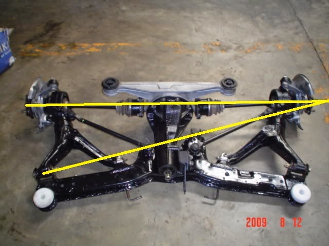
it looks like the pivot between the toe link and the outer control arm link (which I think is the virtual control arm) meets around where the outside edge of the tire is, so with 25.7" tires, that would make the roll center somewhere around 13" high maybe a bit lower than that... which seems high to me. and I'm not sure I'm calculating it right, but every reference book I have references something close to that above picture...
His is how you find a semi-trailing arm roll center:
and so doing some quick MS paint with some sub-ideal pictures:
it looks like the pivot between the toe link and the outer control arm link (which I think is the virtual control arm) meets around where the outside edge of the tire is, so with 25.7" tires, that would make the roll center somewhere around 13" high maybe a bit lower than that... which seems high to me. and I'm not sure I'm calculating it right, but every reference book I have references something close to that above picture...
Originally Posted by MotoIQ
On most cars the ideal location for the roll center is 2-4 inches above the ground for the front suspension and 4-10 inches above ground for the rear suspension with the rear roll center higher than the front.
07-28-14, 05:24 PM
#511
Make that ~6" not 13" which is probably right where I want it.
i'm going to aim for the front roll center to be somewhere around 2.66" so it's in the same area in that range that the rear roll center is in...
07-28-14, 07:42 PM
#512
trying to build a racecar
According to my suspension models the rear roll center is right around 6" high as well.
And with an unmodified front end (no changes to the lower ball joint or strut top), and ride height set so the LCA was parallel to the ground the RC should be about 1.1" above ground.
And with an unmodified front end (no changes to the lower ball joint or strut top), and ride height set so the LCA was parallel to the ground the RC should be about 1.1" above ground.
07-28-14, 09:09 PM
#513
so... I forgot about this issue:

That's with a 1.75" of spacers.
I stepped it down to 1.5" and it looks a lot better:

on the ground:

control arms are now about +1* pointed down (with the rear of the car jacked up, so it might actually be closer to 0), I'm pretty happy with that. I need to take both ball joints off again and grind them some more to allow them not to hit the brake rotor at full lock.
then I need to re-dial in the bump steer.
That's with a 1.75" of spacers.
I stepped it down to 1.5" and it looks a lot better:
on the ground:
control arms are now about +1* pointed down (with the rear of the car jacked up, so it might actually be closer to 0), I'm pretty happy with that. I need to take both ball joints off again and grind them some more to allow them not to hit the brake rotor at full lock.
then I need to re-dial in the bump steer.
 08-06-14, 11:05 AM
#516
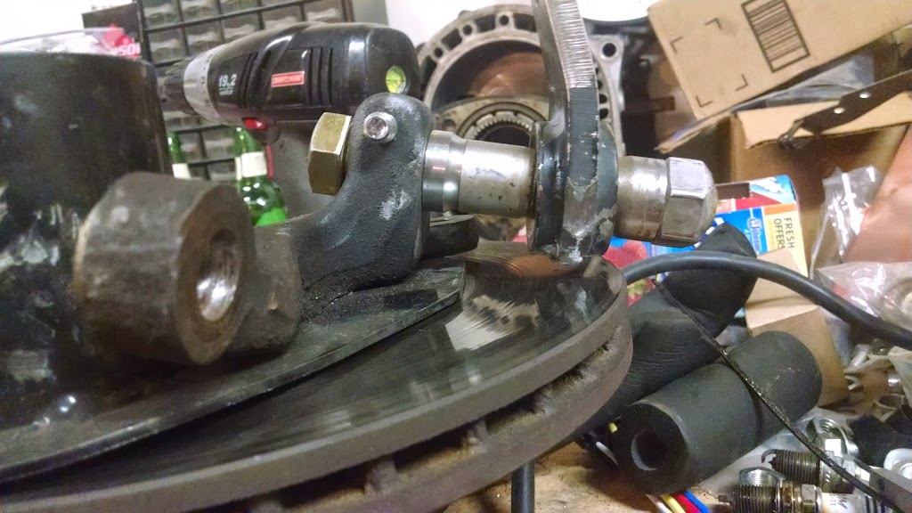
I got a set of spindles from a local forum member for so I will be drilling those out. I already have the nut and bolt. I have pictures of the joints I made and will probably post pictures of my work.
So I'm going to just shoot for parallel, or maybe slightly down for my spacing.
Is there a difference between mounting the ball joint in top or on bottom of the control arm?
If I mount it on top I could combine my ball joint and my sway bay end link bracket.
08-06-14, 11:11 AM
#517
I was looking into that and I could not find any. Also, I forgot if m18 bolts were available. Also making a space 0.5mm thick would not be possible.
I got a set of spindles from a local forum member for so I will be drilling those out. I already have the nut and bolt. I have pictures of the joints I made and will probably post pictures of my work.
So I'm going to just shoot for parallel, or maybe slightly down for my spacing.
Is there a difference between mounting the ball joint in top or on bottom of the control arm?
If I mount it on top I could combine my ball joint and my sway bay end link bracket.
you want the bearing to be at about 14-15* to the ball joint which is the angle of the ball joint taper. this way the bearing will be in the middle of it's travel when the control arm is parallel to the ground.
and yeah, just shoot for parallel or slightly down, from all my modeling that's pretty much right where you want it. but make sure you're measuring the virtual control arm level (the line from the control arm pivot bolt to the center of the bearing.)
08-06-14, 11:11 AM
#518
I was talking to someone recently and he was talking about how the fc sway bars bind. I also remembered you telling me you heard about the st sways binding issue. If the bind was only related to the end links, I could reposition the end link bracket so it does not bind. I saw where the st sways would bind, especially with stock end links. My stock end links were chewed up from the angle the st bar was at.
Even with the Mazdatrix end links, I flipped the male end of the link at the control arm side to gain every mm of cleanse to keep from binding
Even with the Mazdatrix end links, I flipped the male end of the link at the control arm side to gain every mm of cleanse to keep from binding
08-06-14, 11:34 AM
#519
Josh18_2k had binding issues with the ST bar.
I had whiteline bar (I don't think it's available anymore) which I didn't realize until after I took it off that it's designed to use a completely different end link setup with both the pivots in the same direction. and the pivots and bar arms further in.
AWR has a similar setup for their bar (which mounts on top of the frame rail and is completely different) but I'm not sure they make them anymore either.
If I were still running a sway bar, I would make a replacement sway bar bracket that makes the end link pivot on the same axis as the sway bar and it should solve most of the binding issues.
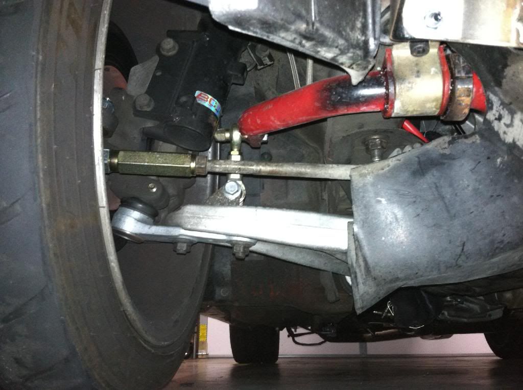
you can see the brackets and the endlinks of the whiteline bar:

AWR's endlink mount:

I had whiteline bar (I don't think it's available anymore) which I didn't realize until after I took it off that it's designed to use a completely different end link setup with both the pivots in the same direction. and the pivots and bar arms further in.
AWR has a similar setup for their bar (which mounts on top of the frame rail and is completely different) but I'm not sure they make them anymore either.
If I were still running a sway bar, I would make a replacement sway bar bracket that makes the end link pivot on the same axis as the sway bar and it should solve most of the binding issues.
you can see the brackets and the endlinks of the whiteline bar:
AWR's endlink mount:
08-07-14, 10:38 AM
#520
Josh18_2k had binding issues with the ST bar.
I had whiteline bar (I don't think it's available anymore) which I didn't realize until after I took it off that it's designed to use a completely different end link setup with both the pivots in the same direction. and the pivots and bar arms further in.
AWR has a similar setup for their bar (which mounts on top of the frame rail and is completely different) but I'm not sure they make them anymore either.
If I were still running a sway bar, I would make a replacement sway bar bracket that makes the end link pivot on the same axis as the sway bar and it should solve most of the binding issues.
you can see the brackets and the endlinks of the whiteline bar:
AWR's endlink mount:
 I haven't had a chance to drive my car yet, its a big project. What front sway bar setting do most people use for their fc's? My st bar has only 2 settings
08-07-14, 10:45 AM
I haven't had a chance to drive my car yet, its a big project. What front sway bar setting do most people use for their fc's? My st bar has only 2 settings
08-07-14, 10:45 AM
#521
I have an RB bar with the Mazdatrix end links. My front swaybar is relocated forward a bit, and I dont get any binding at all.
It was very obvious the stock and RB end links would not work as soon as I relocated the bar, so I can't see any of the adjustable bars working without heim joint style end links.
It was very obvious the stock and RB end links would not work as soon as I relocated the bar, so I can't see any of the adjustable bars working without heim joint style end links.
08-07-14, 10:51 AM
#522
I have an RB bar with the Mazdatrix end links. My front swaybar is relocated forward a bit, and I dont get any binding at all.
It was very obvious the stock and RB end links would not work as soon as I relocated the bar, so I can't see any of the adjustable bars working without heim joint style end links.
It was very obvious the stock and RB end links would not work as soon as I relocated the bar, so I can't see any of the adjustable bars working without heim joint style end links.
The binding everyone is talking about is just the binding of the endlinks, right?
08-07-14, 10:57 AM
#523
again, I don't have the ST bar, but Josh said it didn't bind nearly as much on the softer setting, so that's where he ran his.
I have no idea where josh saw binding... it sounded like it was the bar itself though.
LOF: even with heim joints, I think mine was still binding because the heims are perpendicular to each other, so as the bar went through it's arc they would run out of travel. but that's it's own special case...
Everyone should just put 900 lb springs on their car like me

 08-07-14, 11:10 AM
#525
I'm thinking about integrating my end link bracket with my lower ball joint to save a little weight, and then I can also reposition the endlink so it is not angled and has less of a chance of binding. My only debate is that angle of the bearing so it has the most movement. I did not have the ability to bend the 3/8"thick steel I used for the body of the ball joint, so I'm loosing a little of angle there already. I haven't had a chance to drive my car yet, its a big project. What front sway bar setting do most people use for their fc's? My st bar has only 2 settings
I haven't had a chance to drive my car yet, its a big project. What front sway bar setting do most people use for their fc's? My st bar has only 2 settingsthe bearing only has 26* of articulation