Something completely different - a very long term tube chassis project


Thread Starter
spoon!
Joined: Sep 2002
Posts: 1,208
Likes: 50
From: Dousman, WI
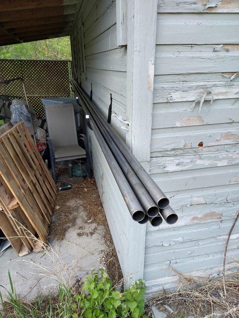
I don't have the quote from last year... was about $3.10 per foot for the 1.5x0.065 for the main (non-safety) structure and got 130 feet to start. Will need to put another order in but that'll get me going.
Thread Starter
spoon!
Joined: Sep 2002
Posts: 1,208
Likes: 50
From: Dousman, WI
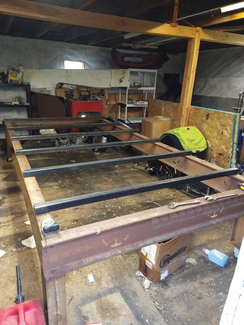
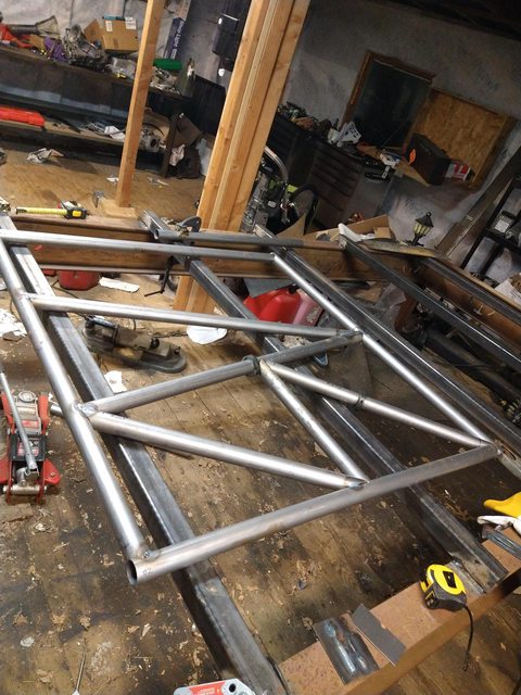
Maybe not the sexiest thing, but got cross-tubes for the chassis table cut out. Just need to get some stick electrodes and some grinding consumables and will have that done, nice and flat and sturdy.
Thread Starter
spoon!
Joined: Sep 2002
Posts: 1,208
Likes: 50
From: Dousman, WI
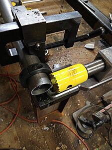
OK, notcher modified and mounted!
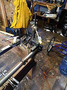
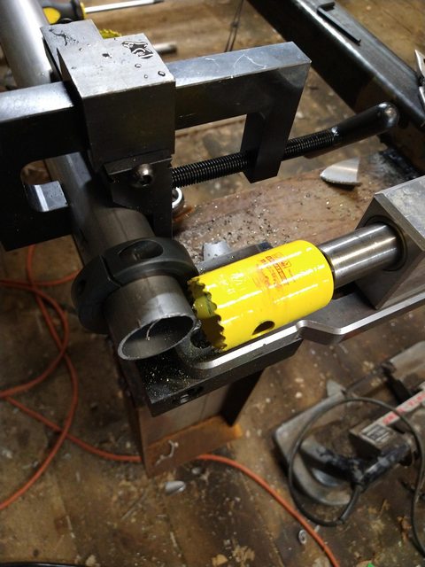
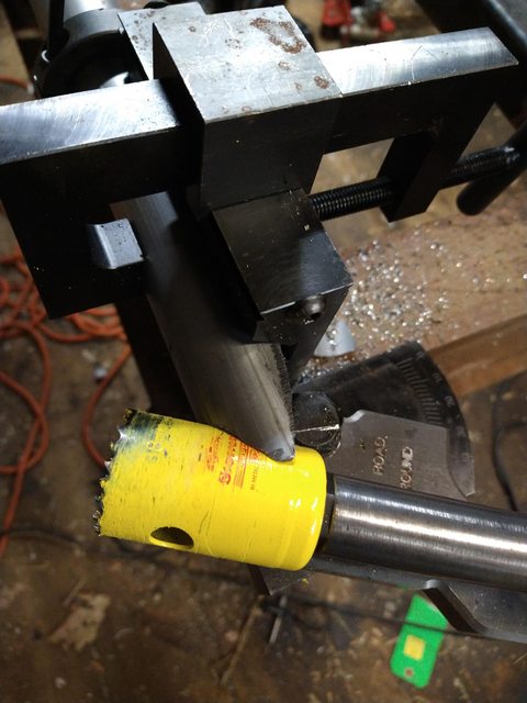
Chinese clone of a JD2 Notch Master, with a SWAG Offroad Reacharound, bolted to the chassis table directly. Nice and beefy. Drill is an OLD Black and Decker that may be older than me but nice and full of torque. The reach around lets me use long hole saws and get to notches that are much closer to parallel to the tube than I'd be able to do otherwise.

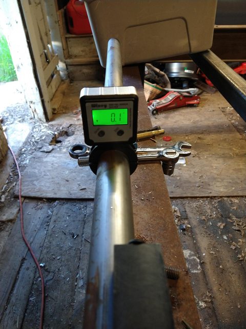
Digital angle gauge from... god I don't know. Correlates to real stuff that I checked against. Is tenth of a degree excess accuracy for things? I don't know, maybe, whatever.
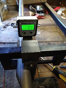
Shimmed the whole notchmaster to... pretty close to level. Why does that matter?

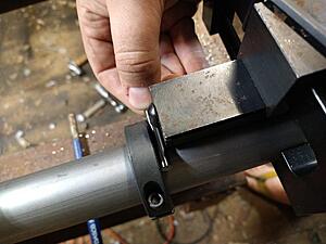
So that's a split 1.5" collar with flats on it. So some of the tubes have notches in more than one plane, or even if I want to notch both sides of a tube it's pretty nice to have a reference for rotation. The idea is that collar goes on, is zeroed relative to the notcher, then stays on until the tube is fully notched.
Tonight I'm basically going to make a bunch of coupons notched to various angles and get my welding dialed in... it's been a while and I have no doubt that I could stand to get the rust off. I'll also take pictures of my solution to the fact that I'll be welding on evenings where it's Too ******* Hot to be wearing proper gear.
Chinese clone of a JD2 Notch Master, with a SWAG Offroad Reacharound, bolted to the chassis table directly. Nice and beefy. Drill is an OLD Black and Decker that may be older than me but nice and full of torque. The reach around lets me use long hole saws and get to notches that are much closer to parallel to the tube than I'd be able to do otherwise.
Digital angle gauge from... god I don't know. Correlates to real stuff that I checked against. Is tenth of a degree excess accuracy for things? I don't know, maybe, whatever.

Shimmed the whole notchmaster to... pretty close to level. Why does that matter?
So that's a split 1.5" collar with flats on it. So some of the tubes have notches in more than one plane, or even if I want to notch both sides of a tube it's pretty nice to have a reference for rotation. The idea is that collar goes on, is zeroed relative to the notcher, then stays on until the tube is fully notched.
Tonight I'm basically going to make a bunch of coupons notched to various angles and get my welding dialed in... it's been a while and I have no doubt that I could stand to get the rust off. I'll also take pictures of my solution to the fact that I'll be welding on evenings where it's Too ******* Hot to be wearing proper gear.
Thread Starter
spoon!
Joined: Sep 2002
Posts: 1,208
Likes: 50
From: Dousman, WI
Well, OK, so the temperature crashed and now I haven't needed to do the coolshirt stuff? Which is nice but weird. Made a bunch of test coupons mitered at various angles - notcher setup works to at least 20 degrees from parallel which is pretty cool. I'm going to TIG weld a bunch of stuff to get back in practice before I get to real stuff.
Anyway, got to asking fellow competitors about LSD options for the quick change I have and... turns out that it's really marginal behind a 13B, to the point where the company got tired of supporting them because they kept breaking and won't sell them to rotary guys anymore.
Ugh.
So! The transmission I'm planning on using has drop gears so I can just change a pair of gears there for the same functionality... so that's OK... and it turns out that there's advantages to some aspects of the stock rear axle in the sense of available LSDs, relatively compact and ... it's not that bad, and it'll hold the power I'll be making. I mean, the housing is but the solution to that is well proven from Ford 9" stuff.
Yes, I'm talking a fabricated Mazda rear axle housing.
That combined with some stuff I'm working on getting from aussieland may actually end up a better solution. If a weird one.
Charlie Clark has a full floating rear axle in his EP RX7. It uses the center part of the OE housing with axle tubes replaced by mini-GN stuff from Speedway Engineering. I believe Moser made the floating axles. Jesse Prather had the same thing in the EP RX7 he built in 16-17.
I will check with Charlie to see he has any engineering drawings or specs.
If I were allowed to have a different rear end housing, I would do something with a 7.5 Ford and just make more than one axle housing/gear combination. Changing out the entire housing wouldn't be an issue with dry break hoses for the brakes. Also, I know the rear diff ratio each of the tracks so it would be a job done in the shop. There are allot of diff and gear choices and he important bits (bearings, 28 Spline axles) are the same as an 8.8 Ford. Also compared to a 9" Ford these rear end types use less HP.
Thread Starter
spoon!
Joined: Sep 2002
Posts: 1,208
Likes: 50
From: Dousman, WI
I actually already have drawings for the floater ends I was going to put on the QC (4x100 is the key part) so that part's not too hard. And I'm going to pursue having Mark Williams or someone broach side gears to Ford 28 spline which I think will work and makes ordering axles from Speedway or someone easier. It's just slightly annoying because I thought this was all figured out already but oh well, I can just go back to my old EProd notes.
Thread Starter
spoon!
Joined: Sep 2002
Posts: 1,208
Likes: 50
From: Dousman, WI
https://msfracingcomponents.com.au/p...-diff-carrier/ And there's this sucker, of course, plus the OS Giken diffs that fit.
Thread Starter
spoon!
Joined: Sep 2002
Posts: 1,208
Likes: 50
From: Dousman, WI
So drew up a fabricated style housing ala Ford 9", but for the Mazda diff carrier. Back plate not designed yet because I want to scan in a diff carrier with a ring gear but most of it's there. Might make the center section a bit wider but whatever.
Thread Starter
spoon!
Joined: Sep 2002
Posts: 1,208
Likes: 50
From: Dousman, WI
OK, so how am I doing this without ******* things up? Follow along!

Very high tech drawing... snork. OK. Rather than make drawings in the CAD sense I just figured I'd mark stuff up with dimensions that made sense to me. So take tube #1; 43" at the narrowest point, IE at the crotch of both notches.
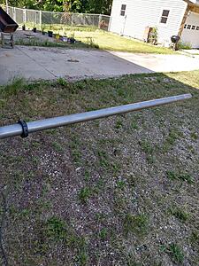
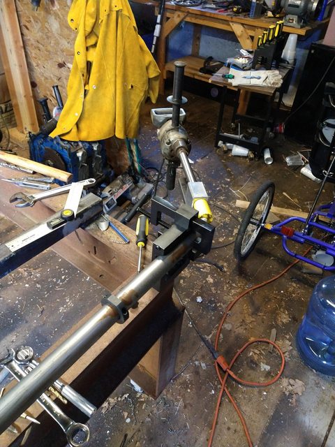
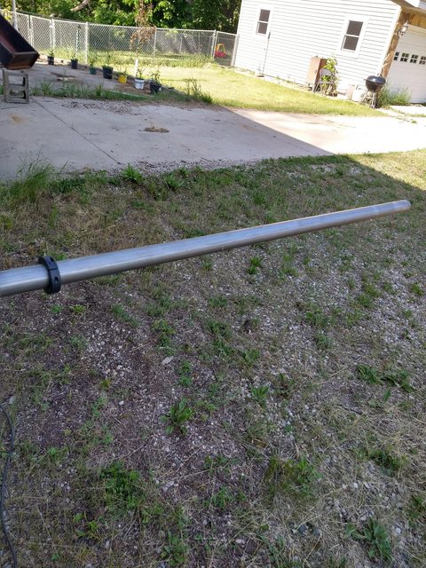
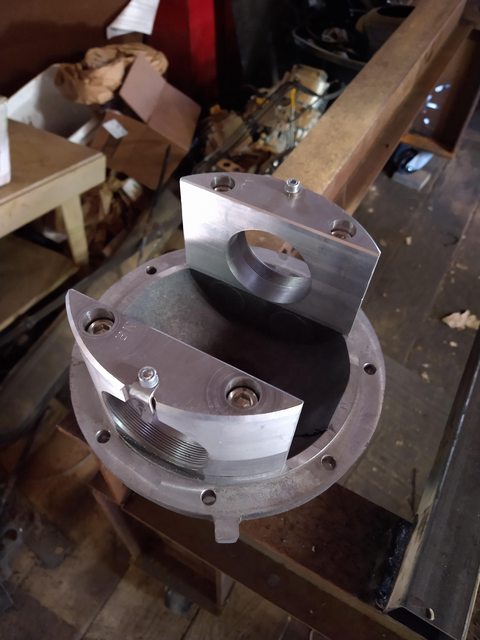
Tube sticking out of my steel rack with 2 piece collar as guide.
And where I cut it to. 1.5" extra to accommodate the notches and stuff.
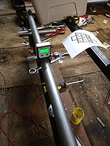
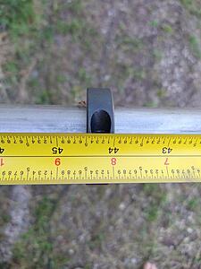
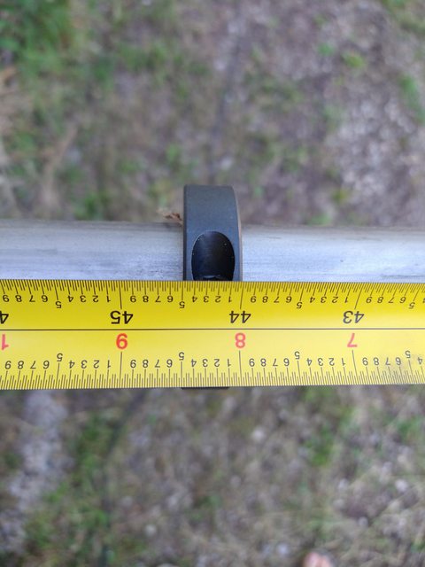
Split collar with flats and angle cube to make sure stuff is staying in plane - IE once I put tubes against the notches on both ends, those tubes will be parallel.
Split collar aligned 43.0" outside edge to crotch of other notch. Cutting first notch not photographed because screw it, I forgot.
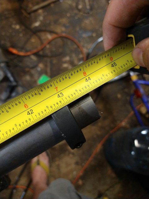
And butted up against the hole saw.
End result, the cut was within a couple hundredths of an inch; I'll work to do better once I get used to hole saw tolerances.
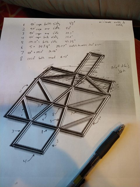
Very high tech drawing... snork. OK. Rather than make drawings in the CAD sense I just figured I'd mark stuff up with dimensions that made sense to me. So take tube #1; 43" at the narrowest point, IE at the crotch of both notches.
Tube sticking out of my steel rack with 2 piece collar as guide.
And where I cut it to. 1.5" extra to accommodate the notches and stuff.

Split collar with flats and angle cube to make sure stuff is staying in plane - IE once I put tubes against the notches on both ends, those tubes will be parallel.
Split collar aligned 43.0" outside edge to crotch of other notch. Cutting first notch not photographed because screw it, I forgot.
And butted up against the hole saw.
End result, the cut was within a couple hundredths of an inch; I'll work to do better once I get used to hole saw tolerances.
Thread Starter
spoon!
Joined: Sep 2002
Posts: 1,208
Likes: 50
From: Dousman, WI
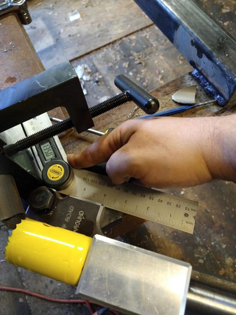
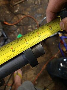
More progress! But first a demonstration of a not so hypothetical scenario... see I'm getting better at getting miter lengths exactly right now that I figured out what I was doing wrong, but it's humid out, I'm sweating like a pig, and sometimes I mess up. So first, keep in mind the split collar with the wrench flats and the angle finder - that stays on the tube until the fitup is as good as it's going to get. So I can always put it back into the notcher and preserve angles. So slide it all the way to the holesaw like so:

And there's a reference for where it's cut to now. Which is in this case about a quarter inch too long.
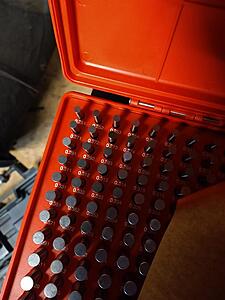
So I grab my handy dandy 0.251" pin gauge... (what's a thou between friends?) (OK really I'm using a holesaw, I don't need this precision but it's sitting right there)
... and use it to set a split collar standing off from that side of the notcher the thickness of that pin gauge. Just slide it forwards that bit, voila, 0.251" (ish, lol) more notch depth.
Where I left off for the night. Most welds are at best tacked, a bunch of joints are just held together by clamps or tension, but you get the idea. Obviously there's an order it has to get finish welded in.
And there's a reference for where it's cut to now. Which is in this case about a quarter inch too long.
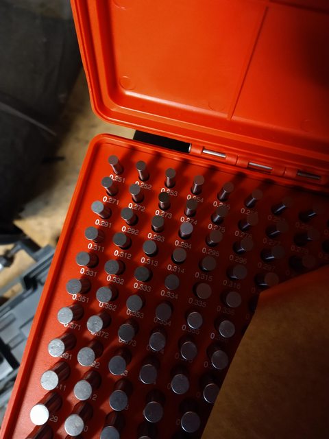
So I grab my handy dandy 0.251" pin gauge... (what's a thou between friends?) (OK really I'm using a holesaw, I don't need this precision but it's sitting right there)

... and use it to set a split collar standing off from that side of the notcher the thickness of that pin gauge. Just slide it forwards that bit, voila, 0.251" (ish, lol) more notch depth.
Where I left off for the night. Most welds are at best tacked, a bunch of joints are just held together by clamps or tension, but you get the idea. Obviously there's an order it has to get finish welded in.
Thread Starter
spoon!
Joined: Sep 2002
Posts: 1,208
Likes: 50
From: Dousman, WI
Ok so this is still going - just different priorities now that I have a job again and kid's in daycare and... well. Progress was faster for a while because I had nothing else going on, now I'm working on a bunch of stuff that I didn't have the ability to afford while I wasn't employed, like fixing the barn.
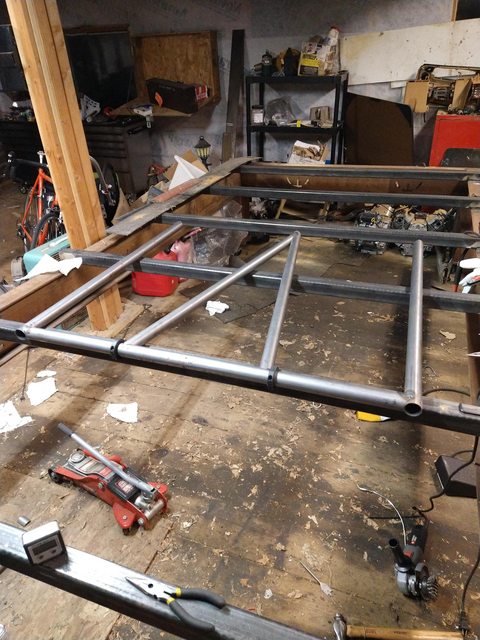
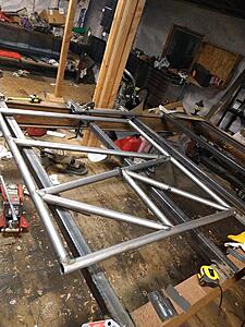
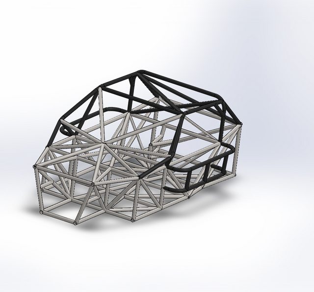
Anyway, Mk15 on the chassis now! Yes it looks complicated but I promise it's not as bad as it looks.
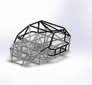
Anyway, Mk15 on the chassis now! Yes it looks complicated but I promise it's not as bad as it looks.
Thread Starter
spoon!
Joined: Sep 2002
Posts: 1,208
Likes: 50
From: Dousman, WI
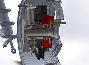
I started modelling front uprights and came to a realization that I'm a lot happier with... though it'll probably be a little more expensive it should be nigh bulletproof.
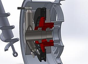
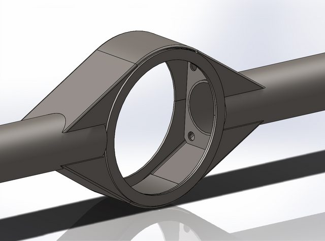
Old design... red parts are aluminum. The hub contains the bearing and rotates on the spindle. This is fine and massively better than stock, but... I'm unsatisfied with the gussets - imagine there's a grease seal on the inside of the hub (forgot to put one into the assembly) and look how little gussets would add.
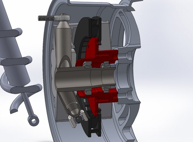
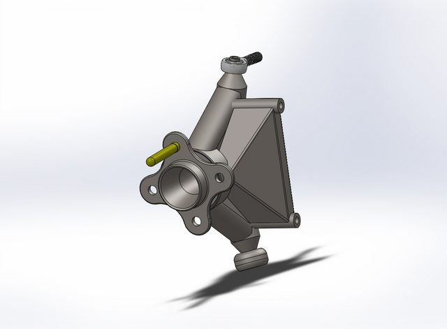
New design. Bearings are spread across wider area (more stiffness) and gussets have room to go out to the outer bearing too. And the brake rotor and hat can just come off. And it uses press-in studs instead of screwed in, and the bearings ride between steel and steel vs steel and aluminum, and...
Anyway. A bit more costly to make probably but I think I like the tradeoffs.
Old design... red parts are aluminum. The hub contains the bearing and rotates on the spindle. This is fine and massively better than stock, but... I'm unsatisfied with the gussets - imagine there's a grease seal on the inside of the hub (forgot to put one into the assembly) and look how little gussets would add.
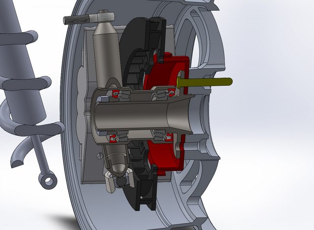
New design. Bearings are spread across wider area (more stiffness) and gussets have room to go out to the outer bearing too. And the brake rotor and hat can just come off. And it uses press-in studs instead of screwed in, and the bearings ride between steel and steel vs steel and aluminum, and...
Anyway. A bit more costly to make probably but I think I like the tradeoffs.
Thread Starter
spoon!
Joined: Sep 2002
Posts: 1,208
Likes: 50
From: Dousman, WI
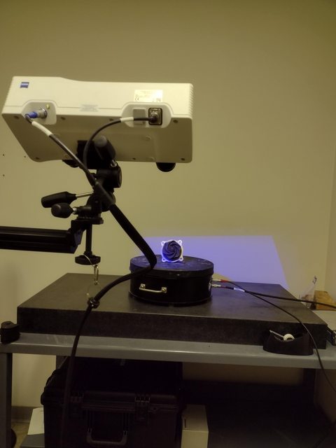
Getting back in the swing of things... new barn doors on barn are as-done-as-they're-going-to-be this season so can get back to the chassis. And got trained on the Zeiss blue light scanner at work.
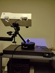
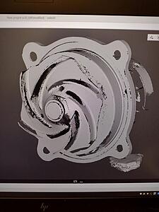
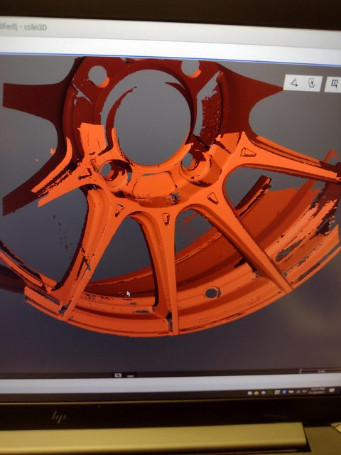
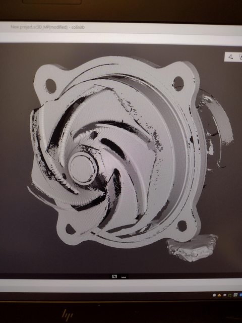
So this is a scan of an EMP Stewart Pro Series water pump cartridge - been intending to do this for purpose of making a new housing for rotary use. Can't see it on the crummy phone-photo-of-work-laptop-screen but the scan resolution is high enough detail to see machining marks. And then on the turntable, a PFC ZR34! Great calipers honestly; compatible with the Wilwood superlite, but monobloc
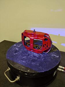
Look at that sucker; OK it's not new but still good.

Screen picture of what the scanner is doing; I like how it looks almost arty

And after a few scans, that's enough data to reverse engineer. Or at least it has all the critical points where I can plunk it into CAD to figure out how to fit it into the wheels. Which is Monday, after which I'll be able to do good, accurate mockup in CAD. Over the weekend I'm bead blasting a couple front covers and scanning those next week... the QC department at work's factory (in Mexico) is eventually going to get the scanner now that engineering isn't using it as much, so want to get a bunch of important-to-my-purposes stuff done ASAP.
So this is a scan of an EMP Stewart Pro Series water pump cartridge - been intending to do this for purpose of making a new housing for rotary use. Can't see it on the crummy phone-photo-of-work-laptop-screen but the scan resolution is high enough detail to see machining marks. And then on the turntable, a PFC ZR34! Great calipers honestly; compatible with the Wilwood superlite, but monobloc

Look at that sucker; OK it's not new but still good.

Screen picture of what the scanner is doing; I like how it looks almost arty
And after a few scans, that's enough data to reverse engineer. Or at least it has all the critical points where I can plunk it into CAD to figure out how to fit it into the wheels. Which is Monday, after which I'll be able to do good, accurate mockup in CAD. Over the weekend I'm bead blasting a couple front covers and scanning those next week... the QC department at work's factory (in Mexico) is eventually going to get the scanner now that engineering isn't using it as much, so want to get a bunch of important-to-my-purposes stuff done ASAP.
Thread Starter
spoon!
Joined: Sep 2002
Posts: 1,208
Likes: 50
From: Dousman, WI
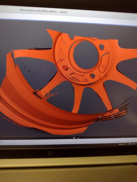
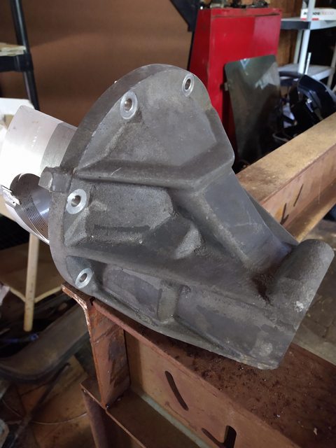
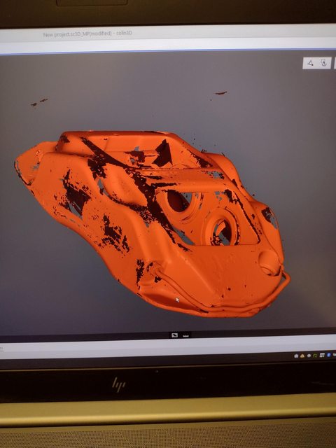
And now a 12A front cover; I intend to reverse engineer both this and a 13B-REW one and make a mashup where the REW timing setup replaces the 12A distributor hole, but with the 12A motor mounts and stuff.
Thread Starter
spoon!
Joined: Sep 2002
Posts: 1,208
Likes: 50
From: Dousman, WI
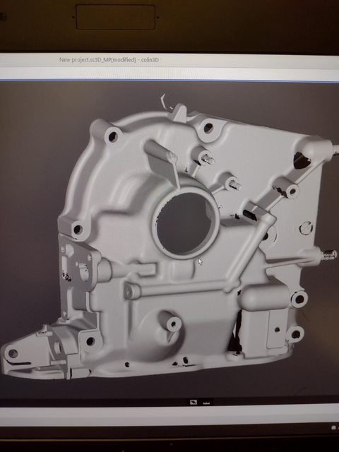
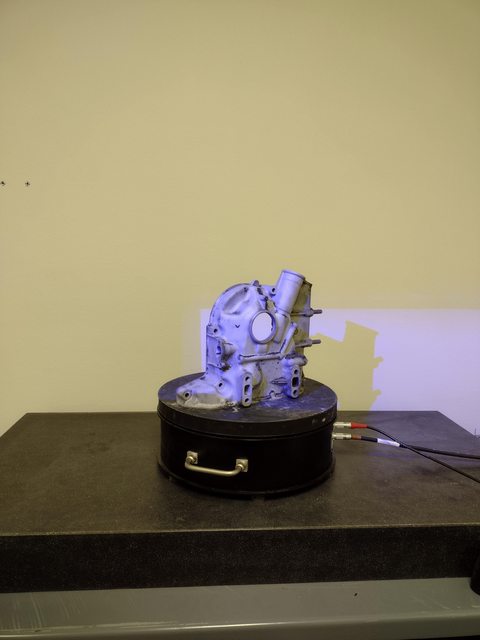
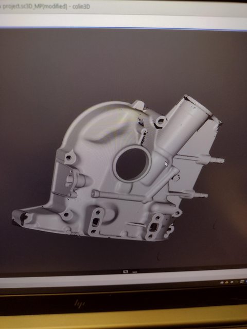
And there's the REW front cover. Handling the reverse engineering into CAD part will be a pain unless I figure out a better way, but now I have dimensionally accurate data I can pick at to get there.