
SCCA Super Touring U Build

Thread Starter


Joined: Nov 2006
Posts: 1,578
Likes: 288
From: Parkville, Mo
The Deka AGM battery is now mounted and I have fitted the positive battery cable. Also got the Transponder mounted and wired into the hot/ground for the fuel pumps. I wired it into the fuel pumps so that the transponder would be on whenever the car was moving.
Up next is some finishing touches on the front suspension
Up next is some finishing touches on the front suspension


Thread Starter
Joined: Nov 2006
Posts: 1,578
Likes: 288
From: Parkville, Mo
Thanks guys. I should have some photo updates in a week or two. The projects that I will be detailing include new camber plates made of steel and new front lower control arms that are adjustable for length. I am also swapping out my 12A cross member for a GSL/SE cross member.
Earlier this week I connected up the battery and turned on the main/ignition circuits. I am happy to report that none of the magic smoke escaped the wring and everything worked as planned. The gauge lights even worked.
Earlier this week I connected up the battery and turned on the main/ignition circuits. I am happy to report that none of the magic smoke escaped the wring and everything worked as planned. The gauge lights even worked.
It looks like the pictures disappeared from your early posts (mid 2012). I realize it is a pain, but any chance of re-posting some of them, in particular those related to your front strut and brake modifications. I am trying to do some changes for a Chumpcar and any ideas/pictures would be great. One thing I am looking at is machining the rotor off an FB rotor/hub to make a hub that could be used to bolt a separate rotor to. Not sure about the spacing and such, but will post any results.
Carl
Carl
Thread Starter
Joined: Nov 2006
Posts: 1,578
Likes: 288
From: Parkville, Mo
It looks like the pictures disappeared from your early posts (mid 2012). I realize it is a pain, but any chance of re-posting some of them, in particular those related to your front strut and brake modifications. I am trying to do some changes for a Chumpcar and any ideas/pictures would be great. One thing I am looking at is machining the rotor off an FB rotor/hub to make a hub that could be used to bolt a separate rotor to. Not sure about the spacing and such, but will post any results.
Carl
Carl
I have seen people do what you are describing on a FOX mustang - they machined the rotors off of a 5 lug brake rotor and put a bigger hat/rotor on it. They used to break hubs on a regular basis. When that happened the front wheel would come off the car. I saw this in person at Heartland Park at the end of the main straight. So based on this, I can't recommend this approach.
The GSL front rotor works okay for speeds up to 110MPH as long as you have good air ducts, racing pads and racing fluid. I ran them on my IT7 car and it weighed 2450-2500lbs and never had any brake fad. The GSL/SE hub is a bad design and they do fail in racing - do not use them.
If the GSL brakes are not big enough, the brake kit that you want is made by KC Raceware - KC Raceware It replicates a GSL/SE front hub/rotor using an aluminum hub that doesn't fail and a Coleman Racing rotor. The way it is made, bigger rotors could be bolted to the hub. Talk to Charlie Clark about options.
I generally agree with you on the stock brakes being adequate for IT7 when equipped with good brake ducts, as that is what I have used successfully for years. My chump buddies though think we need better brakes (there appears to be a problem with the hydraulics and I know that should be fixed first). Just for my own entertainment I am interested in going through the upgrade process.
Interesting comments on machining the rotors off. The only advantage I could see is that we could retain 4x110 all the way around.
I noticed that you seem to be a machinist. Did you by any chance get the dimensions of the Re-Speed bearing spacer? If so, would you be willing to send or post? How about just the outside dimensions?
I will contact KC raceware about their modified hubs and big brake stuff too. A couple of months ago I came across an Australian company that has some pretty interesting stuff for RX7's MSF Racing Components.
You STU build is really impressive and I have enjoyed going through (following) the updates.
Regards,
Carl
Thread Starter
Joined: Nov 2006
Posts: 1,578
Likes: 288
From: Parkville, Mo
Most people that think that GSL brakes don't work are guilty of using them too much 
I'm not a machinist, I just have access to cool machine tools.
When I got the kit from RE Speed we looked at the bearing spacer that came in the kit and determined that we didn't have the tools necessary to create the same finish. There are some people trying to replicate the kit - check out this thread https://www.rx7club.com/1st-generati...1985-a-830018/
I looked at the stuff from MSF Racing recently. Spendy but I like it.
If I decide to go to bigger brakes/tires/wheels on my car I will change the spindles either by fitting a Pinto over the FB spindles or do an FC sub frame with SN95 spindles
The KC Raceware hubs are available in 4x110mm or 4x114.3
Thanks for the encouragement
Thread Starter
Joined: Nov 2006
Posts: 1,578
Likes: 288
From: Parkville, Mo
Camber Plates
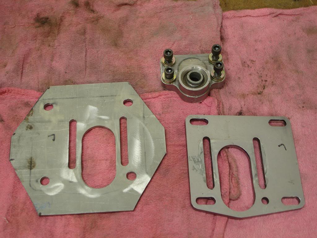
The Ground Control camber plates on my racecar had seen better days. 10+ years of curb hopping and off track excursions had bent both of them and caused one of them to crack. Replacing them with another set from Ground Control really wouldn't work because the car will now have stiffer springs, strut towers that are not going to flex and the plates will be mounted on the top of the tower. I am mounting the plates to the top of the tower to make spring/strut changes easier.
David Long at Santa Fe Garage (Santa Fe Garage Automotive Services in Independence, MO) copied the ground control plates in 5/16" cold rolled steel using a mill/drill. I then finished them on a belt sander and powder coated them. I also doubled the number of studs holding them to the car.
Old and new
Fitted to the car
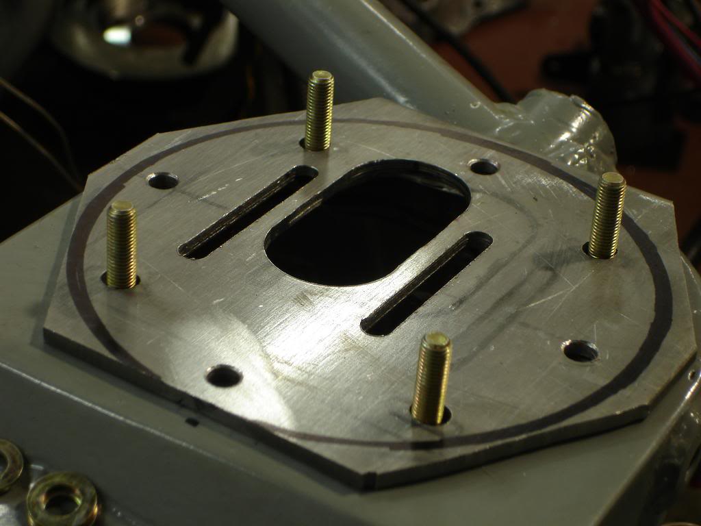
Shaped and extra studs added. These are 5/16 bolts that are welded to the tower

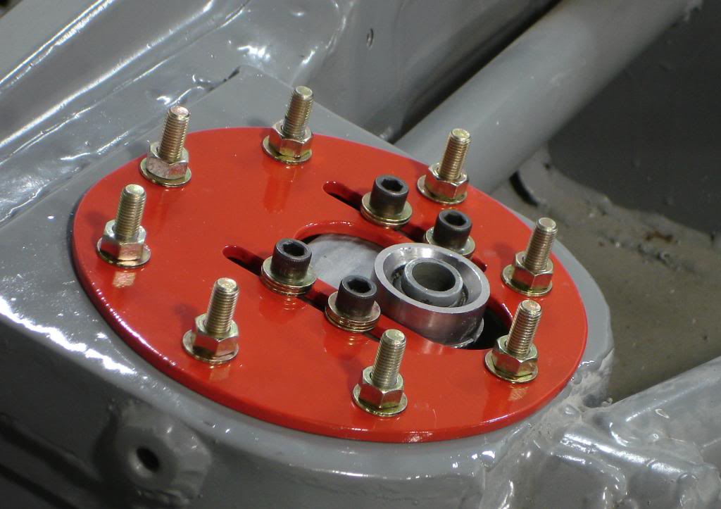
Finished

David Long at Santa Fe Garage (Santa Fe Garage Automotive Services in Independence, MO) copied the ground control plates in 5/16" cold rolled steel using a mill/drill. I then finished them on a belt sander and powder coated them. I also doubled the number of studs holding them to the car.
Old and new

Fitted to the car

Shaped and extra studs added. These are 5/16 bolts that are welded to the tower

Finished


Thread Starter
Joined: Nov 2006
Posts: 1,578
Likes: 288
From: Parkville, Mo
Thanks Mr TransAm!
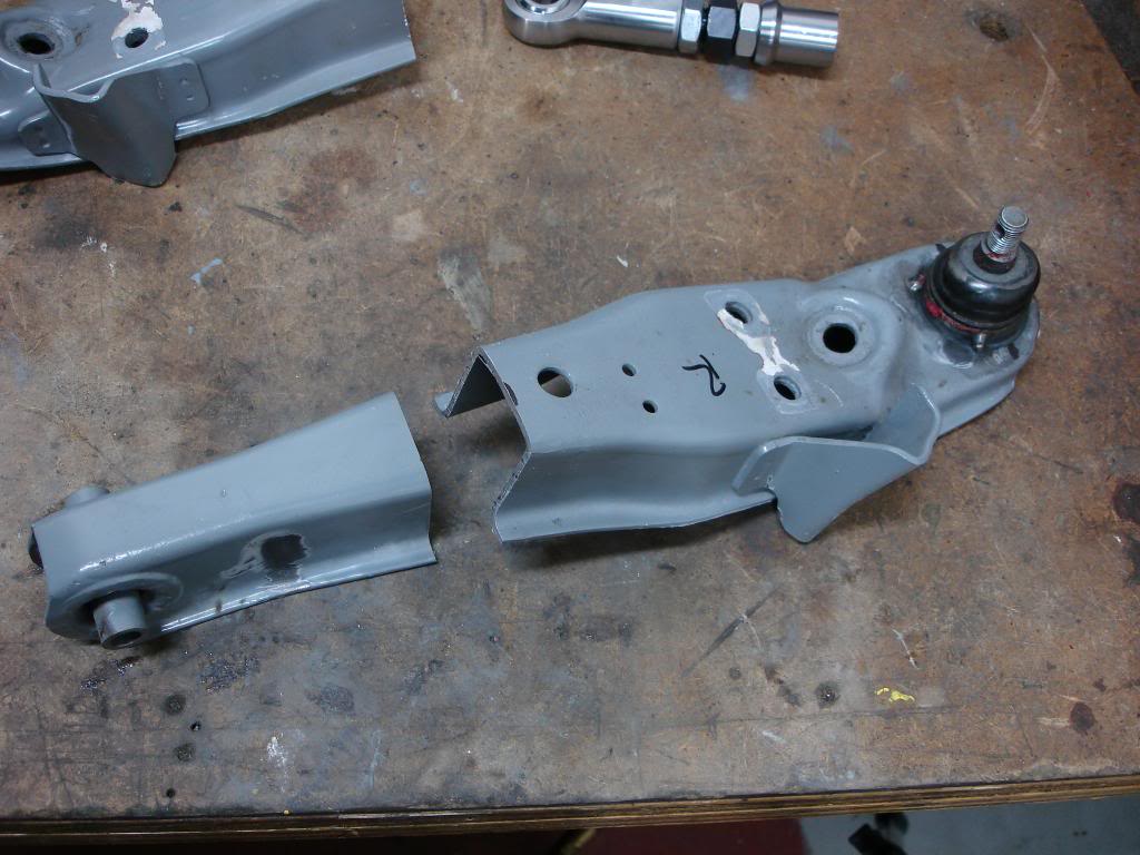
So just got started on the front lower control arms. These will be adjustable for length to make up for the loss of track width caused by using 2" spacers under the struts. They will adjust from the stock length to around 14" safely. I'm thinking that I will need about 1/2 inch tops. This will be another way to get negative camber.
The stock arms have 1/2 spherical bearings at the chassis mount. Other mods include some clearancing in the ball joint end of the arm and the ball joints have been tack welded into place. Laying next to them are the new parts.

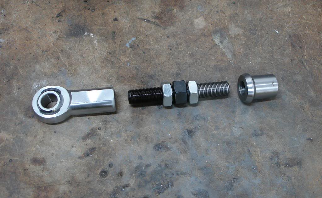
Here is what I will use the make the arms adjustable - QA1 5/8 female RH rod end, double ended 5/8 adjuster with RH and LH threads and a 5/8 LH tube end.
We are committed now!
All welded up
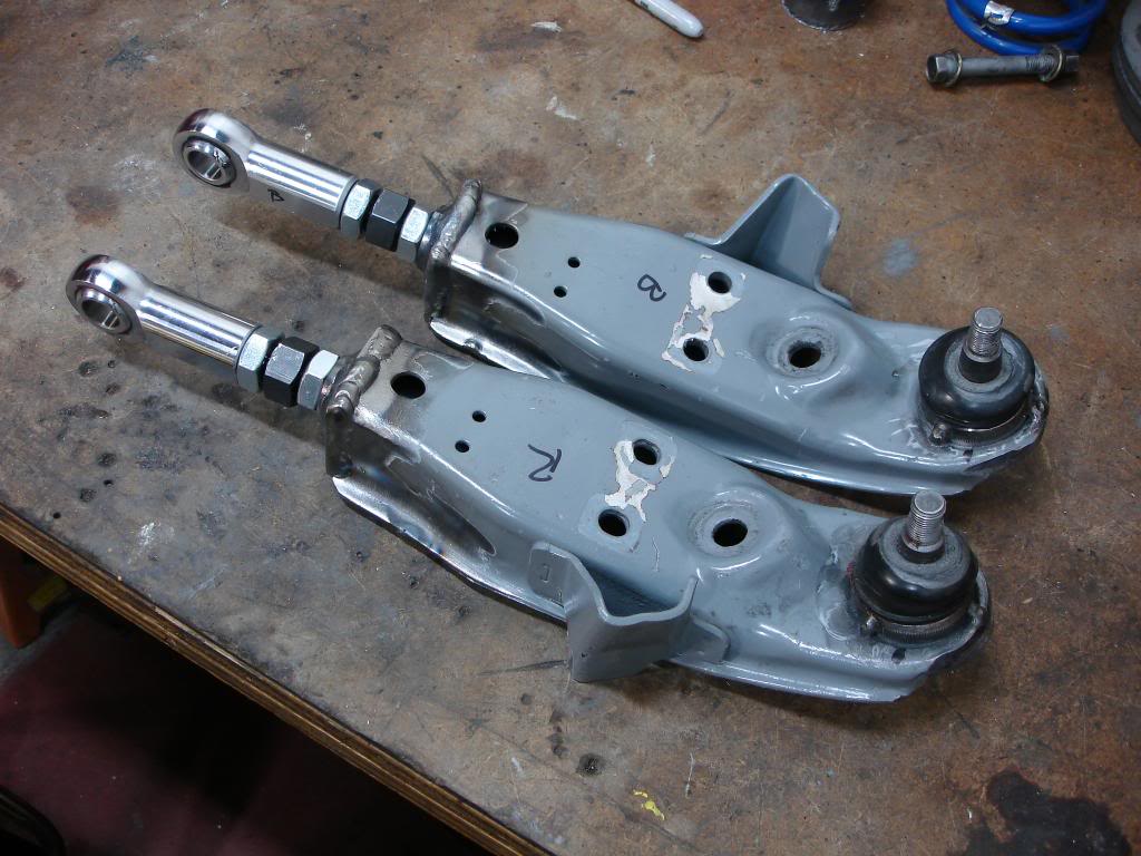
So just got started on the front lower control arms. These will be adjustable for length to make up for the loss of track width caused by using 2" spacers under the struts. They will adjust from the stock length to around 14" safely. I'm thinking that I will need about 1/2 inch tops. This will be another way to get negative camber.
The stock arms have 1/2 spherical bearings at the chassis mount. Other mods include some clearancing in the ball joint end of the arm and the ball joints have been tack welded into place. Laying next to them are the new parts.

Here is what I will use the make the arms adjustable - QA1 5/8 female RH rod end, double ended 5/8 adjuster with RH and LH threads and a 5/8 LH tube end.

We are committed now!

All welded up

overall........
I know I've said this before but everything is so awesome! I was thinking about that very mod for my control arms until I decided to swap to the FC subframe. Can't wait to see how this thing does on a track.

Nice job on the control arms! I commend you for your fabrication skills! Do you have a shot of the control arms showing the welded section where the new inner section is welded to the control arm? Like, say, 90 degrees counterclockwise from the one shot you have of the finished product? Curious to see how that looks.
Thread Starter
Joined: Nov 2006
Posts: 1,578
Likes: 288
From: Parkville, Mo
Thanks guys! You all are too generous with the compliments. I have had the good fortune to spend allot time around several experienced fabricators and racers. So monkey see monkey do!
Yes, I will get some more detailed images of the control arms. I have more work to do on them. The threaded tube ends are welded into .125" plates that I used to cap the ends of the control arms.
Yes, I will get some more detailed images of the control arms. I have more work to do on them. The threaded tube ends are welded into .125" plates that I used to cap the ends of the control arms.
Thread Starter
Joined: Nov 2006
Posts: 1,578
Likes: 288
From: Parkville, Mo


Thread Starter
Joined: Nov 2006
Posts: 1,578
Likes: 288
From: Parkville, Mo
Front Suspension and Brakes
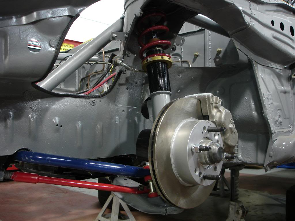
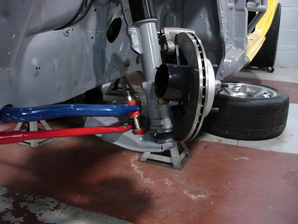
I "think" I have just completed the final assembly on the front brakes and suspension. I now have the adjustable lower control arms installed, the 6" x 500lb springs and I have simplified the brake lines.
Here is the battery I installed. It weighs 13lbs and was pretty inexpensive.
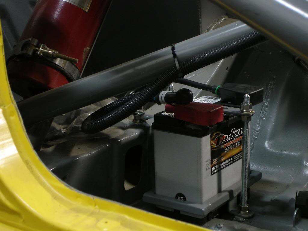


Here is the battery I installed. It weighs 13lbs and was pretty inexpensive.

Thread Starter
Joined: Nov 2006
Posts: 1,578
Likes: 288
From: Parkville, Mo
A milestone was reached on Wednesday.....brake fluid was put in the master cylinders for the first time in 5 years. I fixed all the leaks and will bleed the system in a few days. Heres hoping the master cylinders I selected for the car have good pedal feel.
On to even better news, the 85 13B that have to work with appears to be a diamond in the rough. The engine was running well when it came in the shop but you never know until you start the disassembly process. So far the rear housing is fantastic and step wear is minimal on the rear and center iron. Looks like I have a great starting point for the street port engine I have planned.
On to even better news, the 85 13B that have to work with appears to be a diamond in the rough. The engine was running well when it came in the shop but you never know until you start the disassembly process. So far the rear housing is fantastic and step wear is minimal on the rear and center iron. Looks like I have a great starting point for the street port engine I have planned.
Thread Starter
Joined: Nov 2006
Posts: 1,578
Likes: 288
From: Parkville, Mo
I have my engine disassembled and I have started the cleaning process. The rear rotor housing is good but the front housing has flaking so I will be buying new ones from Mazdaspeed. Thank God for Mazda's racing support. If you are building or racing a Mazda make sure you register with them, the savings are significant.
I spent the day drilling and taping the heater, water temp and oil pressure holes on the rear iron so I can seal them up. I'll pull temps and pressures from other areas on the engine. Next I'll begin the porting process.
I just about have the brakes bled. I had a -3 line from All Star products leak so that set me back a little. I have the replacement line in and will work on getting the rest of the air out of the system.
Pickup my Lexan hatch and rear quarter windows from KC Raceware. Charlie has a quartz oven that allows him to form lexan sheet to match the shape of any piece of automotive glass.
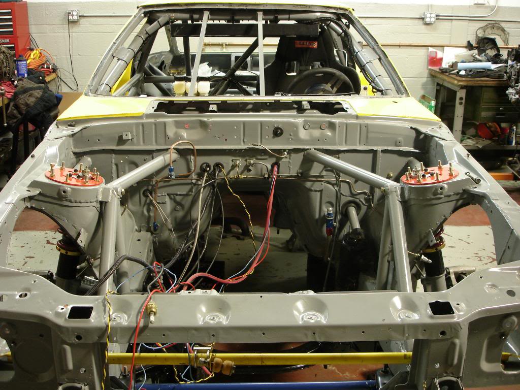
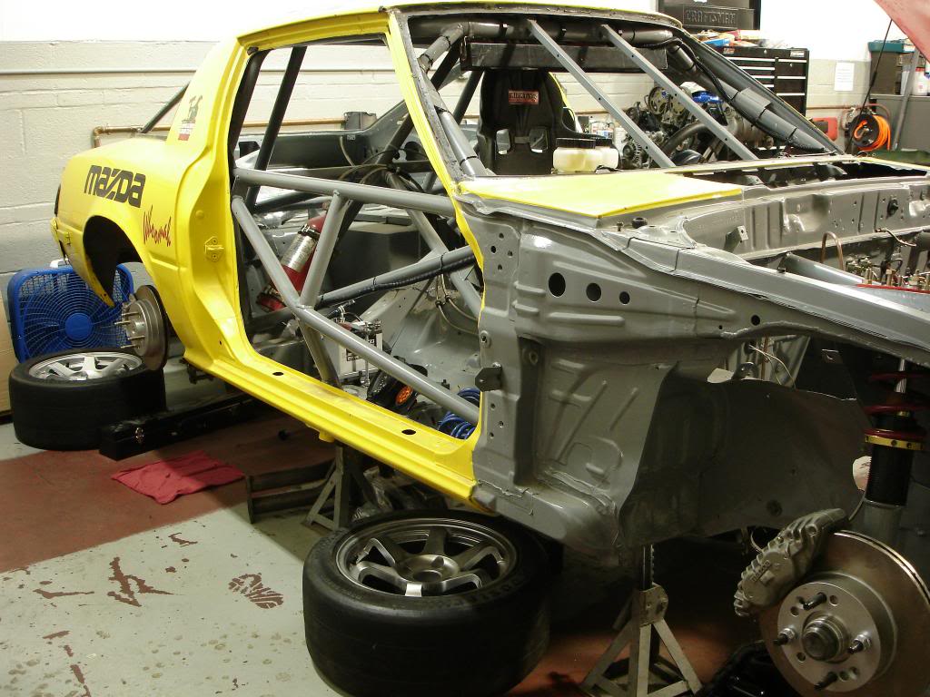
Here are some overall views of the car in my stall at Santa Fe Garage

I spent the day drilling and taping the heater, water temp and oil pressure holes on the rear iron so I can seal them up. I'll pull temps and pressures from other areas on the engine. Next I'll begin the porting process.
I just about have the brakes bled. I had a -3 line from All Star products leak so that set me back a little. I have the replacement line in and will work on getting the rest of the air out of the system.
Pickup my Lexan hatch and rear quarter windows from KC Raceware. Charlie has a quartz oven that allows him to form lexan sheet to match the shape of any piece of automotive glass.
Here are some overall views of the car in my stall at Santa Fe Garage


Last edited by mustanghammer; Mar 1, 2014 at 10:23 PM. Reason: add pictures

Joined: Mar 2001
Posts: 31,855
Likes: 3,243
From: https://www2.mazda.com/en/100th/
The Ground Control camber plates on my racecar had seen better days. 10+ years of curb hopping and off track excursions had bent both of them and caused one of them to crack. Replacing them with another set from Ground Control really wouldn't work because the car will now have stiffer springs, strut towers that are not going to flex and the plates will be mounted on the top of the tower. I am mounting the plates to the top of the tower to make spring/strut changes easier.
David Long at Santa Fe Garage (Santa Fe Garage Automotive Services in Independence, MO) copied the ground control plates in 5/16" cold rolled steel using a mill/drill. I then finished them on a belt sander and powder coated them. I also doubled the number of studs holding them to the car.
David Long at Santa Fe Garage (Santa Fe Garage Automotive Services in Independence, MO) copied the ground control plates in 5/16" cold rolled steel using a mill/drill. I then finished them on a belt sander and powder coated them. I also doubled the number of studs holding them to the car.
we've done steel plates for a long time now, and it'll be interesting to see what the extra bolts do. we run normal bolts, and the plates bend, so our fix was to stack 2 half inch plates
