y-pipe revised 2.0
 10-31-06, 10:32 PM
#1
almost done
Thread Starter
Join Date: Dec 2001
Location: 250 HZ
Posts: 1,049
Likes: 0
Received 0 Likes
on
0 Posts
y-pipe revised 2.0
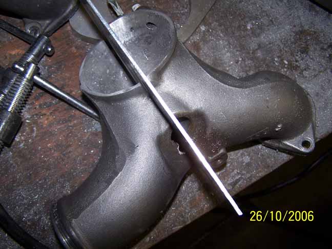
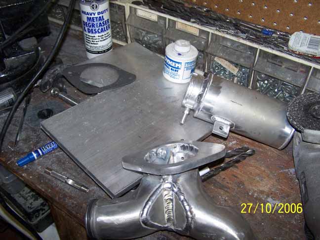
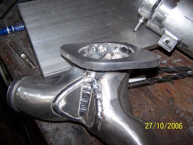
first mod was to put flanges instead of the coupling.
https://www.rx7club.com/3rd-generation-specific-1993-2002-16/modified-y-pipe-562651/
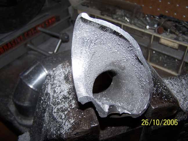
second mod was to add a divider in the middle of the y-pipe to help with flow.
the results is that the second turbo kicks a little harder and transition is a lot more quiet, just posting this in case someone else was interested about this mod that was seen in a old RX-7 magazine.
https://www.rx7club.com/3rd-generation-specific-1993-2002-16/modified-y-pipe-562651/
second mod was to add a divider in the middle of the y-pipe to help with flow.
the results is that the second turbo kicks a little harder and transition is a lot more quiet, just posting this in case someone else was interested about this mod that was seen in a old RX-7 magazine.


Trending Topics
11-01-06, 07:18 AM
#9
Great fab work, but doesn't air take the path of least resistance? If this is true what is stopping it from flowing right over the top of the divider and going toward the secondary just like before? Just wondering, and like I said GREAT work.
thanks,
-josh
thanks,
-josh
11-01-06, 07:38 AM
#10
almost done
Thread Starter
Join Date: Dec 2001
Location: 250 HZ
Posts: 1,049
Likes: 0
Received 0 Likes
on
0 Posts
thanks^
"what is stopping it from flowing right over the top of the divider and going toward the secondary just like before?"
^ the only time that would happen is when you let off the gas and the TB closes.
"what is stopping it from flowing right over the top of the divider and going toward the secondary just like before?"
^ the only time that would happen is when you let off the gas and the TB closes.
11-01-06, 09:49 AM
#12
Rotary Enthusiast
iTrader: (5)
Join Date: Mar 2005
Location: Boxford, MA
Posts: 791
Likes: 0
Received 0 Likes
on
0 Posts
haha nice illustrations. I suspect that what you are showing above is a nearly instantaneous transient effect and once the pressure builds up slightly the difference is negligible, but it's an interesting idea. Cool that you seem to be getting better secondary response, but isn't the goal by what your showing above to improve primary response?
11-01-06, 10:15 AM
#13
almost done
Thread Starter
Join Date: Dec 2001
Location: 250 HZ
Posts: 1,049
Likes: 0
Received 0 Likes
on
0 Posts
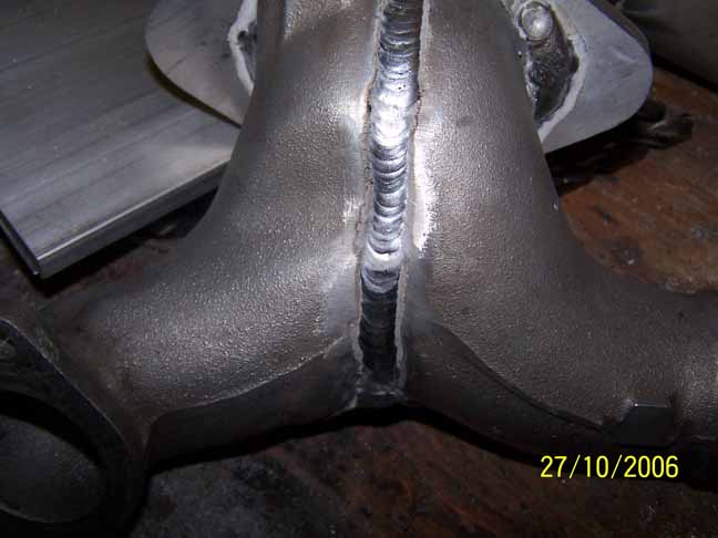
recon fd - with aluminum i just fabricate tack weld and take to my friends shop the power at my house sucks the power breaker goes out when i use my mig welder on high power.
Maximum - its for both but primary response was not that noticeable and i got lazy on the animation.
Maximum - its for both but primary response was not that noticeable and i got lazy on the animation.
11-04-06, 09:11 AM
#16
Full Member
iTrader: (1)
Join Date: Sep 2004
Location: NY
Posts: 234
Likes: 0
Received 0 Likes
on
0 Posts
Understand the idea, but have spent to much time working on a flow bench not to ask. Have you flowed the pipe before and after?
Very nice clean work. Clearly you know your way around a GTAW welder.
Very nice clean work. Clearly you know your way around a GTAW welder.
 pretty please with a cherry on top HA HA
11-05-06, 02:11 AM
pretty please with a cherry on top HA HA
11-05-06, 02:11 AM
#18
NAN777

Join Date: Oct 2005
Location: Malaysia
Posts: 369
Likes: 0
Received 0 Likes
on
0 Posts
personally thinking... that's a good idea. but think of it this way.. if the turbo start kicking in... the air will need to fill up the 1st chamber.. once they got to the top pipe... the air needs to be filled backwards toward to 2nd chamber and also the main pipe towards the IC.
due to the air travel, it need longer time to get to full boost...
if the Y pipe was not partitioned, it will immediately filled up the 1st chamber + 2nd chamber then the air flows toward the IC pipe and toward the IC....
between these 2, theorotically, partitioning it might delay the full boost by a few milli seconds... not noticeble. if you have a one way valve to block it from flowing towards the 2nd chamber... then it'll be faster... when the 2nd boost comes in.. it'll be instantaneous quick response...
just my 2 cents.
08-12-07, 08:07 PM
#20
08-13-07, 02:32 AM
#22
Glug Glug Glug Burp
Join Date: Jan 2002
Location: Scott AFB, IL
Posts: 3,819
Likes: 0
Received 0 Likes
on
0 Posts
It is great to see however, I like to think that the original engineers would have done similar had it really been necessary or beneficial.
Regardless, nice fab work. Next step should be testing it against a stock piece to prove the efforts' worth.
08-13-07, 08:38 AM
#23
Banned. I got OWNED!!!
Join Date: Jul 2004
Location: next to the polishing wheel!!!
Posts: 1,179
Likes: 0
Received 1 Like
on
1 Post
I also put a flange on stock y pipes and I mod the late model ones.I put five bolts in them instead of two .No warping or leaks .I also remove the blowoff nipple and reshape that area .