
Want to make SS pressure and vac chambers, need advice


Want to make SS pressure and vac chambers, need advice
So I had this idea for a while now. I want to make my own Stainless Steel Vacuum and Pressure chambers for the sequential twins (my friend has a company that makes professional kitchen equipment out of SS and can pretty much make anything I ask him to)
Now I understand that some of you might think this is completely pointless considering the stock plastic chambers are somewhat durable and good replacements are easily and cheaply found. And I partially agree with you there, even more considering my stock plastic ones work just fine. And some of you might say �just go non-sequential��
However, the reasons I would do this:
- Love stainless steel
- Hate plastic parts in the engine bay
- Locating them somewhere else to clean up the look of the engine
- Reliability of SS over plastic
- Want to keep sequential twins (maybe BNR�s down the road)
- Have too much time on my hands?
- My friend wouldn�t charge me anything so I would be getting them for free
So I did a search but I found no thread about this. Please let me know if someone has done this before.
So my question is: would the SS versions have to have the exact same volume as the stock plastic ones? If yes, could I use for example water and fill each chamber up full and then pour the water out into something else and exactly measure the volume.
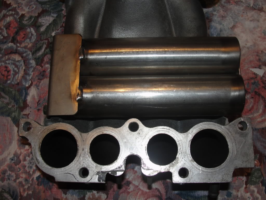
I will be going simplified seq so I will have more space under the UIM so my plan would be to place both chambers under the UIM, and shape the new chambers in a cylindrical or cube shape�depending what works better.
Any potential drawbacks to this idea?
And advice is appreciated! Thanks
Now I understand that some of you might think this is completely pointless considering the stock plastic chambers are somewhat durable and good replacements are easily and cheaply found. And I partially agree with you there, even more considering my stock plastic ones work just fine. And some of you might say �just go non-sequential��
However, the reasons I would do this:
- Love stainless steel
- Hate plastic parts in the engine bay
- Locating them somewhere else to clean up the look of the engine
- Reliability of SS over plastic
- Want to keep sequential twins (maybe BNR�s down the road)
- Have too much time on my hands?
- My friend wouldn�t charge me anything so I would be getting them for free
So I did a search but I found no thread about this. Please let me know if someone has done this before.
So my question is: would the SS versions have to have the exact same volume as the stock plastic ones? If yes, could I use for example water and fill each chamber up full and then pour the water out into something else and exactly measure the volume.
I will be going simplified seq so I will have more space under the UIM so my plan would be to place both chambers under the UIM, and shape the new chambers in a cylindrical or cube shape�depending what works better.
Any potential drawbacks to this idea?
And advice is appreciated! Thanks

I can see no drawbacks to this.
It would be wise to keep the volume the same or similar just because running out of vac or pressure would cause a loss of boost.
Bonus points if you find a clean way to integrate a pressure limiting valve on the pressure tank so that it never exceeds a pressure number that will lock up the solenoids. Otherwise an inline ball-spring boost controller on the feed line to the pressure tank will take care of that.

TitaniumTT used to be on this forum, now located on the other forum. He had built the chambers from aluminum if I remember correctly.
Cool project though, would be interesting if coupled with some Azknights solenoids.
Vince
Cool project though, would be interesting if coupled with some Azknights solenoids.
Vince
Thanks guys. I'll try to find the aluminum ones that TitaniumTT made.
If I decided to add a pressure relief valve to the SS pressure chamber what would I set the opening pressure at, at stock boost levels for example? or in other words what is the average or maximum pressure that accumulates inside the pressure chamber?
Bonus points if you find a clean way to integrate a pressure limiting valve on the pressure tank so that it never exceeds a pressure number that will lock up the solenoids. Otherwise an inline ball-spring boost controller on the feed line to the pressure tank will take care of that.
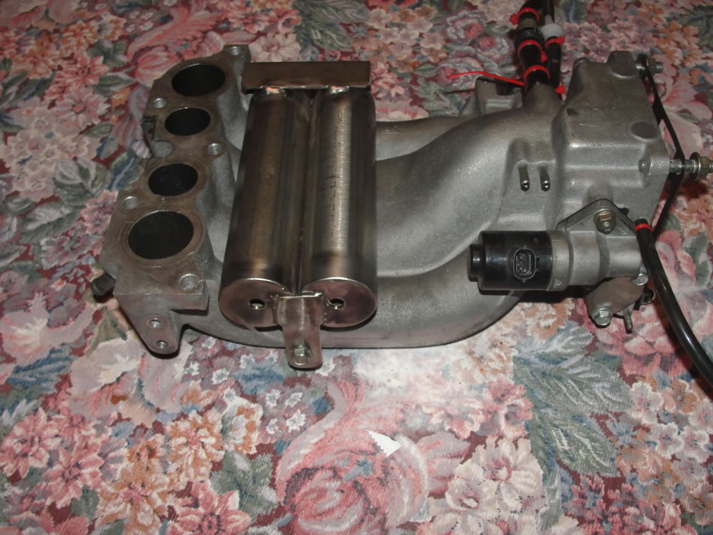
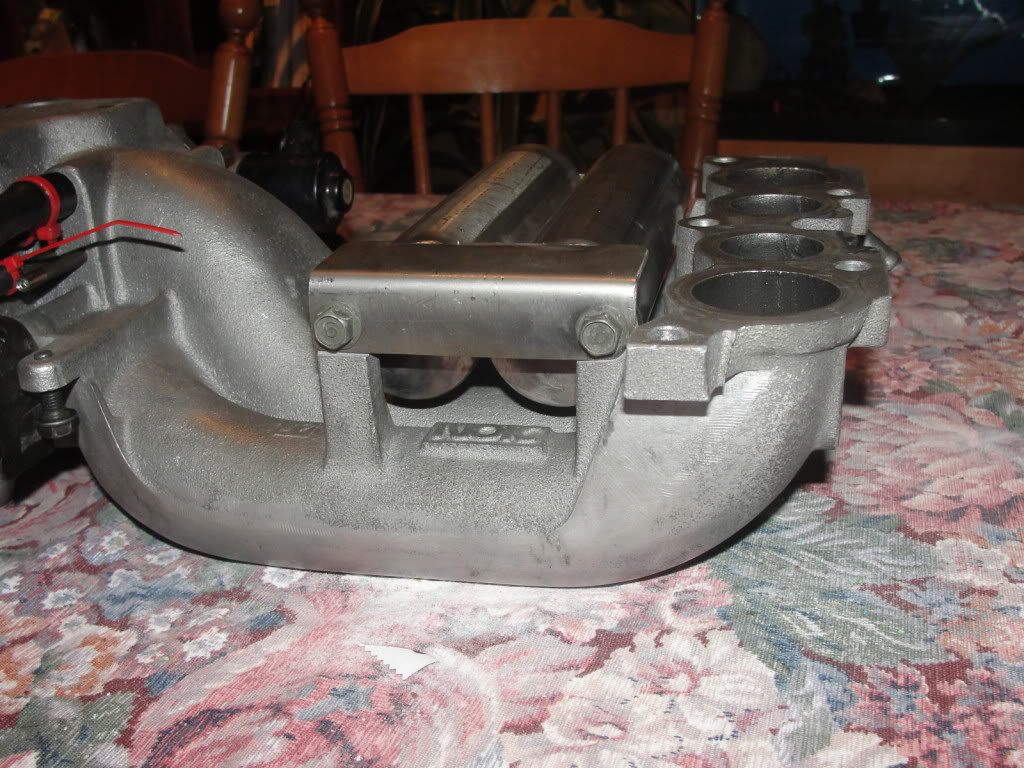
This is my setup and use it for +2500km and work great! I will try to take picture of it installed on the car!
The maximum pressure that the tank accumulate is the same as your boost is set! For a stock setup is 10psi! I pressure test both at 25 psi for 24hour and still hold on!
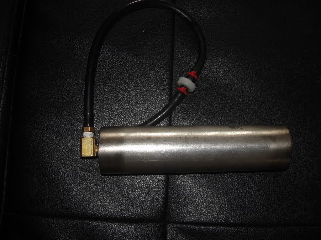
The maximum pressure that the tank accumulate is the same as your boost is set! For a stock setup is 10psi! I pressure test both at 25 psi for 24hour and still hold on!


Trending Topics

Erix thank you very much for showing us your set up.
I'm glad I'm not the only one who would want to do this.
And yes please show us a photo of the UIM installed on the engine
I'm glad I'm not the only one who would want to do this.
And yes please show us a photo of the UIM installed on the engine


The system stores full max boost pressure, which for a stock car is 10psi. As the solenoids age, they can stick under pressure. This is made worse when the car is modified to develop 10+ psi of boost. (Vacuum on the other hand, does not tend to stick solenoids, and is limited by the engine's maximum vacuum.) Enter the pressure regulator - set it to limit the chamber pressure to 8 or 10psi, and now the solenoids and turbo function will be immune to increased boost. (Technically you may need to adjust it as you adjust boost, since the regulator is technically regulating the difference between the pressure source and pressure tank). That's the theory and it tends to work pretty well.
David


For sure it will not fit with the AWS solenoid but at least i want to know if it will fit with a block off plate!

Junior Member
Joined: Jan 2013
Posts: 22
Likes: 0
From: MD
It would be very easy to take one of these and remove the petcock and replace with a plug and replace the hose barbs with your desired size. As long as it is not baffled it would work fine. Just search for go kart catch cans. The dimensions for this one are 3-1/8" long and 2-1/4 in diameter.

You could even replace the petcock with and adjustable pressure relief valve to set your desired max psi.
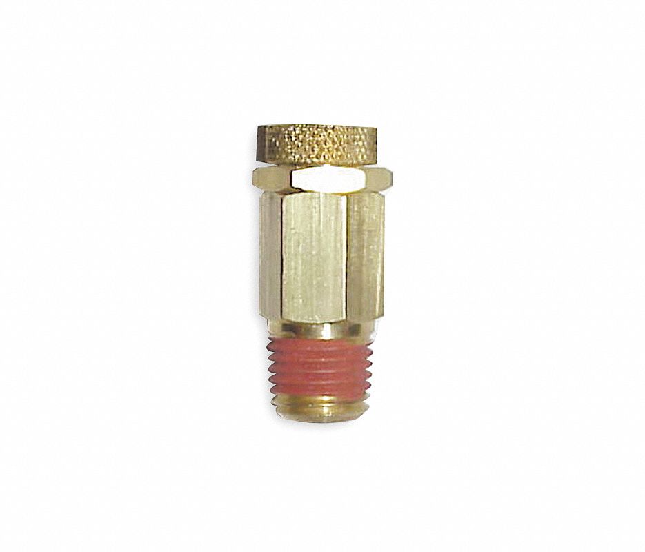
http://www.grainger.com/product/CDI-...763?s_pp=false
You could even replace the petcock with and adjustable pressure relief valve to set your desired max psi.
http://www.grainger.com/product/CDI-...763?s_pp=false

Thread
Thread Starter
Forum
Replies
Last Post
trickster
2nd Generation Specific (1986-1992)
25
Jul 1, 2023 04:40 PM
turbo-minivan
General Rotary Tech Support
69
Feb 4, 2016 12:29 AM