
Improve cooling with laminar flow air channels

Thread Starter
Spinning Dorito
iTrader: (11)
Joined: Dec 2010
Posts: 405
Likes: 0
From: Boulder, Colorado
I have been doing some reading on laminar flow and how it affects air speed and general channeling through a passage. Now I am very interested to see what the general public thinks as far as this goes. I think it could be a plausible way to increase air flow and efficiency. Directly channeled to the radiator, intercooler, oil cooler(s) etc. There would be a dense cluster of tubes or straws that could be lightweight and cut to angle and length.
Now the radiator is already designed to create laminar flow since air travels through the fins air flow gets directed in a more linear path. Now the problem is the air coming through the front of the vehicles openings. This air is turbulent.

The image in the bottor is a very crude but efficient example.


In similar ways that a catalytic converter works, for the exception of high density clusters.

If this could prove the a cost effective way of improving flow I might toy with the idea.
Any thought and input greatly appreciated
Now the radiator is already designed to create laminar flow since air travels through the fins air flow gets directed in a more linear path. Now the problem is the air coming through the front of the vehicles openings. This air is turbulent.
The image in the bottor is a very crude but efficient example.
In similar ways that a catalytic converter works, for the exception of high density clusters.
If this could prove the a cost effective way of improving flow I might toy with the idea.
Any thought and input greatly appreciated
I'm ignorant non the subject, but does the length of the "straws pack" affect the airflow improvement? Is there also any relationship between the front surface of the straws pack and its length?


Small brain government worker here. Neat concept. My first thought is that this works in airplanes and catalytic converters. But you have to consider the application. Bugs, dirt, seeds, leaves, and even the occasional slow rodent also enter through the nose of the car. And those appear to be pretty small channels.
Temp differential and time of contact also play in to cooling. Seems like you want high pressure in front of the radiator and low pressure after it. Maybe the best place to improve flow this way is behind the radiator somehow. ??
Temp differential and time of contact also play in to cooling. Seems like you want high pressure in front of the radiator and low pressure after it. Maybe the best place to improve flow this way is behind the radiator somehow. ??
How about the air before your laminar air flow apparatus? Point is that somewhere you will have turbulence, I don't suspect it matters much if that turbulence is inside the mouth of your bumper or just in front of your bumper.
Certainly not an aerodynamicist, but thinking about it, I've never known a catalytic converter or even an intercooler core (which has a similar matrix) to improve flow... usually you get some pressure drop/restriction. I'm not sure why the air inside each of those little tubes isn't just just a miniaturized version of what's in the big open tube.
Now the radiator is already designed to create laminar flow since air travels through the fins air flow gets directed in a more linear path. Now the problem is the air coming through the front of the vehicles openings. This air is turbulent.
The air traveling through the heat exchanger fins is not laminar flow, but turbulent.
The heat exchanger fins are punched in a way to increase surface area and promote turbulent flow to increase heat transfer at a slight cost to heat exchange medium (air) velocity through the core.
A properly designed duct is indeed one that not only retains air velocity within the duct, but distributes the air evenly over the core. The duct should also help retain air that has entered the duct from being rejected by the face of the heat exchanger.
There is definitely modeling that goes into proper ducting- you can check out the old NACA/NASA reports on it from when airplane engines/heat exchangers became streamlined to get ideas on what works best.
I think your idea has merit in at least the example of a forward facing duct opening leading to a severely angled heat exchanger core. This was found to be an inefficient design in the NACA reports, but often a desirable layout in our cars due to packaging and keeping a thin heat exchanger core cross section due to the relatively low air velocities available.
While you are looking up the NACA ducting reports check into foamed carbon heat exchangers and nano-rod coolants. If you want to push the envelope on cooling you might want to start with the cutting edge heat exchangers/media and their requirements before even messing with traditional exchangers/media.
Part of the problem bringing on the new tech is the traditional ducting/layout/low pressure fans (at least with the foam carbon heat exchangers).

Trending Topics
From the patent-
A radiator utilizes laminar flow to more efficiently cool a liquid coursing through the radiator. The radiator spaces a pair of cores a sufficient distance apart to produce laminar flow between the cores.
Looking at that it seems most aftermarket performance radiators use this concept.
A 2 row radiator and 3 row radiator most certainly have heat exchangers spaced closely to each other within the radiator construct that air traveling exiting the 1st row enters the 2nd row in laminar flow.
You balance air inlet/outlet pressure drop, cooling capacity and fan space available.
Sometimes its better to use a thinner 1 row core and a thicker fan to move more air through the radiator than a thick core and a thin fan.
It does not matter if the flow is laminar or turbulent before the heat exchanger it only matters what is in the boundary layer.
That may be true in the case of a duct that distributes the air correctly to the core (as it should), but if you look at the NACA reports when air in the duct strikes the core at an obtuse angle the core face presents a greater pressure drop.
This is where a mass of bent straws may help in an otherwise compromised duct layout.
This is worth mentioning because it is exactly the layout the FD stock radiator has and both the radiator and intercooler have in the popular V-mount layout.
The old aftermarket SMIC duct/intercooler by contrast has NACA approved ducting layout.
That is not to say the V-mount doesn't work great. It does by virtue of larger heat exchanger cores, room for larger radiator fans and greater ease of air exhaust through the IC core. The V-mount inlet ducting could be further improved if there was cause.

Hey guys,
Just my observation here. I do not believe the term Laminar flow is really understood.
The abilities of laminar flow are the same in air and in slower moving fluid.
Laminar flow is the ability for the air to adhere to the surface. For example in a wing,
the top of the wing is curved and the bottom is relatively flat. Laminar flow is the definition
of why the air on top of the wing is adhering to the entire curved surface.
Once you exceed the critical angle of attack (like a plane pitching up too much)
the air will no longer be able to adhere to the entire surface of the upper part of the wing.
This is a stall, where the air separates from the wing and turbulent air will be behind the separation of course.
Take a back side of a spoon under your slow running faucet. As you change the angles
the water will still follow the curved shape of the spoon.
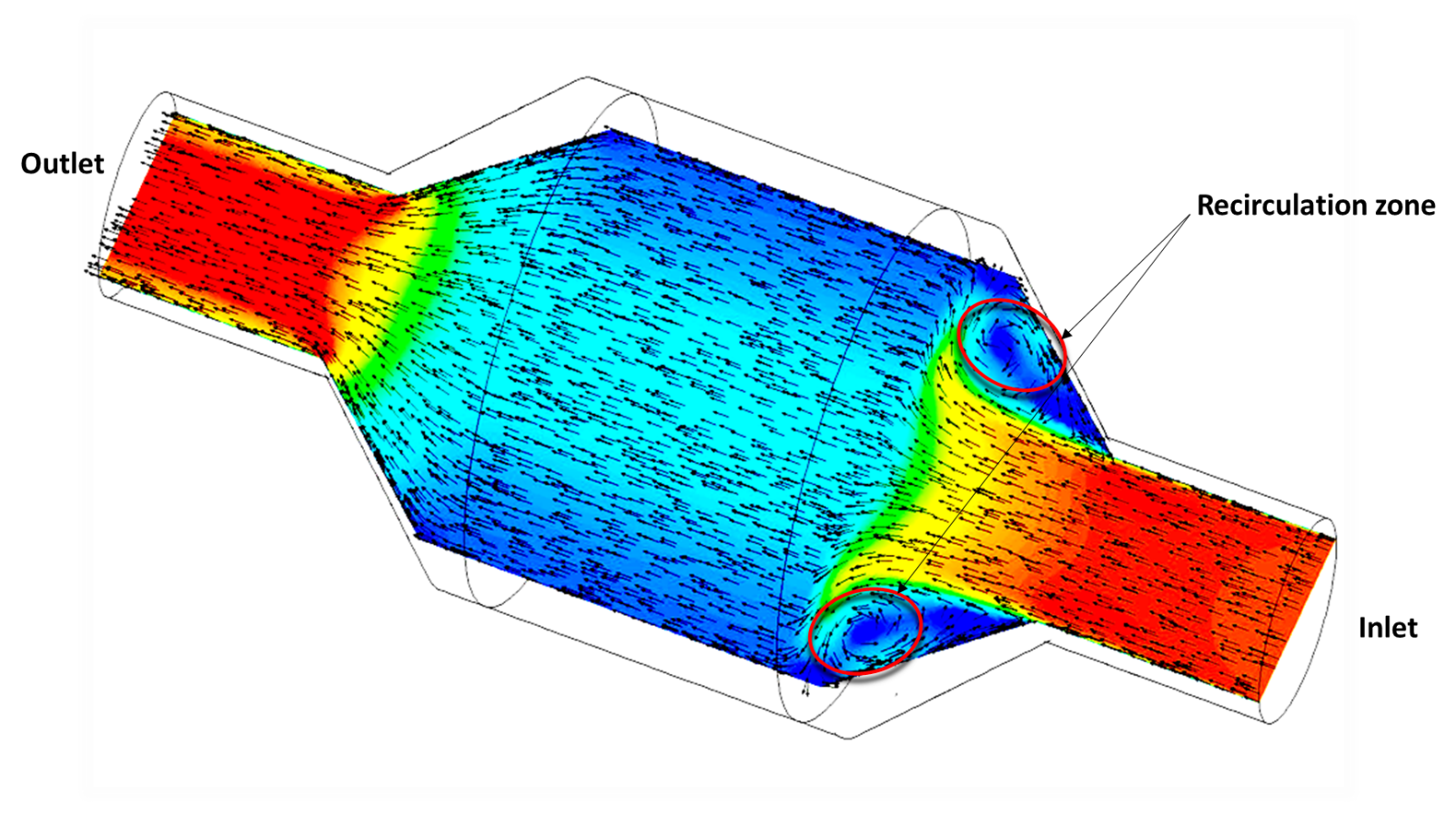
The cat converter shown should be described as demonstrating that
utilizing better aerodynamics( ie. laminar flow)
in the outer casing, that the exhaust flow(air) will be able to adhere to the inner walls
and allow more exhaust to be distributed more evenly throughout the cell structure.
Not just focused in the middle as the other model shows.
Hope this makes sense.
That being said, Blue TII has it nailed..
One last thing to consider, and may have been indicated by Blue TII, make a radiator and or
intercooler that its airflow is in the best angle for the mounting position.
For example, if the radiator is mounted in a 30degree angle, have the rows facing
horizontal to the airflow in which is cooling.
Just my observation here. I do not believe the term Laminar flow is really understood.
The abilities of laminar flow are the same in air and in slower moving fluid.
Laminar flow is the ability for the air to adhere to the surface. For example in a wing,
the top of the wing is curved and the bottom is relatively flat. Laminar flow is the definition
of why the air on top of the wing is adhering to the entire curved surface.
Once you exceed the critical angle of attack (like a plane pitching up too much)
the air will no longer be able to adhere to the entire surface of the upper part of the wing.
This is a stall, where the air separates from the wing and turbulent air will be behind the separation of course.
Take a back side of a spoon under your slow running faucet. As you change the angles
the water will still follow the curved shape of the spoon.
The cat converter shown should be described as demonstrating that
utilizing better aerodynamics( ie. laminar flow)
in the outer casing, that the exhaust flow(air) will be able to adhere to the inner walls
and allow more exhaust to be distributed more evenly throughout the cell structure.
Not just focused in the middle as the other model shows.
Hope this makes sense.
That being said, Blue TII has it nailed..
One last thing to consider, and may have been indicated by Blue TII, make a radiator and or
intercooler that its airflow is in the best angle for the mounting position.
For example, if the radiator is mounted in a 30degree angle, have the rows facing
horizontal to the airflow in which is cooling.

Thread
Thread Starter
Forum
Replies
Last Post
Jeff20B
1st Generation Specific (1979-1985)
73
Sep 16, 2018 07:16 PM
[For Sale] Scratch & Dent, Used, and Open-Box Sale!
SakeBomb Garage
Vendor Classifieds
5
Aug 9, 2018 05:54 PM
ZaqAtaq
New Member RX-7 Technical
2
Sep 5, 2015 08:57 PM