
David Hayes DIY LED Taillight Modification


You can always adjust up but then we will have criticism from those on this thread that complain they are too bright

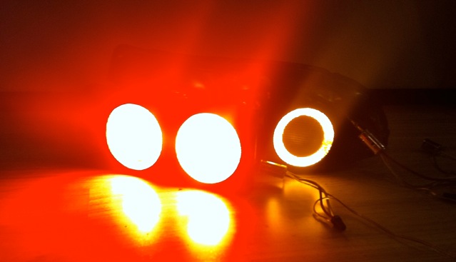
Happy to do this when we get a little sun. Iv'e already seen them in FL on M104-AMG's in the sun and they look great. But that is opinion. The proof is in the light output testing numbers and these test slightly brighter than the superbright.com LEDs which are 150% brighter than stock and this is with turning them down.
You can always adjust up but then we will have criticism from those on this thread that complain they are too bright
You can always adjust up but then we will have criticism from those on this thread that complain they are too bright
That is a good idea but beyond my capabilities. If someone knows how to wire this up I'd try it. The dimmer units I am using have an internal adjustment so the relay would need to lower power at night. They do make externally dimmable drivers too which might be better suited to the task. Any electrical experts around?
Last edited by mar3; Nov 13, 2011 at 05:27 PM. Reason: Killed quote since reply was back-to-back to post in question...

David, I'm doing it backwards.... damn. lol. I'll have to pull it apart I guess. Appreciate the help once again. I'll be on hold for a few days while I order a dremel circle cutter (apparently home depot and lowes dont carry circle cutter guides from what I've found )

Dang I thought my led retrofit was a mess lol. I might of missed it but I didn't see any regulators on the 80mm and 75mm rings. I would strongly suggest adding some Sharp PQ12RD21J00H regulators to them nothing kills leds faster then unstable voltage. They only have a dropout voltage of .5V it's the lowest I have seen. The ones from radio shack have I think 2V dropout so they don't regulate the voltage the whole time.
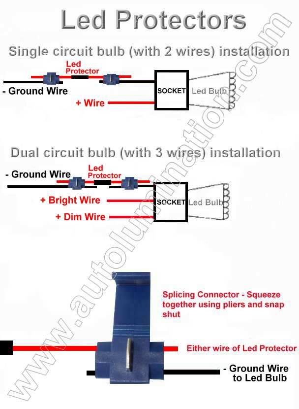
^ That is a good idea and anything to protect the LEDs is welcome. Do you think these will work? If so they are easy to install as you'd just clip these in on the ground wire:
http://autolumination.com/equalizers.htm
Led Protector
Designed to help protect any led bulb from power and voltage surges
Got a vehicle that eats leds??
Helps protects LEDS from premature failure - Designed to works with any 12 volt led bulb
Common causes of Premature LED Failure
Switching on the ignition & starting the engine while the leds are switched on.
Changing or disconnecting the battery while the leds are switched on.
Charging the battery with an auxiliary battery charger, or revving the engine hard with a weak or dead battery while the leds are switched on.
Using jumper cables while the leds switched on.
Excessive AC voltage due to damaged diodes in the alternator.
High system or circuit voltage.
Voltage surges caused from switching on and off amplifiers or other peripheral add on devices that use a lot of power.
Faulty or out-of spec. voltage regulators.
So Mr. BryanDowns, how is it going with the project? Any updates?
Also, I just noticed superbrightleds.com is running a 5% off banner on the forum. Use code RE753 when ordering for the discount.
Also, I just noticed superbrightleds.com is running a 5% off banner on the forum. Use code RE753 when ordering for the discount.
Still waiting on USPS or UPS (or whomever my circle cutter shipped through) I'm hopeful that today is the day it shows up at my house
Missing Pics
Back in FL for Thanksgiving. Hope everyone has a safe and happy holiday and "War Eagle"!
On topic, here are the missing pics from the beginning of the thread. Mods, when merging the thread back together, will you please fix the broken links?
Pics for Post #2:
Parking Lights On:
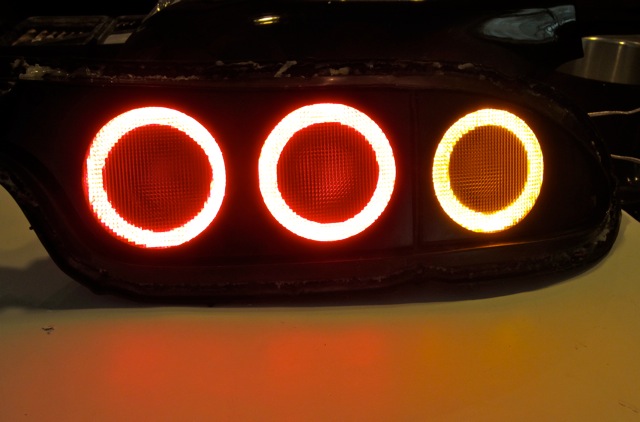
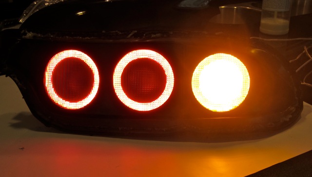
Parking Lights With Turn Signal On:
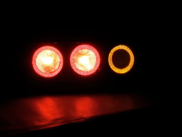
Parking Lights With Brakes On:
On topic, here are the missing pics from the beginning of the thread. Mods, when merging the thread back together, will you please fix the broken links?
Pics for Post #2:
Parking Lights On:
Parking Lights With Turn Signal On:
Parking Lights With Brakes On:
Missing Pics
Post #3
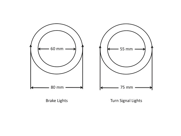
Here are the dimensions for the acrylic rings. The brake rings are slightly larger than the turn signal rings due to the difference in sizes of the 99 spec conversions:
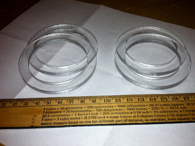
I used a Dremel circle cutter, which worked great, to make these:
http://www.google.com/products/catal...wAA#ps-sellers
Here are pics of the acrylic rings I fabricated with the Dremel:
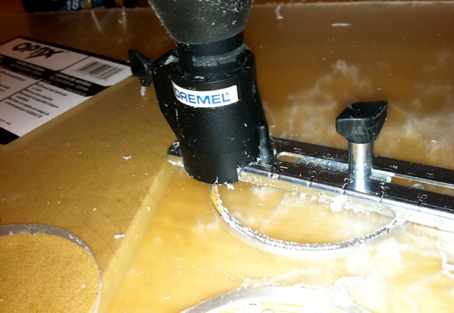
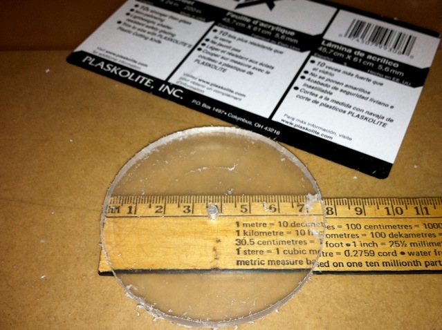
** A note on cutting the acrylic rings **
Cut the outer circle first and then the inner circle. Once you've cut the outer circle you can then cut the inner circle by simply holding and rotating the acrylic. Be careful with the last bit of cut as there is nothing to support the circle. Try one and you'll see what I mean.
The Dremel drill bit has an outer and inner edge so when you make a circle, you will need to account for the thickness of the bit. For outer circle cuts, set the device so the inside of the bit edge is at the desired dimension. So for 80 mm rings, set the inside of the bit at 80 mm. For inside circle cuts, set the outside of the bit to the desired dimension.
You can use the bit to help smooth out an outside circle cut by simply rotating the circle still on the Dremel after you've cut the circle. By doing this you use the Dremel to clean up the outside edge. I used a Dremel sanding attachment to clean up the inside edges.
Finally, I found it was best to make all Dremel cuts with the acrylic stock material raised up and off of the surface. This gives the Dremel room for the waste cut material to drop below the ring and not get caught up in the circle cut.
Here are the dimensions for the acrylic rings. The brake rings are slightly larger than the turn signal rings due to the difference in sizes of the 99 spec conversions:
I used a Dremel circle cutter, which worked great, to make these:
http://www.google.com/products/catal...wAA#ps-sellers
Here are pics of the acrylic rings I fabricated with the Dremel:
** A note on cutting the acrylic rings **
Cut the outer circle first and then the inner circle. Once you've cut the outer circle you can then cut the inner circle by simply holding and rotating the acrylic. Be careful with the last bit of cut as there is nothing to support the circle. Try one and you'll see what I mean.
The Dremel drill bit has an outer and inner edge so when you make a circle, you will need to account for the thickness of the bit. For outer circle cuts, set the device so the inside of the bit edge is at the desired dimension. So for 80 mm rings, set the inside of the bit at 80 mm. For inside circle cuts, set the outside of the bit to the desired dimension.
You can use the bit to help smooth out an outside circle cut by simply rotating the circle still on the Dremel after you've cut the circle. By doing this you use the Dremel to clean up the outside edge. I used a Dremel sanding attachment to clean up the inside edges.
Finally, I found it was best to make all Dremel cuts with the acrylic stock material raised up and off of the surface. This gives the Dremel room for the waste cut material to drop below the ring and not get caught up in the circle cut.
Missing Pics
Post #4
Fabrication of the LED Units
Tools Required:
- heat gun: to remove the plastic clear lens cover off of the taillight assemblies
- regular screwdriver: to remove the brake and turn signal OEM inside lenses
- metal sheers: for cutting the metal rings and reflectors
- riveter: to hold together the new metal rings and reflectors
- soldering iron: for wiring up the lights
You�ll first need to take apart the taillight assemblies. You do this by removing the 6 screws on the backside of the OEM taillight plastic housing. You then apply heat to the outer back edge of the taillight where the back meets the front clear cover to melt the clear adhesive that holds the front lens cover to the back housing. Take your time and it�s easy. I used a hair dryer because my heat gun was in storage and it took me about 10 minutes of applying heat before I was able to separate the lens from the back housing. Set the front lens cover aside for safekeeping.
With the plastic front lens off, you�ll see the tail lamp has two sections, one comprised of two lights and the other made up of the turn signal. Each of these sections is held on with a single screw (on the upper side of the brake section and the bottom corner of the turn signal) that needs to be removed. Once you have done this, look along the top lip on the right of the brake section and on the left of the turn signal assembly to locate the small tab that secures each section. Use a screwdriver to unclip the tab and pull each section out. There will be some resistance here as each section is also held on with a small amount of clear adhesive.
With this done, you�ll see each taillight is comprised of three light sections, two for the brakes and one for the turn signals. The two new brake LED assemblies are identical 80mm units and the turn signal is a slightly smaller 75 mm size. The size differences correspond to the sizes of the 99 spec brake lights and turn signals.
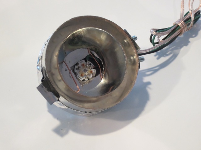
Here are pics of a modified LED brake light unit:
Front of Unit (faces red lens):
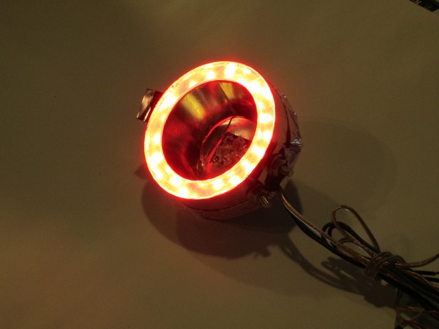
And with the parking lights on:
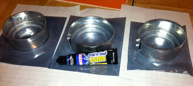
In the middle is a reflector and a high-powered LED circuit mounted component and if you look through the acrylic ring, you can see the 80 and the 60 mm LED rings. For the center reflector, the test unit was glued together using Loctite Stik'N Seal Ultra Universal Adhesive. For the final versions, I also riveted the reflector together. The outer ring in the pic is glued and screwed together but the screws were replaced with rivets as well.
Back of Unit:
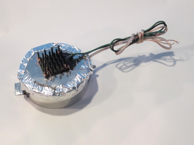
The back of the unit contains the thermal heat sink for the high-powered brake and turn signal LEDs. The heat sink attaches to a back plate (which you will make following the template) with either thermal adhesive glue or with high temp RTV. Either works just fine. I also then used copper wire to attach the heat sink to the back plate for an extra level of security. The silver tape is Home Depot tape that holds the back plate to the round light housings. You could glue this on or use silicone or tape it on. I did both.
Each light assembly is made up of the following:
(1) outside metal ring � see template
(1) inner light metal reflector � see template
(1) metal back plate � see template
(1) acrylic clear ring � 80 mm for the brakes and 75 mm for the turn signals � see templates
(1) high-powered center circuit mounted LED � see parts list
(1) heat sink for high-powered LED � see parts list
(1) 80 mm led ring � red for brakes and amber for turn signal � see parts list
(1) 60 mm led ring � red for brakes and amber for turn signal � see parts list
To fabricate an assembly, use the provided templates to fabricate the acrylic rings and the metal components. See previous pics.
Next, �wrap� the outside metal rings around the two 80 mm acrylic rings and the one 75 mm ring to form the outer housings for the light units. Note there is a separate outer metal housing template for the 75 mm unit. The template for this has one straight side and one curved side. When formed as a circle, the curved side will be placed turn signal lens down resulting in the metal housing being at an angle which will assit in clearing the sides of the OEM back plastic housing. When properly turned, the unit will turn away from the inside wall of the housing. Next, use adhesive and rivets to hold the outer metal rings together. Finally, use adhesive to glue the acrylic rings into the inside front of the metal housings. Here is a pic of the completed outer metal housings and the acrylic rings. The two housings on the left are for the 80 mm brake units and the one on the right is the 75 mm turn signal unit:
Fabrication of the LED Units
Tools Required:
- heat gun: to remove the plastic clear lens cover off of the taillight assemblies
- regular screwdriver: to remove the brake and turn signal OEM inside lenses
- metal sheers: for cutting the metal rings and reflectors
- riveter: to hold together the new metal rings and reflectors
- soldering iron: for wiring up the lights
You�ll first need to take apart the taillight assemblies. You do this by removing the 6 screws on the backside of the OEM taillight plastic housing. You then apply heat to the outer back edge of the taillight where the back meets the front clear cover to melt the clear adhesive that holds the front lens cover to the back housing. Take your time and it�s easy. I used a hair dryer because my heat gun was in storage and it took me about 10 minutes of applying heat before I was able to separate the lens from the back housing. Set the front lens cover aside for safekeeping.
With the plastic front lens off, you�ll see the tail lamp has two sections, one comprised of two lights and the other made up of the turn signal. Each of these sections is held on with a single screw (on the upper side of the brake section and the bottom corner of the turn signal) that needs to be removed. Once you have done this, look along the top lip on the right of the brake section and on the left of the turn signal assembly to locate the small tab that secures each section. Use a screwdriver to unclip the tab and pull each section out. There will be some resistance here as each section is also held on with a small amount of clear adhesive.
With this done, you�ll see each taillight is comprised of three light sections, two for the brakes and one for the turn signals. The two new brake LED assemblies are identical 80mm units and the turn signal is a slightly smaller 75 mm size. The size differences correspond to the sizes of the 99 spec brake lights and turn signals.
Here are pics of a modified LED brake light unit:
Front of Unit (faces red lens):
And with the parking lights on:
In the middle is a reflector and a high-powered LED circuit mounted component and if you look through the acrylic ring, you can see the 80 and the 60 mm LED rings. For the center reflector, the test unit was glued together using Loctite Stik'N Seal Ultra Universal Adhesive. For the final versions, I also riveted the reflector together. The outer ring in the pic is glued and screwed together but the screws were replaced with rivets as well.
Back of Unit:
The back of the unit contains the thermal heat sink for the high-powered brake and turn signal LEDs. The heat sink attaches to a back plate (which you will make following the template) with either thermal adhesive glue or with high temp RTV. Either works just fine. I also then used copper wire to attach the heat sink to the back plate for an extra level of security. The silver tape is Home Depot tape that holds the back plate to the round light housings. You could glue this on or use silicone or tape it on. I did both.
Each light assembly is made up of the following:
(1) outside metal ring � see template
(1) inner light metal reflector � see template
(1) metal back plate � see template
(1) acrylic clear ring � 80 mm for the brakes and 75 mm for the turn signals � see templates
(1) high-powered center circuit mounted LED � see parts list
(1) heat sink for high-powered LED � see parts list
(1) 80 mm led ring � red for brakes and amber for turn signal � see parts list
(1) 60 mm led ring � red for brakes and amber for turn signal � see parts list
To fabricate an assembly, use the provided templates to fabricate the acrylic rings and the metal components. See previous pics.
Next, �wrap� the outside metal rings around the two 80 mm acrylic rings and the one 75 mm ring to form the outer housings for the light units. Note there is a separate outer metal housing template for the 75 mm unit. The template for this has one straight side and one curved side. When formed as a circle, the curved side will be placed turn signal lens down resulting in the metal housing being at an angle which will assit in clearing the sides of the OEM back plastic housing. When properly turned, the unit will turn away from the inside wall of the housing. Next, use adhesive and rivets to hold the outer metal rings together. Finally, use adhesive to glue the acrylic rings into the inside front of the metal housings. Here is a pic of the completed outer metal housings and the acrylic rings. The two housings on the left are for the 80 mm brake units and the one on the right is the 75 mm turn signal unit:
Thanks for the updates David.
I finally got my circle cutter in the mail. My progress will have to wait for a bit; I've been sick and I think my wife will kill me if she finds me cutting acrylic circles in the garage.
Hopefully I'll be feeling better and can get back on this project with some real updates
I finally got my circle cutter in the mail. My progress will have to wait for a bit; I've been sick and I think my wife will kill me if she finds me cutting acrylic circles in the garage.
Hopefully I'll be feeling better and can get back on this project with some real updates
Hey David,
I just noticed what appear to be inner circles in the full assemblies. Is that an optical illusion or is there one? (Or is it part of the brake light LED's that I am still waiting on in the mail?)
I just noticed what appear to be inner circles in the full assemblies. Is that an optical illusion or is there one? (Or is it part of the brake light LED's that I am still waiting on in the mail?)
There is one acrylic ring per assembly. Inside the acrylic ring are the brake light LEDs and then the brake light reflector which fits into the inside of the acrylic ring. So what you see in the lighted led assembly from outside in is:
- the outer metal ring
- the acrylic ring
- the led angel eye rings inside and behind the acrylic rings
- the inside metal brake light reflector
- behind that the brake light tristar LEDs mounted to the back plate assembly
Make sense?
- the outer metal ring
- the acrylic ring
- the led angel eye rings inside and behind the acrylic rings
- the inside metal brake light reflector
- behind that the brake light tristar LEDs mounted to the back plate assembly
Make sense?
Having seen the upgraded tail lights in person, holybajesus what a difference. There is no possible way/shape/form that a driver behind you will ever not notice your brake lights and turn signals. I also got a chance to see the car when there was one of the original LED tail lights and one of the upgraded ones, complete night and day difference.
^Thanks for adding in your observations. I have turned down the brake lights since then to a lower level of light output. What you saw was 100% output and when I measured it, it was too bright. I'm probably at around 70% of what you saw.
As an aside Tray and I went out last weekend for a drive to Mt. Pisgah via the Blue Ridge Parkway. Great drive. One of the roads going there was like the Tail of the Dragon with no people. A little too wet to do anything crazy but a lot of fun.

As an aside Tray and I went out last weekend for a drive to Mt. Pisgah via the Blue Ridge Parkway. Great drive. One of the roads going there was like the Tail of the Dragon with no people. A little too wet to do anything crazy but a lot of fun.
You sir have excellent taste in furniture and home design. If I'm lucky maybe someday I'll get to come up and check it out in person someday.
As for the roads around here, they're typically better than what you'll do on the dragon, just got to be on the look out for all the people riding bicycles. But for all the car traffic there's way way less. Has Tray taken you on 151 yet?
I think I heard him mentioning that you had installed a controller to turn up or down the intensity, I think that's a pretty good idea. Can turn it up or down depending on weather conditions.
Would there be a way to wire in a hazard relay to the brake lights as well? That could be a neat little add-on.