
David Hayes DIY LED Taillight Modification


^ don't think I have been on 151 yet but I did go with Tray on a great road that hooked up to the Blue Ridge Parkway. Not as the Tail of the Dragon but no traffic and every bit as fun. Looking forward to more drives with the Asheville gang.
As for the hazards I think the turn signals blink with the hazards right? You could wide up the brakes I am sure but the turn signals are pretty bright as it is.
As for the hazards I think the turn signals blink with the hazards right? You could wide up the brakes I am sure but the turn signals are pretty bright as it is.
Thanks for the compliments. We are happy with the way the house has turned out. Plan on opening it up to fellow rotary heads for Deals Gap or come on up any time for a drive in the mountains.
A quick note on a few previous posts concerning the viewing angle of the brake lights and the loss of intensity as you go further out in angle or to the left and right.
I've now stared at more OEM LED taillights than I ever care to see including my Range Rover and my friend Dean's (former FD owner) Nissan GTR:
As an aside, the GTR is an absolute beast and an awesome performer. Still don't know how a 3,800 lb. car can be that quick (0-60 in 2.9 seconds) and handle that well.
Back to viewing angles. My conclusion is that all LED (and incandescent bulbs for that matter) taillights lose intensity as you go further away from the center or axis of the taillight assembly. This does include what I have done with my modifications.
I can however report that my LED modifications have a higher degree of intensity "off axis" or at a larger viewing angle than any other OEM assembly I have observed including my Range Rover, Dean's GTR, and several other BMWs I have inspected. So the short is, I think we're good to go.
So is it okay to lose intensity as you go from the left to the right of the LED assembly? The answer is yes and NHTSA rules actually allow quite a bit of light loss the further the angle you go from the "center" of the assembly. From one of my previous posts, here are the angles used by NHTSA for testing:
Stop lamp 15� UP-45� IB 15� UP-45� OB 0.3
15� DOWN-45� IB 15� DOWN-45� OB
So, testing would be done on each assembly and light measurements would be taken from a horizontal and vertical "center" of each taillight. NHTSA would measure the intensity from the dead center of each taillight and then take additional measurements going to the left and then to the right by 45% and then by going up and down by 15%. They would then add up the total intensity of all these measurements with a minimum and not to exceed rating and they would then have a minimum rating for the furthest left and right readings. As I understand it (kind of difficult to follow all the regs) the furthest out points need to be around 30% of the center axis points. Could actually be less than this though but I am not sure.
This is why it is okay to lose intensity from left to right and why OEM LED units also lose intensity at angles and I would point out that this LED mod loses less light at the furthest angles than any other OEM unit I have observed. Why is this? Because of the 125% viewing angle LED used and the amount of light they retain at viewing angles of 45% and greater. Here is a graph of the light output intensity of the LEDs used in the brakes:
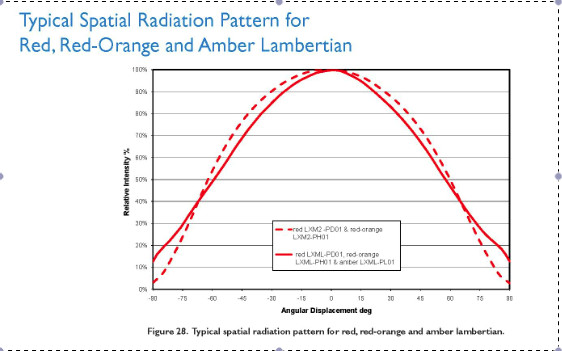
It's a little hard to see but the LEDs retain about 70% of light output at an angle of 45%, quite a bit more than the required 30%. Click on the attachment for a larger view. For comparison, here is a vid of my Range Rover OEM LEDs:
http://youtu.be/aDIP4SMLI-A
In addition, NHTSA requirements DO NOT take readings from one brake light assembly over to the other. So, if you are looking at the left assembly, then the right assembly doesn't even factor into the requirements. You only measure the light output and angles of one unit at a time. In fact, check out sometime OEM LED taillights and you'll see that when lined up straight with one side of the car, the light output of the other assembly is greatly reduced.
Finally, what we all want are taillights that are greater than the stock output so the units can be seen safely by those behind. Not only does this redesign appear to exceed federal standards but the light output is greatly enhanced from the original version. For me that's a winning proposition.
I've now stared at more OEM LED taillights than I ever care to see including my Range Rover and my friend Dean's (former FD owner) Nissan GTR:
As an aside, the GTR is an absolute beast and an awesome performer. Still don't know how a 3,800 lb. car can be that quick (0-60 in 2.9 seconds) and handle that well.
Back to viewing angles. My conclusion is that all LED (and incandescent bulbs for that matter) taillights lose intensity as you go further away from the center or axis of the taillight assembly. This does include what I have done with my modifications.
I can however report that my LED modifications have a higher degree of intensity "off axis" or at a larger viewing angle than any other OEM assembly I have observed including my Range Rover, Dean's GTR, and several other BMWs I have inspected. So the short is, I think we're good to go.
So is it okay to lose intensity as you go from the left to the right of the LED assembly? The answer is yes and NHTSA rules actually allow quite a bit of light loss the further the angle you go from the "center" of the assembly. From one of my previous posts, here are the angles used by NHTSA for testing:
Stop lamp 15� UP-45� IB 15� UP-45� OB 0.3
15� DOWN-45� IB 15� DOWN-45� OB
So, testing would be done on each assembly and light measurements would be taken from a horizontal and vertical "center" of each taillight. NHTSA would measure the intensity from the dead center of each taillight and then take additional measurements going to the left and then to the right by 45% and then by going up and down by 15%. They would then add up the total intensity of all these measurements with a minimum and not to exceed rating and they would then have a minimum rating for the furthest left and right readings. As I understand it (kind of difficult to follow all the regs) the furthest out points need to be around 30% of the center axis points. Could actually be less than this though but I am not sure.
This is why it is okay to lose intensity from left to right and why OEM LED units also lose intensity at angles and I would point out that this LED mod loses less light at the furthest angles than any other OEM unit I have observed. Why is this? Because of the 125% viewing angle LED used and the amount of light they retain at viewing angles of 45% and greater. Here is a graph of the light output intensity of the LEDs used in the brakes:
It's a little hard to see but the LEDs retain about 70% of light output at an angle of 45%, quite a bit more than the required 30%. Click on the attachment for a larger view. For comparison, here is a vid of my Range Rover OEM LEDs:
http://youtu.be/aDIP4SMLI-A
In addition, NHTSA requirements DO NOT take readings from one brake light assembly over to the other. So, if you are looking at the left assembly, then the right assembly doesn't even factor into the requirements. You only measure the light output and angles of one unit at a time. In fact, check out sometime OEM LED taillights and you'll see that when lined up straight with one side of the car, the light output of the other assembly is greatly reduced.
Finally, what we all want are taillights that are greater than the stock output so the units can be seen safely by those behind. Not only does this redesign appear to exceed federal standards but the light output is greatly enhanced from the original version. For me that's a winning proposition.
^ good question. None of the superbrightleds that I have tried are very good. I've got some extra LEDs laying around that I might try. I know I can get them brighter but I've been thinking about using an acrylic bar in the center section so when you apply the brakes you'd see a solid light instead of three individual lights. Check out the BMWs for what I am considering. They have led lighted acrylic bars in the taillights to achieve the look. The put one led in each end of the bar to light the whole bar. Don't like the BMW taillights as it is a bit fussy for me but I think thenacic bar approach might be pretty cool in the center section. I've got an extra one of these to play around with. If it works I'll probably redo the LEDs I have in my 99 spec front turn signals to use the acrylic bar. My thought here is to heat up and bend the bar so it is a curvy swath of light that function as DRLs. Well see.

Feeling a bit better now, at least enough to sneak around and use the dremel when the wife wasn't here 
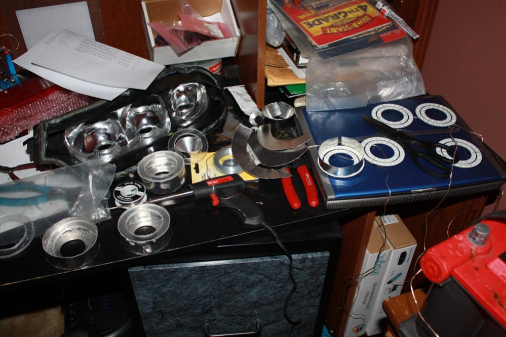
I made a bit of progress. Got the acrylic rings cut. I haven't removed the plastic protectant on them yet, they will get much clearer once I do. I also went ahead and cut the reflectors out. My brake light LED's also showed up in the mail. I think now I just have to spend the time to get it all fitting correctly, glued in place and in the housing.
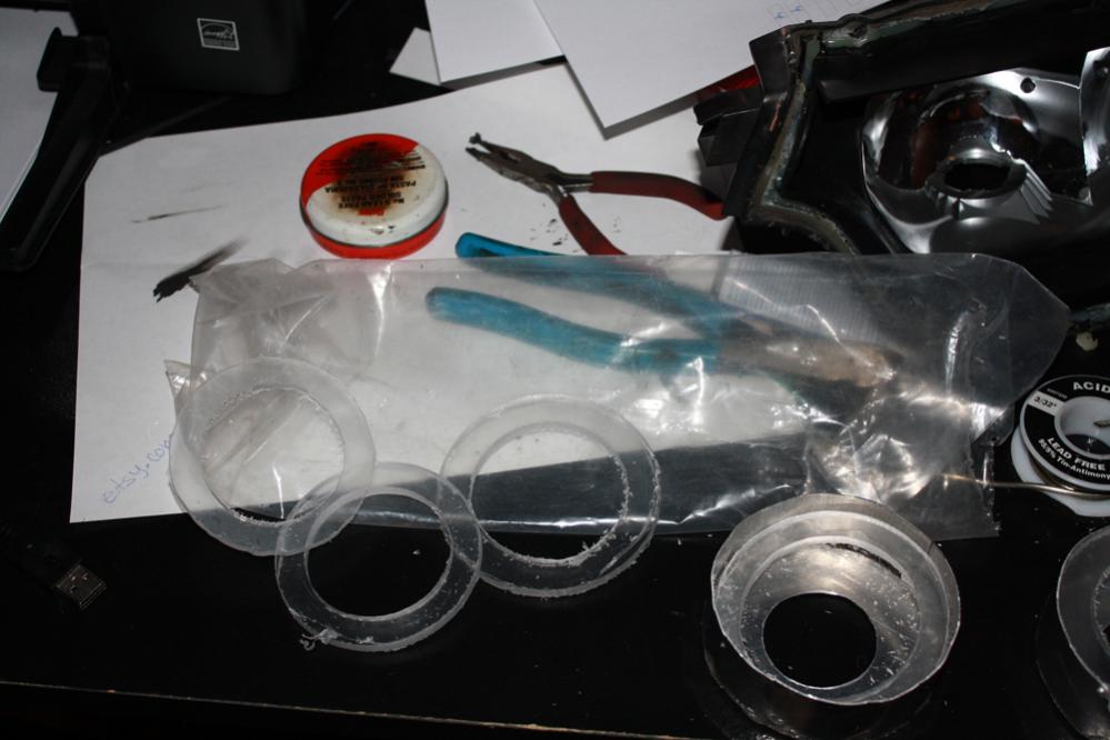
I made a bit of progress. Got the acrylic rings cut. I haven't removed the plastic protectant on them yet, they will get much clearer once I do. I also went ahead and cut the reflectors out. My brake light LED's also showed up in the mail. I think now I just have to spend the time to get it all fitting correctly, glued in place and in the housing.
^ Looking good Bryan. You are certainly on the right track. Question - from the lens pic you've posted, you are not using 99 spec lights? Are you planning on doing that conversion as well?
You'll need to as this mod is meant for Theorie modded lights or 99 spec ones.
Nice work overall and looking forward to more progress.
You'll need to as this mod is meant for Theorie modded lights or 99 spec ones.
Nice work overall and looking forward to more progress.
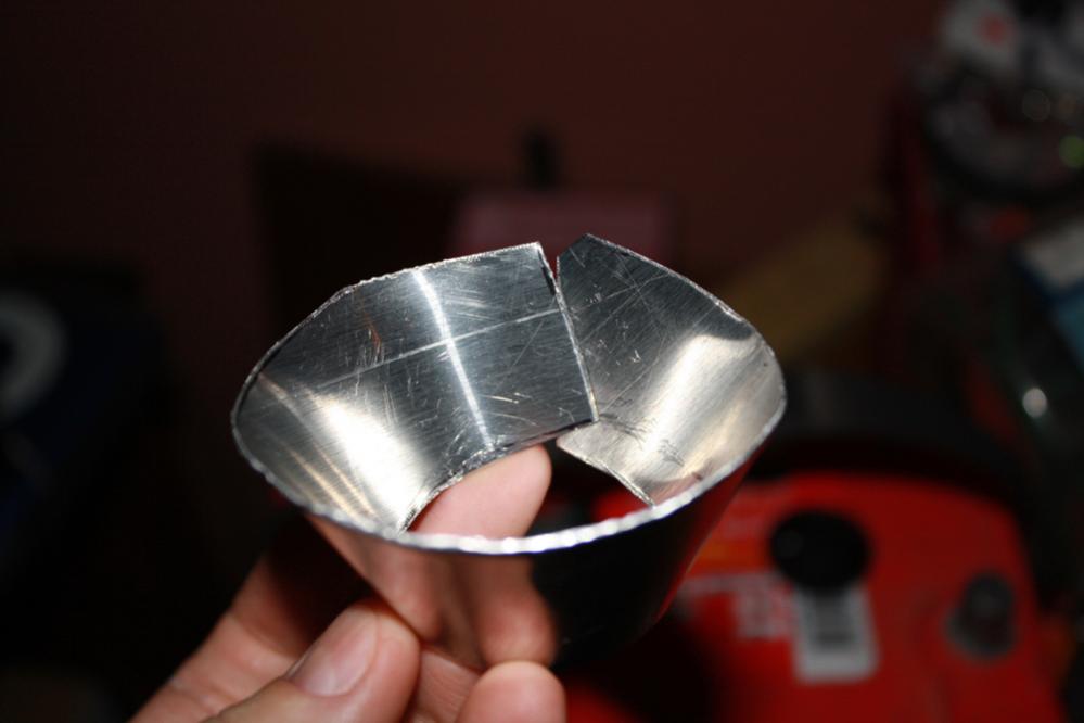
I think people might understand why I used "soda can" aluminum now...
This is what happens when you use aluminum flashing:
You're going to get a ton of light-bleed and the light ring isn't going to be perfect.
Compare that to one of my "soda can" aluminum units from my first prototype:
Anyone else going the DIY route might want to pick up a pack of these, as it will be a lot easier to work with:

^ You can also use an electric palm-held sander to make the painted side silver.
It also looks like you guys are using a pretty shoddy template for tracing/cutting these, if any DIY'ers want the original just let me know. I never said I was unwilling to share it. lol
Cheers!
Flashing is unnecessarily thick doesn't roll properly, it's hard to cut
This is what happens when you use aluminum flashing:
You're going to get a ton of light-bleed and the light ring isn't going to be perfect.
Compare that to one of my "soda can" aluminum units from my first prototype:
Anyone else going the DIY route might want to pick up a pack of these, as it will be a lot easier to work with:
^ You can also use an electric palm-held sander to make the painted side silver.
It also looks like you guys are using a pretty shoddy template for tracing/cutting these, if any DIY'ers want the original just let me know. I never said I was unwilling to share it. lol
Cheers!
Flashing is unnecessarily thick doesn't roll properly, it's hard to cut
^ Looking good Bryan. You are certainly on the right track. Question - from the lens pic you've posted, you are not using 99 spec lights? Are you planning on doing that conversion as well?
You'll need to as this mod is meant for Theorie modded lights or 99 spec ones.
Nice work overall and looking forward to more progress.
You'll need to as this mod is meant for Theorie modded lights or 99 spec ones.
Nice work overall and looking forward to more progress.
I think people might understand why I used "soda can" aluminum now...
This is what happens when you use aluminum flashing:
You're going to get a ton of light-bleed and the light ring isn't going to be perfect.
Compare that to one of my "soda can" aluminum units from my first prototype:
Anyone else going the DIY route might want to pick up a pack of these, as it will be a lot easier to work with:
^ You can also use an electric palm-held sander to make the painted side silver.
It also looks like you guys are using a pretty shoddy template for tracing/cutting these, if any DIY'ers want the original just let me know. I never said I was unwilling to share it. lol
Cheers!
Flashing is unnecessarily thick doesn't roll properly, it's hard to cut
Something like a soda can that was thicker would be ideal Id think.
edit: btw feel free to share your templates if you are willing. After a little thought using the bottom of the soda can for the inside (where literally no structural integrity is needed) and rounded flashing on the outside might be a better combination?
http://www.rotaryaddicts.com/?page_id=446
I wont argue that your picture doesnt look better. That being said, my setup is actually just sitting and a quick mockup for pictures. (i.e. if I turned it upside down the whole thing would fall apart) I plan to ensure its sitting better upon final completion. I've got a tig in the garage and have tig'ed alum this thin before. I'll probably get it "perfect" then go tig it together. I havent really thought about it too much further.
Something like a soda can that was thicker would be ideal Id think.
Something like a soda can that was thicker would be ideal Id think.
The can's diameter is too small to simply be "sliced" so either way you have to make it into a sheet first:
Cut off both ends so you have a cylinder, then cut the cylinder and unroll it into a sheet. This way you can trace the patterns onto it.
I tried a variety of sheet aluminum (flashing from home depot and other thicknesses that I ordered from metal supply shops) and I found the sheets cut from cans worked best overall.
If you want to spend time trying to cut thicker metal and then trying to weld it, be my guest, but just a heads up, the can aluminum works perfect and doesn't need to be welded.

There really is no need for the acrylic circles the stock taillight lens is already diffused so placing the leds further back will create the uniform look. Also just a fun fact while I had a set of oem 99 spec tails I was measuring the circles to get dimensions for my conversion and I found that the turn signal is actually oval instead of a circle.
^The acrylic rings hold the reflectors in the units and they separate the brake light from the parking lights so they are a necessary part of the component. You are correct though that the taillight lens serves as a diffuser and if you move the lights further back then an extra "diffuser" like the original Theorie lights uses is completely unnecessary.
In fact, as I've posted with light meter testing results, the extra Theorie diffuser greatly negatively affects the light output without serving any positive purpose. By simply polishing the diffuser one can increase the parking light output by around 5X as I recall. I had posted up those results but have no idea if they are in this part of the thread or the old "Theorie First Production Run LED Taillight Conversion Review: IMPORTANT INFORMATION (https://www.rx7club.com/shops-part-suppliers-vendors-206/theorie-first-production-run-led-taillight-conversion-review-important-information-976420/) or if the info has been removed completely.
In fact, as I've posted with light meter testing results, the extra Theorie diffuser greatly negatively affects the light output without serving any positive purpose. By simply polishing the diffuser one can increase the parking light output by around 5X as I recall. I had posted up those results but have no idea if they are in this part of the thread or the old "Theorie First Production Run LED Taillight Conversion Review: IMPORTANT INFORMATION (https://www.rx7club.com/shops-part-suppliers-vendors-206/theorie-first-production-run-led-taillight-conversion-review-important-information-976420/) or if the info has been removed completely.
I think people might understand why I used "soda can" aluminum now...
This is what happens when you use aluminum flashing:
You're going to get a ton of light-bleed and the light ring isn't going to be perfect.
Compare that to one of my "soda can" aluminum units from my first prototype:
^ You can also use an electric palm-held sander to make the painted side silver.
It also looks like you guys are using a pretty shoddy template for tracing/cutting these, if any DIY'ers want the original just let me know. I never said I was unwilling to share it. lol
Cheers!
Flashing is unnecessarily thick doesn't roll properly, it's hard to cut
Simply put, IMO the use of "soda cans" for metal components and clear tape to hold the pieces together is not acceptable and it is one of the reasons the original "Theorie First Production Run LED Taillight Conversion Review: IMPORTANT INFORMATION" threads was started.
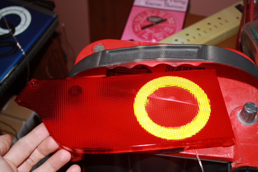
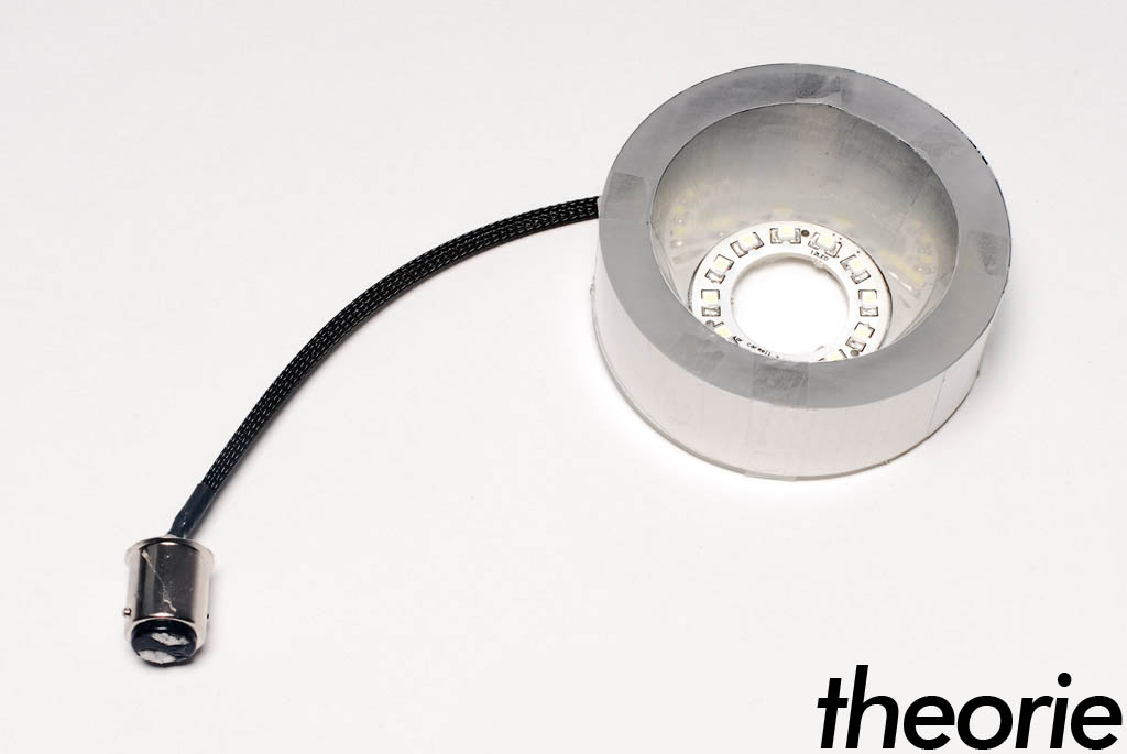
What Bryan has posted is not a finished reflector unit. Here is a pic of what the finished unit will look like:
And the light output:
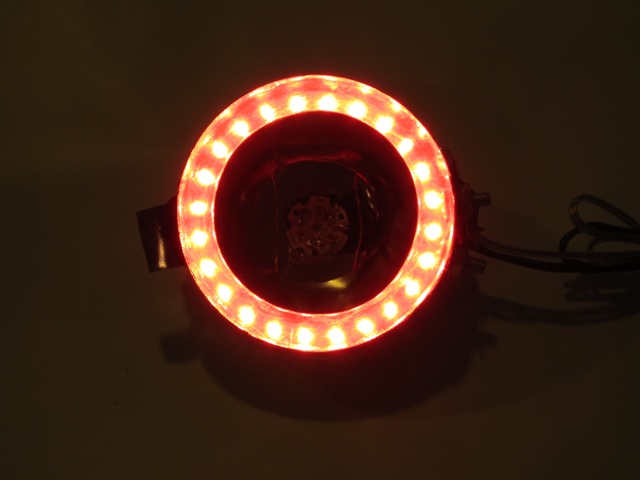
There are no problems with light bleed.
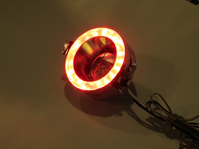
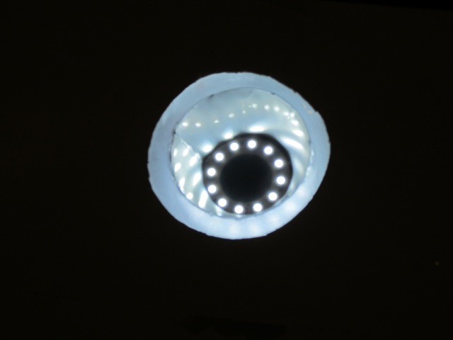
Now here is a pic of one our your units being tested for light output. Look at the inside ring:
Not exactly clean on the inside edge is it? And now one of the light output:
To me it looks like your "soda can" solution actually allows more light bleed than the new design but I'll let the pics speak for themselves.
I tried a variety of sheet aluminum (flashing from home depot and other thicknesses that I ordered from metal supply shops) and I found the sheets cut from cans worked best overall.
If you want to spend time trying to cut thicker metal and then trying to weld it, be my guest, but just a heads up, the can aluminum works perfect and doesn't need to be welded.
If you want to spend time trying to cut thicker metal and then trying to weld it, be my guest, but just a heads up, the can aluminum works perfect and doesn't need to be welded.
Aluminum cans don't work perfectly. Yes, the "soda can" approach has the advantage of being easy to use. It is extremely thin and can be cut with scissors. On the negative side, IMO it's too thin to be used for structural components like the outside metal rings. The vibrations caused by our cars can indeed cause things to break loose and I wouldn't risk the thin metal taped together on an important safety feature like brake lights. In fact, didn't you just experience a vibration problem on your car?
"Once we were off the highway I looked under the car and saw tons of engine oil dripping from everywhere. Long store short, one of my oil line fittings came off. I'm guessing I didn't fully tighten it and it finally vibrated itself loose."

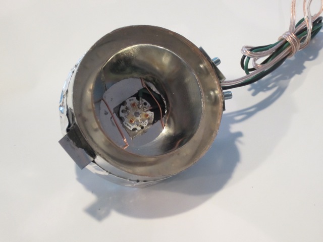
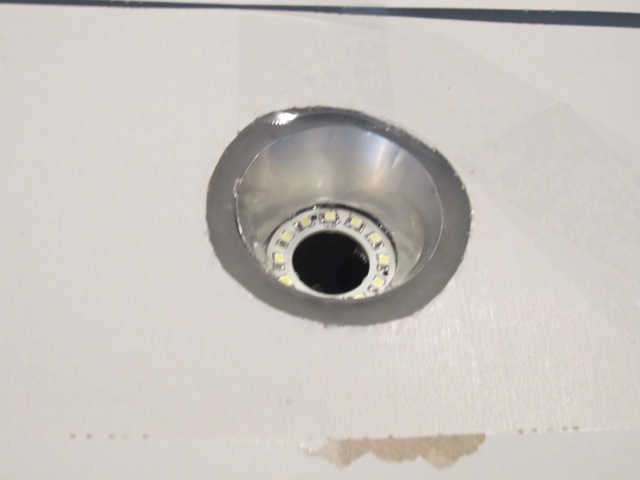
Maybe for the reflectors it could be considered but remember that BOTH SIDES of the reflector metal are used in the assembly, the outer surface to help reflect the brake light and the inside part to reflect the parking lights. So something that is shiny on both sides is needed. Sure you could polish the inside as you point out but this wasn't done on your modifications. Here is a pic of the inside of one of my Theorie units:
Note the inside wasn't polished so the reflector did not reflect properly. Also note the out metal ring was put together backwards so the inside "reflector" was a "black and white" label and for both metal pieces, clear packing tape held the pieces together. IMO this is not acceptable and the proposed new design solutions go a long way to improving the original design. They provide additional structural integrity, they are shiny on both sides as they serve to reflect both outer and inner light and they won't come apart.
The photo I posted above is of a unit before it was installed, not after it was ripped out. It's also one of the prototype units from before production started. And yes, I do use packing tape for part of the process, but its not structural - simply used to keep things in place while adhesives dry. 
David, I do all the work on my car less some fabrication work that involves welding (since I don't have the equipment to do weld).
I posted in the thread to contribute RE: using aluminum can "sheet metal" versus thicker "flashing."
David, I do all the work on my car less some fabrication work that involves welding (since I don't have the equipment to do weld).
I posted in the thread to contribute RE: using aluminum can "sheet metal" versus thicker "flashing."
Last edited by mar3; Dec 1, 2011 at 09:48 PM. Reason: edited for content, removed bannable offenses this time...

PPM? Parts Per Million?
btw David,
On the 75mm rings, do you happen to have any pics of how you attached directly to the 80mm led ring? I was messing with it last night and with my 75mm acrylic rings and metal wrapped around them the metal ring is essentially resting on the led's on the 80mm LED ring. If its working for you I'll just do the same, but I wanted to verify. A pic would be worth a thousand words I'm sure
Private Placement Memorandum
The 80mm turn signal LED rings don't fit into the inside of the metal ring assembly as they do with the brake lights. I placed them over the metal ring so the LEDs fit inside the metal ring but the plastic part of the LED ring covers the back of the metal ring. Sort of like a can top. I then glued the LED ring to the metal outer ring. You then place the back metal cover over the LED ring - I used metal tape to secure the back plate to the assembly. Make sure that you use a silicone sealing over the "live" capacitor sections on the backs of the LED rings or you will short out the rings by placing the metal plate over the LED plastic rings.
I scoured my pics and don't have one of the plastic LED rings placed over the back of the 75 mm rings so maybe you can add up a few pics so others know what to do.
Look forward to seeing your progress.
Last edited by mar3; Dec 3, 2011 at 01:56 PM.
The photo I posted above is of a unit before it was installed, not after it was ripped out. It's also one of the prototype units from before production started. And yes, I do use packing tape for part of the process, but its not structural - simply used to keep things in place while adhesives dry.
David, I do all the work on my car less some fabrication work that involves welding (since I don't have the equipment to do weld).
I posted in the thread to contribute RE: using aluminum can "sheet metal" versus thicker "flashing."
David, I do all the work on my car less some fabrication work that involves welding (since I don't have the equipment to do weld).
I posted in the thread to contribute RE: using aluminum can "sheet metal" versus thicker "flashing."
The point is the metal stock can result in a nice end product that does not have light bleed. It also has the advantages of being more structurally sound which is a positive in cars like ours that experience a lot of vibrational forces. I do agree that some of the metal "flashing" stock is just too thick to use and should not be considered. Home Depot has a lot of stuff that will not work. They do have though the flashing I provided the product link to that works well. Like I stated before, the absolute best stuff (and what I used) was stainless steel stock from Ace Hardare. It is in the specialty sheet metal section and costs about $8-9 per small sheet (6" X 12"). It is not carried at all Aces so I didn't link it but you can look at your local store to see if they have it. It has a mirrored surface which is perfect for this application. This might be a link to it but you'd have to go see in person. Some of the stainless stock is too thick and doesn't have the mirrored surface:
http://www.acehardware.com/product/i...Id=53801957564