
Warning Cluster Teardown - Corrosion and Other Issues (w/ pics)

Joined: Feb 2001
Posts: 29,798
Likes: 128
From: London, Ontario, Canada
You an use the other values as well. The 1-5 should be fine, with the 1 and 2 being most common. I just told you to get the 1N4007 because it's the most generic of them all. The only real difference in the last number is the voltage rating.
Thread Starter
Joined: May 2006
Posts: 4,219
Likes: 3
From: Murfreesboro, TN
Originally Posted by Dr4900n
Looking good on the cleanup.
Incase you were still wondering, VFD stands for Vacuum Flourescent Display. Basically, what was used before LEDs.
http://en.wikipedia.org/wiki/Vacuum_fluorescent_display
Aaron also has a good section on his site about soldering, desoldering, building tips, etc. I'm surprised he didn't link to it, but it looks like you don't really need it.
http://www.aaroncake.net/electronics/index.html
That copper mesh someone mentioned a while ago was probably a desoldering wick (Aaron mentions both types of desoldering tools and when to use them).
I don't know why people kept telling you to junk it (they probably didn't read what you already said). What better hobby is there than rx7s' than rebuilding parts for rx7's?

I'm also not sure why people wouldn't use a de-soldering iron while doing this (as a lot of people don't). It doesn't take very long to do and I found flowing new solder in was easier (I tried to redo some I had put down and ended up just sucking it off and redoing it).
I think people keep telling me to junk it for 2 reasons.
1. They can't or don't bother to read.
2. In general, it tends to be the usual advice given to people in my situation. Most people would junk it if they found a board in the shape mine is. But, this goes back to #1.
I'm kinda surprised Icemark hasn't chimed in on the thread (although Aaron/other's pretty much have it covered). He should tell me how to do the LED's
 . Then again if he did he would give away a trade secret.
Originally Posted by Aaron Cake
You an use the other values as well. The 1-5 should be fine, with the 1 and 2 being most common. I just told you to get the 1N4007 because it's the most generic of them all. The only real difference in the last number is the voltage rating.
The 1-5's were a lot smaller so I figured I couldn't. Once again, Aaron saves the day!
In light of these new developments (in a Walter Cronkite voice), I should have this done Friday and post up the results Monday. I don't look forward to messing with the 24 gauge wiring... but it should be a "fun" challenge. And hopefully I'll have my write-up/how to done sometime next week.
P.S. Thanks for all the help Aaron (and others). I definitely would be screwed without it.
Thread Starter
Joined: May 2006
Posts: 4,219
Likes: 3
From: Murfreesboro, TN
A few updates.
1. I think my solder tip is gone. I can't melt the solder with the tip anymore so that made it kinds difficult to solder what I had left.
2. The 1N4005 is the same size as what the others are. I put that in semi-successfully.
3. Installing the jumper wires was a super duper bitch.
Ok, now for the kicker. I'm 1 step away (besdies putting it together) from being done. There's a part that I have no idea where to solder the wires to. Attached is a picture of it alone and it on the board but de-soldered. I thought I had taken a picture of where it should be... but I guess not.
Thread Starter
Joined: May 2006
Posts: 4,219
Likes: 3
From: Murfreesboro, TN
Where's Icemark when you need him.
Anywho, here's another tip if you try this. Don't rest your finger on a de-soldering iron. They get... kinda... hot.
Anywho, here's another tip if you try this. Don't rest your finger on a de-soldering iron. They get... kinda... hot.
Strength and Honor
Joined: Apr 2006
Posts: 391
Likes: 0
From: CA bay area
I don't know how I missed this thread, I definitely would have chipped in; I'm glad to see you got quick help from others though. That's all I had to say, because I have no idea where the thing in the photo goes! I'd have to take mine apart - maybe AbortRetryFail is dismantling his now and can help out?
Anyway, good job, let's hope it works on the first try!
Anyway, good job, let's hope it works on the first try!
Thread Starter
Joined: May 2006
Posts: 4,219
Likes: 3
From: Murfreesboro, TN
Originally Posted by stevej88na
I don't know how I missed this thread, I definitely would have chipped in; I'm glad to see you got quick help from others though. That's all I had to say, because I have no idea where the thing in the photo goes! I'd have to take mine apart - maybe AbortRetryFail is dismantling his now and can help out?
Anyway, good job, let's hope it works on the first try!
Anyway, good job, let's hope it works on the first try!
If it doesn't work when I plug it in I'm going to throw it across the street.
Really though, I'll probably go check my jumper wires. I had to put in 4 of them. Those damn things are hard to hold while holding solder and an iron. Talk about needing 3 hands...
Thread Starter
Joined: May 2006
Posts: 4,219
Likes: 3
From: Murfreesboro, TN
I got in another warning cluster and opened it up real quick. I found where the wires go.
Now that I know it's pretty obvious.
Hopefully it'll be done this coming week and I'll get the writeup done.
Now that I know it's pretty obvious.
Hopefully it'll be done this coming week and I'll get the writeup done.
Thread Starter
Joined: May 2006
Posts: 4,219
Likes: 3
From: Murfreesboro, TN
shfjklhsadlfklksdjahfklsdalfsdjklah!!!!!!
Good news and bad news.
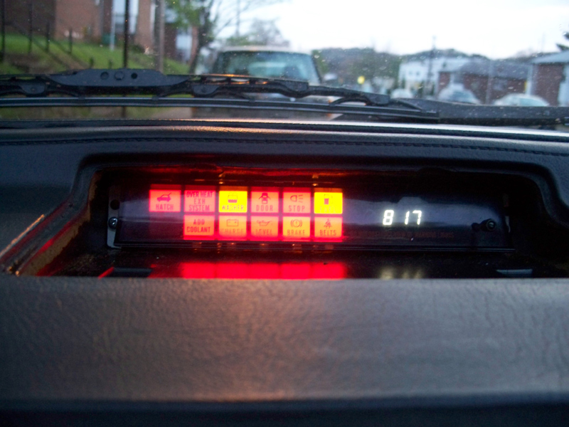
Good: I got it back together and the clock works perfectly.
Bad: The Brake light won't come on.
It just doesn't end...
Oh, and anybody know where to find replacement bulbs? One of mine was burned out. I have a replacement from another cluster (just got it in... yay for being able to compare), but now I need one for that cluster...
Good news and bad news.
Good: I got it back together and the clock works perfectly.
Bad: The Brake light won't come on.
It just doesn't end...
Oh, and anybody know where to find replacement bulbs? One of mine was burned out. I have a replacement from another cluster (just got it in... yay for being able to compare), but now I need one for that cluster...
Last edited by My5ABaby; Feb 28, 2007 at 04:31 PM.
I'm trying to do a project with my warning light cluster and this thread really helped me out. I'm trying to identify this part (https://www.rx7club.com/attachment.p...hmentid=222259). Underneath the tape it is labeled with a triforce-like symbol with the code "T130AR1U1 .C:". Does anyone have an idea what it is and a suitable replacement?
Strength and Honor
Joined: Apr 2006
Posts: 391
Likes: 0
From: CA bay area
My5ABaby had the same question - have you checked out his write-up?
http://howto.globalvicinity.com/gv_w...=263&co=1&vi=1
If the info's not in there you might ask him.
http://howto.globalvicinity.com/gv_w...=263&co=1&vi=1
If the info's not in there you might ask him.

Thread Starter
Joined: May 2006
Posts: 4,219
Likes: 3
From: Murfreesboro, TN
Originally Posted by stevej88na
^ Hmm I should make it ok for this forum to link to GV photos... In the meantime, just check it out in the link.

Thread
Thread Starter
Forum
Replies
Last Post