
Warning Cluster Teardown - Corrosion and Other Issues (w/ pics)

Thread Starter
Joined: May 2006
Posts: 4,219
Likes: 3
From: Murfreesboro, TN
Warning Cluster Teardown - Corrosion and Other Issues (w/ pics)
I removed my idiot light cluster from my car (86) because I wanted to fix my intermittent clock and intermittent brake light issues (the two things I actually use often). Here's some pictures after taking it apart with included questions. 6 questions to be exact.
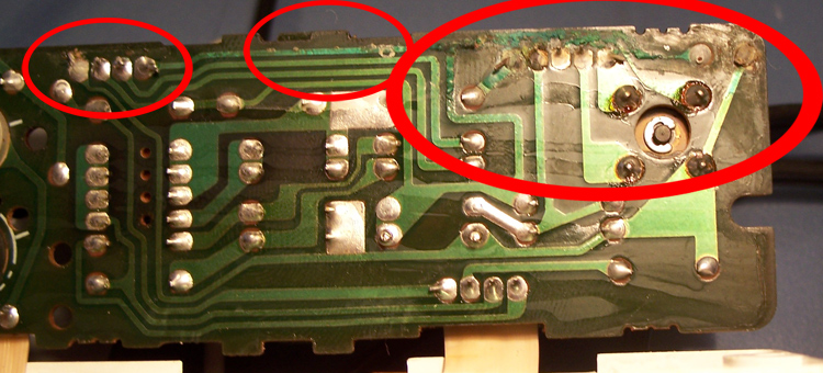
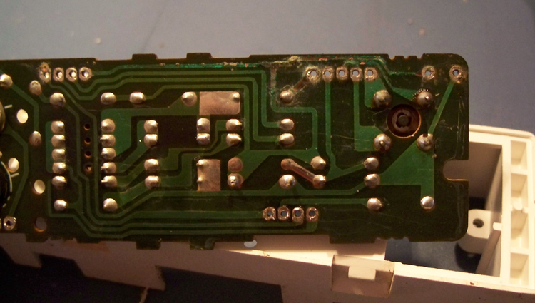
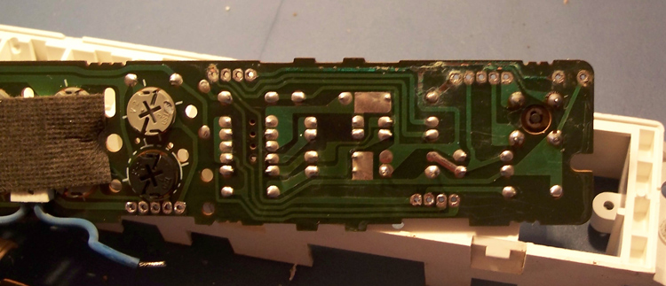
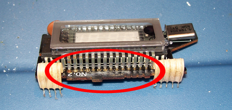
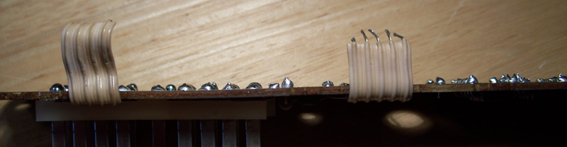
Question 1: Is it possible to fix the corrosion in the following pictures? (Pics 1-3)
Picture 1:
Picture 2:
Picture 3:
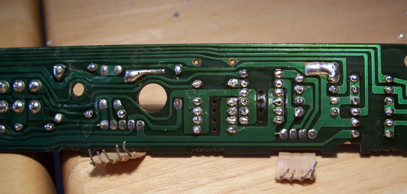
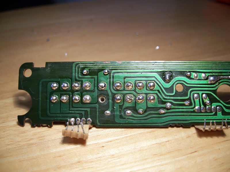
Question 2: Is it possible to fix the breaks in the circuit board connections? (Pics 4 and 5)
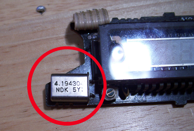
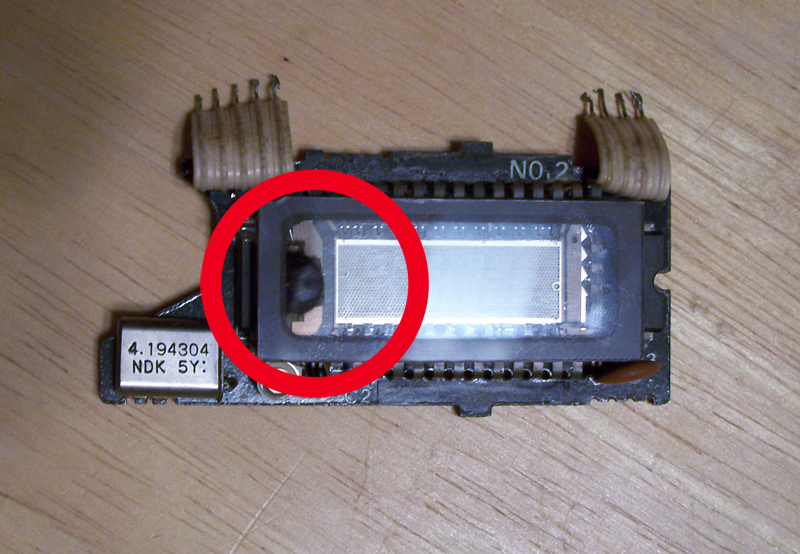
Question 3: Is the corrosion (?) seen on the clock problematic? (Pic 6)
Picture 4:

Picture 5:

Picture 6:

Here's four other random pictures.
Picture 7 is everything that the idiot cluster breaks down into.
Picture 8 is a rusty screw which is one of the ones that held the cluster together. I'm guessing this is a good indication of why I have corrosion.
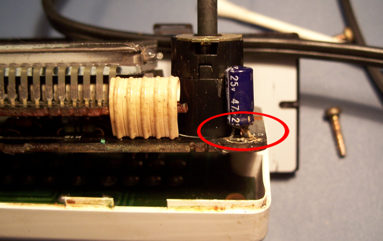
Picture 9 is a rusted resistor that actually fell off shortly after the picture was taken. Question 4: Anyone know where to buy a replacement?
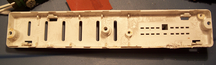
Picture 10 is some weird lines that are on the plastic from the back of the cluster. Question 5: Anyone know what caused them?
Picture 7:

Picture 8: (apparently my camera got a bit happy with the flash)

Picture 9:
Picture 10:

Question 6: Is it worth trying to fix?
Question 1: Is it possible to fix the corrosion in the following pictures? (Pics 1-3)
Picture 1:
Picture 2:
Picture 3:
Question 2: Is it possible to fix the breaks in the circuit board connections? (Pics 4 and 5)
Question 3: Is the corrosion (?) seen on the clock problematic? (Pic 6)
Picture 4:
Picture 5:
Picture 6:
Here's four other random pictures.
Picture 7 is everything that the idiot cluster breaks down into.
Picture 8 is a rusty screw which is one of the ones that held the cluster together. I'm guessing this is a good indication of why I have corrosion.
Picture 9 is a rusted resistor that actually fell off shortly after the picture was taken. Question 4: Anyone know where to buy a replacement?
Picture 10 is some weird lines that are on the plastic from the back of the cluster. Question 5: Anyone know what caused them?
Picture 7:
Picture 8: (apparently my camera got a bit happy with the flash)
Picture 9:
Picture 10:
Question 6: Is it worth trying to fix?
Joined: Feb 2001
Posts: 29,798
Likes: 128
From: London, Ontario, Canada
1. The corrosion doesn't look too bad. Clean it off with a cloth and contact cleaner and you will likely find that there isn't too much damage. I've fixed worse.
2. Install a piece of wire as a jumper.
3. Can't see picture #6.
4. That's a capacitor. You can purchase a replacement at any electronics store.
5. Can't see picture #10.
6. Probably.
2. Install a piece of wire as a jumper.
3. Can't see picture #6.
4. That's a capacitor. You can purchase a replacement at any electronics store.
5. Can't see picture #10.
6. Probably.
Thread Starter
Joined: May 2006
Posts: 4,219
Likes: 3
From: Murfreesboro, TN
Originally Posted by Aaron Cake
1. The corrosion doesn't look too bad. Clean it off with a cloth and contact cleaner and you will likely find that there isn't too much damage. I've fixed worse.
2. Install a piece of wire as a jumper.
3. Can't see picture #6.
4. That's a capacitor. You can purchase a replacement at any electronics store.
5. Can't see picture #10.
6. Probably.
2. Install a piece of wire as a jumper.
3. Can't see picture #6.
4. That's a capacitor. You can purchase a replacement at any electronics store.
5. Can't see picture #10.
6. Probably.
2. Hmmmm, I can try to do that. I hope trying things 80 times doesn't damage the board
 . I'm new to soldering...
3. Fixed (I think).
4. Capacitor, resistor, apples, oranges...
5. Fixed (I think).
6. Good to hear. Sounds like fun.

Originally Posted by 87 t-66
it could probably be repaired and it might work for a little while longer but your best bet is just getting another one for like $10 IMO
1. It's the one that came with the car and I want to keep everything as stock as possible.
2. It's a project for me. I've never soldered anything like this before (or much in general besides playing around with some wiring to practice). I bought a de-soldering iron just yesterday to do this.
3. I'd like a spare to keep around.
a good way to get the solder out is to get a 'solder sucker', just heat up the solder and the tool will suck it right out. what does your tool look like? ive seen others use like a copper mesh to get it out but i havent had good experience that way. replacement resistors and cap's cost like $.10-$.50 each.
Thread Starter
Joined: May 2006
Posts: 4,219
Likes: 3
From: Murfreesboro, TN
Originally Posted by 87 t-66
a good way to get the solder out is to get a 'solder sucker', just heat up the solder and the tool will suck it right out. what does your tool look like? ive seen others use like a copper mesh to get it out but i havent had good experience that way. replacement resistors and cap's cost like $.10-$.50 each.

http://www.radioshack.com/product/in...entPage=search
Originally Posted by Aaron Cake
2. Install a piece of wire as a jumper.
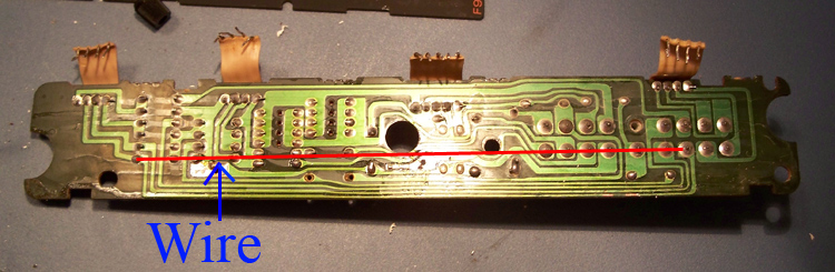
Also, will installing a jumper wire for the corroded areas be a possibility?
Trending Topics
Joined: Feb 2001
Posts: 29,798
Likes: 128
From: London, Ontario, Canada
Yes, that's how you jumper.
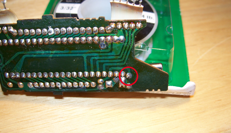
The corrosion around the VFD pins is a bit of a concern, but if the board is still in acceptable condition then you can probably fix it.
The corrosion around the VFD pins is a bit of a concern, but if the board is still in acceptable condition then you can probably fix it.
Thread Starter
Joined: May 2006
Posts: 4,219
Likes: 3
From: Murfreesboro, TN
Originally Posted by Aaron Cake
Yes, that's how you jumper.
The corrosion around the VFD pins is a bit of a concern, but if the board is still in acceptable condition then you can probably fix it.
The corrosion around the VFD pins is a bit of a concern, but if the board is still in acceptable condition then you can probably fix it.
And how can I tell if the board is in acceptable condition?
The parking brake light worked sometimes and when it didn't I could slap the dash a couple times and get it come on. The clock was usually on but never showed anything besides 1:00 (except one time it showed 2:00 and one time it showed 0:00). It did tend to turn off when I turned my headlights on, oddly enough.
Sorry for the, I guess, newb questions, I just know nothing (basically) about electronics but I'm trying to learn.
I guess I could of started with easier projects like fixing my 3800 rpm hesitation and figuring out why my voltage drops about 1.5v when I put my car in reverse... but oh well.


with your corrosion, clean the contacts good and hope for the best. If the circuit card and electrial runs have started to corrode, the card will be done. Once all the corrosion is off, check resistance levels on the runs with a multimeter to see if you have any opens (breaks) or shorts in the lines. Good luck with your project.
Thread Starter
Joined: May 2006
Posts: 4,219
Likes: 3
From: Murfreesboro, TN
Originally Posted by jl1rx7
with your corrosion, clean the contacts good and hope for the best. If the circuit card and electrial runs have started to corrode, the card will be done. Once all the corrosion is off, check resistance levels on the runs with a multimeter to see if you have any opens (breaks) or shorts in the lines. Good luck with your project.

Thread Starter
Joined: May 2006
Posts: 4,219
Likes: 3
From: Murfreesboro, TN
Originally Posted by RETed
I would throw that POS away and get a good used one.
-Ted
-Ted
Originally Posted by My5ABaby
I have another one in now and it works just fine. I'd like to fix this one for several reasons.
1. It's the one that came with the car and I want to keep everything as stock as possible.
2. It's a project for me. I've never soldered anything like this before (or much in general besides playing around with some wiring to practice). I bought a de-soldering iron just yesterday to do this.
3. I'd like a spare to keep around.
if i was you, now thats just saying if i was you, i would redo the whole idiot light cluster and remove the pcb.
Senior Member
Joined: Dec 2002
Posts: 556
Likes: 1
From: singapore
I think you are salvage the cluster still. It might be a bit of work thou . Althou, I got a used S5 cluster ..hehe.. if you wanna update the cluster a bit :P
Last edited by SomeGuy_sg; Jan 26, 2007 at 09:15 AM.
Thread Starter
Joined: May 2006
Posts: 4,219
Likes: 3
From: Murfreesboro, TN
Originally Posted by SomeGuy_sg
I got a used S5 cluster ..hehe.. if you wanna update the cluster a bit :P
Sorry it took so long for me to respond back, but the only way to check and see if you runs are corroded is to check resistance values, if you see almost no resistance you should be good, but if you see huge values thats not good. You just dont check through the circuits, since then the values would be way off. But dur to the age and the pics, the best bet might be to get a new board and go from there.
Thread Starter
Joined: May 2006
Posts: 4,219
Likes: 3
From: Murfreesboro, TN
Originally Posted by jl1rx7
Sorry it took so long for me to respond back, but the only way to check and see if you runs are corroded is to check resistance values, if you see almost no resistance you should be good, but if you see huge values thats not good. You just dont check through the circuits, since then the values would be way off. But dur to the age and the pics, the best bet might be to get a new board and go from there.
Thread Starter
Joined: May 2006
Posts: 4,219
Likes: 3
From: Murfreesboro, TN
I was resoldering and started looking at the clock and found a broken solder joint. As in, I could wiggle it. Could somebody identify what the hell the thing is and what purpose it serves?
Thread Starter
Joined: May 2006
Posts: 4,219
Likes: 3
From: Murfreesboro, TN
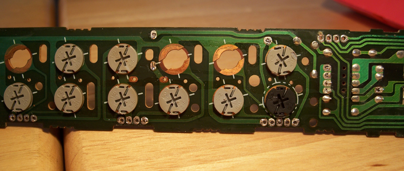
Also, here's some of my progress. Let me know how the soldering/desoldering looks. Keep in mind this is the first time I've soldered a board / used my desoldering iron.
1. How does the contacts around where the lights were look? I'm assuming that's where the lights connect...
2.
3.
4.
5. There's one spot (about 2/3rds of the way over) on this pic that I did go back and fix. It's where 2 of them connected... so... ignore it.
1. How does the contacts around where the lights were look? I'm assuming that's where the lights connect...
2.
3.
4.
5. There's one spot (about 2/3rds of the way over) on this pic that I did go back and fix. It's where 2 of them connected... so... ignore it.
Last edited by My5ABaby; Jan 26, 2007 at 03:39 PM.
Thread Starter
Joined: May 2006
Posts: 4,219
Likes: 3
From: Murfreesboro, TN
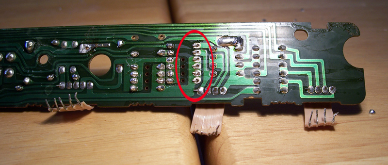
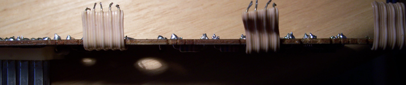
2 more... and a few questions
Do you think I should resolder around the ribbons?
Should I put anything like dielectrical grease on the board when I'm done?
Is the black spot in the 2nd picture normal?
Do you think I should resolder around the ribbons?
Should I put anything like dielectrical grease on the board when I'm done?
Is the black spot in the 2nd picture normal?
Last edited by My5ABaby; Jan 26, 2007 at 03:59 PM.
Thread Starter
Joined: May 2006
Posts: 4,219
Likes: 3
From: Murfreesboro, TN
Well I went to Home Depot and got some 24 gauge wiring so that should be done some time this week. Now I just need a capacitor and I should be good to go.
Unless anyone has comments about my above questions...
Unless anyone has comments about my above questions...