
She Followed Me Home, Honest


Joined: Mar 2001
Posts: 31,859
Likes: 3,243
From: https://www2.mazda.com/en/100th/
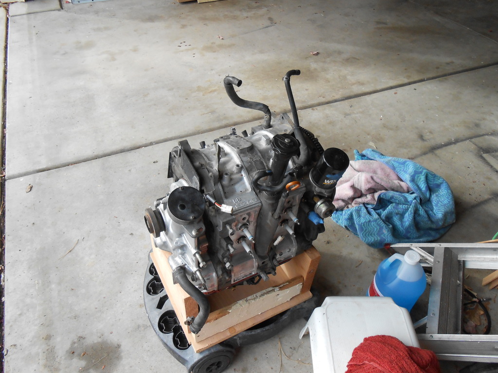
My super high mileage engine precludes me from bitching about how the OMP performs but those flimsy, exposed external lines that meander all over the place just drive me crazy.
Which naturally leads me to considering pre-mixing or at the very least, coming up with a nicer hose alternative. Maybe something like the vacuum spider?
Dunno.
Which naturally leads me to considering pre-mixing or at the very least, coming up with a nicer hose alternative. Maybe something like the vacuum spider?
Dunno.
we just re-(re re re re) built the 25 hour miata, and the fire system uses this aluminum tubing with a plastic cover over it. i think this stuff https://www.pegasusautoracing.com/pr...p?Product=2456
we used it for the fire system, but its so easy to use that i wonder about using it for other stuff.
hmm after looking at the listing, maybe its no good for metering lines, but it would work for vacuum lines, and such
I have a paltry 6k miles on my custom made OMP lines but they are "holding up well". If you decide to go that route it was roughly 40 bucks in material and about an hour of your time. its the OMP line write up in the archives section. I ordered the clamps and hose from mcmaster-carr.
Ben's (Rotary Evolution) braided steel OMP lines have been- and will continue to be, I suspect- fine and if I don't premix, will just get transferred over to the "new" shortblock.
The OMP system is intact and as far as I know, functional.
After following the OMP v. pre-mix debate over the years, I don't think it can be denied that mixing is the better method when viewed strictly from the engine's standpoint, but there are two main downsides.
Obviously, pre-mixing is a bigger PITA for a street car, although I've seen several (seemingly) aborted attempts at an auto injection system that, if successful, would mitigate the hassle.
Also, my S5 ECU requires a MOP signal, so that has to be dealt with.
Keeping the pump plugged in whilst tied up out of the way works I guess, but is just as tacky as the problem it attempts to fix.
This is one of those "problems" I'll spend a lot of time thinking about before just keeping it stock.
Mostly.
Professional Imagineer
Joined: May 2015
Posts: 12
Likes: 0
From: Auburn, Washington, U.S.
After following the OMP v. pre-mix debate over the years, I don't think it can be denied that mixing is the better method when viewed strictly from the engine's standpoint, but there are two main downsides.
Obviously, pre-mixing is a bigger PITA for a street car, although I've seen several (seemingly) aborted attempts at an auto injection system that, if successful, would mitigate the hassle.
Mostly.
Obviously, pre-mixing is a bigger PITA for a street car, although I've seen several (seemingly) aborted attempts at an auto injection system that, if successful, would mitigate the hassle.
Mostly.
Joined: Oct 2003
Posts: 1,600
Likes: 49
From: Norcal/Bay Area, CA
The key point is the ability to move the distribution point from the OMP to somewhere else (preferably under the manifold). Basically, you'd want a fuel rail for feeding the oil injectors.
A little drilling and brazing could connect the oil injector banjo feeds so the hardware itself becomes the manifold. And it installs like a gasket.
Of course I haven't really looked at how everything fits, but if someone had a spare block just sitting around.....
Pros:
-No lines from OMP to injectors, assuming you use an external reservoir to feed one or both ends of the rail.
-Unsure how to feed oil to the injectors. Does it just need to get oil to the injector or does it need more? Tank mounting height can gravity feed or pressurize it via the air pump.
Drawbacks:
-Loses metering functionality of the OMP
-Packaging under the manifold is relatively tight
-Makes the OMP look like a structural member of the engine because there are 6 bolts holding it in place.
Professional Imagineer
Joined: May 2015
Posts: 12
Likes: 0
From: Auburn, Washington, U.S.
Theoretically.
I wish I was driving!
Joined: Dec 2001
Posts: 5,241
Likes: 84
From: BC, Canada
I take it you object to them for aesthetic reasons? If so I can imagine running an electronic OMP which you can relocate, as well as the lines. Since it was only on the front of the engine to read engine speed, you could run some wiring to it to give it your RPM via the ECU, and your tubes would be tucked out of the way.
Theoretically.
Theoretically.
The electronic OMP does not sense the rpm directly from the pump shaft, nor does it use an electronic pump. The electrical connection, as opposed to the mechanical throttle-position linkage on the S4, was introduced to provide better load-based oil metering via a stepper motor, and a Check Engine Light failsafe function for OMP failure.
Relocating the electronic OMP would require plumbing in a oil feed, providing a seperate mechanical drive for the pump section, and putting a block-off plate where the OMP used to reside... And none of which seems aesthetically pleasing, or reliably achieved.
Professional Imagineer
Joined: May 2015
Posts: 12
Likes: 0
From: Auburn, Washington, U.S.
Not quite. The S5 OMP is located on the front cover for the same reasons as the series 4: it provides an oil gallery source of oil to meter, and it provides a gear driven shaft connection to pump the oil through the metering lines.
The electronic OMP does not sense the rpm directly from the pump shaft, nor does it use an electronic pump. The electrical connection, as opposed to the mechanical throttle-position linkage on the S4, was introduced to provide better load-based oil metering via a stepper motor, and a Check Engine Light failsafe function for OMP failure.
Relocating the electronic OMP would require plumbing in a oil feed, providing a seperate mechanical drive for the pump section, and putting a block-off plate where the OMP used to reside... And none of which seems aesthetically pleasing, or reliably achieved.

To reiterate: my objection (at this point) is to the factory implementation of the oil injection, not its use of engine oil or the placement of the "injectors". A presumably critical system seems like it coulda/shoulda been better integrated and less vulnerable.
Ace Racing provided the necessary rubber plugs to seal the remaining openings in the engine (injectors, oil cooler fittings and heater core outlet) and I hope the weather warms up a bit more so I can more comfortably clean the block.
Once clean, we shall see.
Ace Racing provided the necessary rubber plugs to seal the remaining openings in the engine (injectors, oil cooler fittings and heater core outlet) and I hope the weather warms up a bit more so I can more comfortably clean the block.
Once clean, we shall see.

yeah, haven't heard of any failures since i started the lines many years ago and the materials i used were higher quality than i can find out here in the middle of nowhere. lol
i have a new source now for the line but it isn't as fancy as the older stuff i used(what you have).
some have drilled the S5 OMP for a port to run to a reservoir, it's a simple mod that just requires blocking off the oil port to the OMP through the front cover. i have never been a fan of the oil injection system using crankcase oil, but it fills a need.
Last edited by RotaryEvolution; Dec 2, 2015 at 10:23 PM.
Still in cleaning mode, everytime I reposition the block I find all new deposits of grime.
I believe the engine has been apart, the aluminum parts were painted silver-poorly- but the cast iron was left bare and there's more sealant squeeze out than I'd expect from the factory.
As j9 might put it, I spend a lot of time "skiing" when doing mindless tasks and this little diversion happened as I washed the waterpump housing...
On the lower hose boss (inlet) is an untapped/undrilled casting that I think is the turbo water return in boosted cars, left unfinished in the lowly NA.
It appears beefy enough to fit a 5/8" hose barb (probably not a screw in, but a press fit tube should work)...which, coincidentally enough, is the size of the heater core return bung on the radiator.
Last summer, faced with replacing my leaky Godspeed radiator, I was frustrated by the restrictions the stock setup imposes. Were it not for the extra heater fitting, many more generic rads might be considered. Having deleted the stock airbox and mechanical fan, I no longer need the downward angled top hose bung either, a standard straight fitting would do fine. In fact, that would allow for a more generic upper hose as well.
I've already replaced the rad and have no immediate need to do this but can anyone see a problem with bringing the heater return in at the engine side instead of further down the hose at the radiator?
While I have the pump housing in hand there are three other projects planned for it...the heater fitting being theoretical for now.
-I'd like to replace the 90� hose fitting on the back with a straight one. I think the diversion of this hose over the BAC is absurd and a different fitting gives me a cleaner shot to the thermowax.
-Drill/tap the unused boss on the upper (thermostat) neck to accept the BMW fan trigger switch I used on the Z. This switch is 16mm compared to the 22mm Audi part I now use, which requires an adaptor in the upper hose. Be able to clean up the wiring some as well.
-While rooting around I found a metal thermostat cover/hose bung that I must have snagged years ago. No idea what it's off but it looks pretty good...certainly worthy of an attempt at fitting.
Now back to cleaning.
Joined: Mar 2001
Posts: 31,859
Likes: 3,243
From: https://www2.mazda.com/en/100th/
nope none at all, in fact this is how the FD is. pic is FD water pump in FC, one of the reasons the swap is hard, nothing fits! i ended up cutting the FD housing, and putting a piece of pipe on it, and it now lines up exactly with the FC hose, and since i'm using an FC radiator, i kept the FC heater hose.
its an REW block in an FC chassis, no real benefit i know of from the FD pump or housing aside from and likely more cavitation issues with the crap quality bent SS impeller. well that and you save about 3lbs from the stock FC heavy cast iron water pump.
Joined: Mar 2001
Posts: 31,859
Likes: 3,243
From: https://www2.mazda.com/en/100th/
mine is an REW in an FC chassis which i only did, because thats what i came up with when i swept the floor. i would have been way way way ahead to just sell the FD engine, buy a JDM T2 engine, and rebuild that, and just have a stock car
all those threads about REW swaps couldn't all have been wrong. 
i look at an REW and then an FC and just say "nope, not gonna do it", and i have about 3 complete blocks to spare. one of the main benefits of the REW being the larger intake ports, i still don't believe i have seen anyone put up bigger numbers on a 35R than i have with an FC block(that includes REW owners) regardless of that difference, and we're still shooting for more from it.
i look at an REW and then an FC and just say "nope, not gonna do it", and i have about 3 complete blocks to spare. one of the main benefits of the REW being the larger intake ports, i still don't believe i have seen anyone put up bigger numbers on a 35R than i have with an FC block(that includes REW owners) regardless of that difference, and we're still shooting for more from it.
Last edited by RotaryEvolution; Dec 4, 2015 at 04:21 PM.
Cleaning of the "new" shortblock continues and it's harder than it looks...
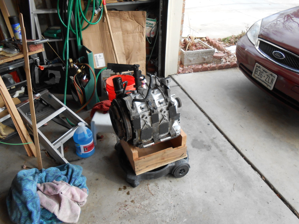
Because I don't plan on disassembling the engine, I've been very concerned/careful about crap getting into the block. I stuffed all the big holes with closed cell foam and then GOOPed ABS covers over them. Smaller holes were plugged with rubber stoppers.
I've had to be careful with water pressure and choice of solvents, trying to maintain sealing but still wanting to get it clean.
One final round and I'll remove the covers and foam, block sand the gasket mating surfaces and then reseal with tape. I think it'll be good enough to paint after that.
Fortunately, only the front and driver side are really exposed with the engine in situ and those are the areas I'll concentrate on.
After cleaning all the gunk off the lower half of the keg, I rediscovered the blanking plug on the front iron and it looks like it may be the same size as the fan trigger, which would be handy.
For those not familiar...there is an Allen keyed plug at the driver side bottom of the front iron. This is a coolant passage (cold weather cars could put a block heater here) and a few years ago I ran two VDO water temp sensors- one in the stock location and one in this blanked spot. They read exactly the same, so it'd be an excellent spot for the efan trigger...if it's a 16mm hole, I'm golden. If not, it can go on the back of the waterpump housing.
After paint (assuming that happens), the engine can rest/cure and my attention will turn to the vac spider and engine wiring harness, both of which I'd like to clean up. I need most of the spider but have made some changes to the intake that could be better integrated (primarily the BAC feed and OMP air bleeds- assuming for now that the OMP is going to remain).
I'd like to reroute the wiring to come across the firewall and enter the engine from the rear (snarky jokes appreciated) instead of going to the strut tower and jumping over to the front of the keg. Not sure how practical this might be but it's easy enough to find out when the motor is all exposed like this.
I have 10 days before I move back over to housesit at Sigfrid's and I want the paint done by then.
Joined: Mar 2001
Posts: 31,859
Likes: 3,243
From: https://www2.mazda.com/en/100th/
C
I'd like to reroute the wiring to come across the firewall and enter the engine from the rear (snarky jokes appreciated) instead of going to the strut tower and jumping over to the front of the keg. Not sure how practical this might be but it's easy enough to find out when the motor is all exposed like this.
I have 10 days before I move back over to housesit at Sigfrid's and I want the paint done by then.
the JDM harness sits on the engine exactly like the US harness, which is good. it also is nearly the same length as the US harness (actually a tad longer). the main difference is that since the JDM ecu is on the other side of the car, whilst the US harness has one lonley wire to do the coolant temp sensor, and the main routing goes with the AFM branch over the river and through the woods (and up a mountain, and circumnavigates the globe). the big bulk of the JDM harness comes out where the coolant temp wire is, and the branch that then goes and does the AFM, is only the AFM, Map sensor and test connector.
i put the thing so it comes out behind the oil filter, instead of in front, and then it goes along the firewall, and into the car. the firewall boot had to move, and then i had to add the wiper wires, as they are on a different harness in japan. you also need to repin the connector under the dash, same piece of plastic, but since the wipers aren't there the pinout is slightly different between US and Japan. the JDM harness is basically the US a/t harness with the wire for the boost gauge, and every JDM car got the same thing, whereas in the US we have 3 variations, m/t, a/t, and turbo.
more food for thought than practical advise, as the JDM harness, being a turbo, has a boost controller and knock sensor where you have VDI and 6pi.
Food- of any kind- is always appreciated.
My current harness (completely stock, albeit rerouted a bit) is just so bulky- a blemish I could overlook if it made things easier, but it doesn't. The intake manifolds still need to come off to get to everything.
The specific trigger for this line of thought was the O2 sensor wire.
If the harness ran the firewall, I could sprout the sensor lead out right next to the sensor itself, probably shave 4-5ft off the wire. Many others are the same.
I'm currently leaning towards premixing. The basic Rtek chip is essentially the same price as the Atkins adaptor setup and the chip allows for all the oil/air hoses to go away, along with the pump itself and its wiring. If I had a S4 this would be a no brainer, the electronic S5 unit makes it a much tougher call, what with the $120 buy in.
It comes down to deciding if the constant hassle (minor as it may be) of premixing is worth eliminating a potential failure point.
Vaingloriously, I kinda think that if manual premixing is too onerous, I could come up with a more automated system...despite the many who have previously failed.
Then again, such a system would actually be moving the complexity from one end of the car to the other (presuming that the theoretical oil tank and pump would be near the fuel tank) and a fault in the system would be just as catastrophic as an OMP failure.
Sheesh.
Joined: Mar 2001
Posts: 31,859
Likes: 3,243
From: https://www2.mazda.com/en/100th/
B, premixing doesn't eliminate a failure point, as you still need to do something.
C, how often do you need to take the intakes off? if you've done everything correctly, its only when changing engines, which should be 10years+