
NA eFan Install


Rotary Freak
Joined: Dec 2006
Posts: 1,791
Likes: 0
From: New Hampshire
It still kicks the fan at EXACTLY the same indicated temp so, RotaMan, I am now absolutely certain that the spot I chose at the beginning of this thread is perfectly suitable and in no way "on the cold side" of the system.
Same sensor right?
Yes, same sensor and the temp gauge was untouched as well.
Looking at the flow chart in the FSM I saw the rad output going across the top of the engine, reversing direction at the rear plate and then returning at the bottom, so basically, up and down not side to side.
Although I'd be interested to have this cleared up just for knowledge's sake, practically speaking- and at least to my satisfaction- I think the original site was fine.
In fact, from an installation standpoint it's far superior to the upper hose location since there is no fabrication involved and the wiring is shorter/ more easily hidden.
Plus, the fan would still trigger on in the unlikely event of a thermostat failure.
On the other hand, I can't help but wonder why Mazda didn't use that spot, indeed, why even drill/tap that location just to plug it up and never mention it?
Rotary Freak
Joined: Dec 2006
Posts: 1,791
Likes: 0
From: New Hampshire
I will look at my spare parts, use some water or air to determin the path and I will let you know. I was going to put a temp sensor on the side of the engine as well and looked at the FSM and it looked like it was in the path of the cooled coolant.
OK, slight update.
No way to make this look good, so...my adapted thermo housing leaked.
Just a little mind you, but it leaked.
After running the car I could hear hissing and smell hot coolant but could not pinpoint where it was coming from till I removed the alternator and was able to steal a glimpse of the back of the housing.
That's where it was although I was not able to determine exactly where the leak originated- between the housing and the adaptor or the adaptor and the new cover...anyway, didn't matter, it had to be fixed.
So off it all came and I spent some quality time reexamining the whole setup.
I was sorely tempted to just reinstall the stock unit and call it a day but that would have required procuring a new stock upper hose and I knew that was going to be difficult on short notice (I had to order in the hose last time I replaced it) so I was motivated to make this new setup work- if only for the short term.
Idly playing with the stock and new housing I noticed that one of the new housing's mounting holes (it has two compared to the stocker's three) was an exact match to the original's and all I lacked was a properly positioned opposite hole and I could dispense with the adaptor plate altogether.
Some test positioning showed that there was enough meat on the waterpump housing flange to accommodate another hole if I was careful not to drill too deeply.
I was successful.
*no pics of this process...if you're capable of drilling/tapping you don't need 'em...*
I installed studs into the two holes (the NA's use three 6mm retaining bolts and my replacement housing originally used two 8mm bolts, so I had some wiggle room to get it aligned correctly over the sealing o-ring) and ended up with this...

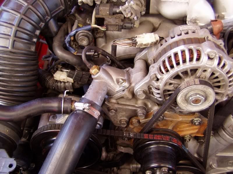
All in all, a much more satisfactory solution (admittedly a solution to a problem of my own making, but...) which eliminates an extra sealing surface and the mickey mouse adaptor plate.
Car has survived three heat/cool cycles with nary a drop of leakage.
Basically, this is an almost completely useless mod but I thought I'd finish it's description properly anyway just in case anyone else is silly enough to try it.
Given what I've learned, I could replicate this in under an hour.
Like that matters.
And, before anyone asks...there is @ 1" clearance between the airpump belt and the bottom of the hose, so there is no danger of the hose getting abraded whilst the engine is running.
Were that belt to break, well, all bets are off.
No way to make this look good, so...my adapted thermo housing leaked.
Just a little mind you, but it leaked.
After running the car I could hear hissing and smell hot coolant but could not pinpoint where it was coming from till I removed the alternator and was able to steal a glimpse of the back of the housing.
That's where it was although I was not able to determine exactly where the leak originated- between the housing and the adaptor or the adaptor and the new cover...anyway, didn't matter, it had to be fixed.
So off it all came and I spent some quality time reexamining the whole setup.
I was sorely tempted to just reinstall the stock unit and call it a day but that would have required procuring a new stock upper hose and I knew that was going to be difficult on short notice (I had to order in the hose last time I replaced it) so I was motivated to make this new setup work- if only for the short term.
Idly playing with the stock and new housing I noticed that one of the new housing's mounting holes (it has two compared to the stocker's three) was an exact match to the original's and all I lacked was a properly positioned opposite hole and I could dispense with the adaptor plate altogether.
Some test positioning showed that there was enough meat on the waterpump housing flange to accommodate another hole if I was careful not to drill too deeply.
I was successful.
*no pics of this process...if you're capable of drilling/tapping you don't need 'em...*
I installed studs into the two holes (the NA's use three 6mm retaining bolts and my replacement housing originally used two 8mm bolts, so I had some wiggle room to get it aligned correctly over the sealing o-ring) and ended up with this...
All in all, a much more satisfactory solution (admittedly a solution to a problem of my own making, but...) which eliminates an extra sealing surface and the mickey mouse adaptor plate.
Car has survived three heat/cool cycles with nary a drop of leakage.
Basically, this is an almost completely useless mod but I thought I'd finish it's description properly anyway just in case anyone else is silly enough to try it.
Given what I've learned, I could replicate this in under an hour.
Like that matters.
And, before anyone asks...there is @ 1" clearance between the airpump belt and the bottom of the hose, so there is no danger of the hose getting abraded whilst the engine is running.
Were that belt to break, well, all bets are off.
Rotary Freak
Joined: Dec 2006
Posts: 1,791
Likes: 0
From: New Hampshire
Looks good. If that doesn't work, if all your looking for is a spot for the sensor, on the back of the S5 water pump housing, atleast the spare I have there is a machined spot where it looks as though mazda could drill and tap a spot for a sensor. Real smooth spot. I put my GReddy temp gauge sensor on the back of mine but I had to smooth the area out first. Maybe you could do this? More work though..
Also earlier stated, the adaptors on summit racing.
Or if that spot on the side of the engine does infact return the thermostat, maybe go there.
Also earlier stated, the adaptors on summit racing.
Or if that spot on the side of the engine does infact return the thermostat, maybe go there.
I'm still convinced that my original location would be fine, and that eliminates the necessity for any of this.
I'm justifying the extra work by noting that I did remove the plastic stock piece in favor of a sturdier metal housing which - in theory at least- could be considered an upgrade.
That's my story and I'm stickin to it.
I'm justifying the extra work by noting that I did remove the plastic stock piece in favor of a sturdier metal housing which - in theory at least- could be considered an upgrade.
That's my story and I'm stickin to it.

im going to check for that sensor (off my TII) and see if my TII block has that passage you first had the sensor in. i need to run a sensor for a aftermarket guage and for an E-fan. i can use the S4 elbow above the thermostat for the guage and the other passage for the E-fan

Joined: Dec 2003
Posts: 6,598
Likes: 10
From: Temple, Texas (Central)
I found 3 of them, and those cars have been there for years. I doubt they will be gone. If they are, oh well. There are 2 other junkyards with truly massive selections (one is larger than the adjacent town) near my house that I'm sure will have them. Being out in mid 90's weather for several hours isn't my idea of fun.
Joined: Feb 2001
Posts: 29,798
Likes: 128
From: London, Ontario, Canada
Wait a sec...people keep referring to the upper rad hose as the "cool" side. That's not true at all. The water pump sucks from the bottom hose, circulates through the engine, and then back into the rad via the upper hose. So it's only "cool" until the thermostat opens up.
Update time.
Fan has been working fine and I decided to finalize the install by redoing the wiring.
Aaron had pointed out that my switch placement was less than optimal (and I agreed) so I rethought the entire system.
I decided that removing all the electrical components (the HIGH/LOW speed switch and the relay) from the engine bay was the best way to go.
I procured an ON-OFF-ON rocker switch that was suitable for the unused blank spot on the console next to the security system light.
Then I bought a 25" three conductor extension cord to use for the cabling.
This was perfect as it had three 10ga copper stranded wires all nicely bundled in a protective sheath and was dirt cheap at $2.95 at the surplus store.
A second 30 amp relay completed the supplies.
Previously I was using a heavy duty toggle switch to switch the power from HIGH to LOW fan speed but I didn't want all that current running in my console so now the switch just sends ignition controlled +12v power to two relays which handle the heavy current.
The main power comes from the battery (located in the passenger side bin).
The relays are located under the glove box in the area previously occupied by the auto seat belt computer.
Here is a schematic of the new wiring...
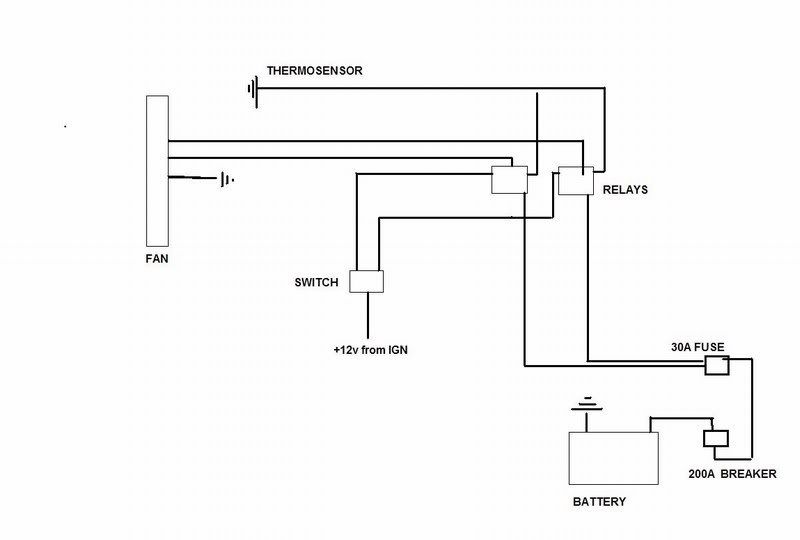
While I was at it I relocated the thermoswitch back to it's original location in the bottom of the front iron.
From the 30a fuse (located in the battery bin) I ran the cable with all three legs tied together to feed the relays.
From the relays to engine compartment one wire feeds the fan's HIGH speed, one feeds the LOW speed and the third carries the relay's ground signal to the thermoswitch.
This made for a pretty easy and neat install.
So now I have a fairly robust and weather tight fan system with the ability to vary fan speed on the fly from within the cabin.
This may be overkill as I have yet to need the HIGH fan speed but the weather has cooled lately so we'll see what next summer is like.
If Al Gore is right I may be on HIGH all the time...
Fan has been working fine and I decided to finalize the install by redoing the wiring.
Aaron had pointed out that my switch placement was less than optimal (and I agreed) so I rethought the entire system.
I decided that removing all the electrical components (the HIGH/LOW speed switch and the relay) from the engine bay was the best way to go.
I procured an ON-OFF-ON rocker switch that was suitable for the unused blank spot on the console next to the security system light.
Then I bought a 25" three conductor extension cord to use for the cabling.
This was perfect as it had three 10ga copper stranded wires all nicely bundled in a protective sheath and was dirt cheap at $2.95 at the surplus store.
A second 30 amp relay completed the supplies.
Previously I was using a heavy duty toggle switch to switch the power from HIGH to LOW fan speed but I didn't want all that current running in my console so now the switch just sends ignition controlled +12v power to two relays which handle the heavy current.
The main power comes from the battery (located in the passenger side bin).
The relays are located under the glove box in the area previously occupied by the auto seat belt computer.
Here is a schematic of the new wiring...
While I was at it I relocated the thermoswitch back to it's original location in the bottom of the front iron.
From the 30a fuse (located in the battery bin) I ran the cable with all three legs tied together to feed the relays.
From the relays to engine compartment one wire feeds the fan's HIGH speed, one feeds the LOW speed and the third carries the relay's ground signal to the thermoswitch.
This made for a pretty easy and neat install.
So now I have a fairly robust and weather tight fan system with the ability to vary fan speed on the fly from within the cabin.
This may be overkill as I have yet to need the HIGH fan speed but the weather has cooled lately so we'll see what next summer is like.
If Al Gore is right I may be on HIGH all the time...
Winter sucks
Joined: Jan 2004
Posts: 3,083
Likes: 0
From: Newberg, Oregon
On the automatic S5 water pump housing, that smooth area is drilled/tapped for an OEM thermo switch since the automatic S5 had a stock E-fan for the AC. It would seem to be cheaper to source an automatic water pump housing, and if not cheaper, WAY less work.
 Heck, go get a drill/tap and do it yourself. Mazda probably put it there for a reason. I can take pictures of the auto housing if you wish... I also have the stock sensor... but I'll be installing it for a possible use in the future.
Joined: Apr 2005
Posts: 3,785
Likes: 30
From: And the horse he rode in on...
Back from the *dead*-Update?
So off it all came and I spent some quality time reexamining the whole setup.
I was sorely tempted to just reinstall the stock unit and call it a day but that would have required procuring a new stock upper hose and I knew that was going to be difficult on short notice (I had to order in the hose last time I replaced it) so I was motivated to make this new setup work- if only for the short term.
Idly playing with the stock and new housing I noticed that one of the new housing's mounting holes (it has two compared to the stocker's three) was an exact match to the original's and all I lacked was a properly positioned opposite hole and I could dispense with the adaptor plate altogether.
Some test positioning showed that there was enough meat on the waterpump housing flange to accommodate another hole if I was careful not to drill too deeply.
I was successful.
*no pics of this process...if you're capable of drilling/tapping you don't need 'em...*
I installed studs into the two holes (the NA's use three 6mm retaining bolts and my replacement housing originally used two 8mm bolts, so I had some wiggle room to get it aligned correctly over the sealing o-ring) and ended up with this...
All in all, a much more satisfactory solution (admittedly a solution to a problem of my own making, but...) which eliminates an extra sealing surface and the mickey mouse adaptor plate.
Car has survived three heat/cool cycles with nary a drop of leakage.
Basically, this is an almost completely useless mod but I thought I'd finish it's description properly anyway just in case anyone else is silly enough to try it.
Given what I've learned, I could replicate this in under an hour.
thx.
It "remained successful"- to the extent that it didn't leak or seem to have any effect on the coolant flow- for about two months.
I'm now back to stock but for the life of me can't remember what precipitated the change.
Probably something trivial like boredom or aesthetics.
I'm now back to stock but for the life of me can't remember what precipitated the change.
Probably something trivial like boredom or aesthetics.
For what it's worth, I just adapted my S4 TII thermostat cover/filler neck to accept an aftermarket 3/8" -18 thermoswitch. All it took was removing the cover & expanding the existing threads for the stock thermoswitch with a larger tap. It seems almost all aftermarket thermoswitches are 3/8" -18 pipe thread, and the stock hole's thread pitch happens to be the same.
All turbos and automatics came with this switch in the cover, but it's a 215F switch for the tiny backup e-fan. The location can be drilled a tapped on a manual NA that has no stock e-fan. In my case, I installed a 195F/185F switch in place of the stock switch. Attached is a picture of the stock switch. No pictures of the new one yet. It got dark on me, while I was finishing up the install today.
All turbos and automatics came with this switch in the cover, but it's a 215F switch for the tiny backup e-fan. The location can be drilled a tapped on a manual NA that has no stock e-fan. In my case, I installed a 195F/185F switch in place of the stock switch. Attached is a picture of the stock switch. No pictures of the new one yet. It got dark on me, while I was finishing up the install today.
Joined: Apr 2005
Posts: 3,785
Likes: 30
From: And the horse he rode in on...
It "remained successful"- to the extent that it didn't leak or seem to have any effect on the coolant flow- for about two months.
I'm now back to stock but for the life of me can't remember what precipitated the change.
Probably something trivial like boredom or aesthetics.
I'm now back to stock but for the life of me can't remember what precipitated the change.
Probably something trivial like boredom or aesthetics.
Ya wanna sell me that neck for say, $10 shipped?
For what it's worth, I just adapted my S4 TII thermostat cover/filler neck to accept an aftermarket 3/8" -18 thermoswitch. All it took was removing the cover & expanding the existing threads for the stock thermoswitch with a larger tap. It seems almost all aftermarket thermoswitches are 3/8" -18 pipe thread, and the stock hole's thread pitch happens to be the same.
All turbos and automatics came with this switch in the cover, but it's a 215F switch for the tiny backup e-fan. The location can be drilled a tapped on a manual NA that has no stock e-fan. In my case, I installed a 195F/185F switch in place of the stock switch. Attached is a picture of the stock switch. No pictures of the new one yet. It got dark on me, while I was finishing up the install today.
All turbos and automatics came with this switch in the cover, but it's a 215F switch for the tiny backup e-fan. The location can be drilled a tapped on a manual NA that has no stock e-fan. In my case, I installed a 195F/185F switch in place of the stock switch. Attached is a picture of the stock switch. No pictures of the new one yet. It got dark on me, while I was finishing up the install today.

For my fan thermoswitch I used Alumiweld to braze in a 3/8" aluminum bung on the hot side of the radiator, then installed a 200/185* 3/8" switch. Switch and bungs came from Summit Racing. I also brazed in a bung for a fitting on the lower cold side for the heater loop return. Very nice product, I am pleased with the ease of use and the results. Bungs have been in place for a couple of weeks.

Thread
Thread Starter
Forum
Replies
Last Post
24seven_dada
3rd Generation Specific (1993-2002)
20
Nov 10, 2018 12:03 PM
Jeff20B
1st Generation Specific (1979-1985)
73
Sep 16, 2018 07:16 PM