When you click on links to various merchants on this site and make a purchase, this can result in this site earning a commission. Affiliate programs and affiliations include, but are not limited to, the eBay Partner Network.
not that I know of. I made these because I wanted to improve it. Unfortunately there is no adjustment on my kit. Making diferent sized spacers you could stack everything differently but it would take a lot of time and money.
I just wanted to improve and restore the lost roll center. Especially since macpherson strut suspensions want a lot of camber. So these also help me minimize camber loss. I also wanted to improve the roll axis
I totally understand the reason to fix the roll center. I'm just wondering how people are settling on the sizes and parts used. How do you know where to move the mounting points to improve the geometry?
I totally understand the reason to fix the roll center. I'm just wondering how people are settling on the sizes and parts used. How do you know where to move the mounting points to improve the geometry?
I asked a friend what size he used. After it was made I checked my car on the 4 post lit and went with the general rule of having the arms parallel with the floor
I asked a friend what size he used. After it was made I checked my car on the 4 post lit and went with the general rule of having the arms parallel with the floor
Gotcha. I have the software that we use to measure roll centers for circle track cars. I never took the time to measure my FC though. It's a time consuming process to measure the X,Y, and Z for all the joints in the suspension. However, If you ever want to take the time to measure everything on your car I'd gladly enter the numbers into the software and share my results.
when I first set my car up with roll center adjusters I set the tie rods to be parallel with the control arms... I later measured with a bump steer gauge and it was pretty far off. ended up going up about a 1/4" on the tie rod at least. so definitely measure your bump steer
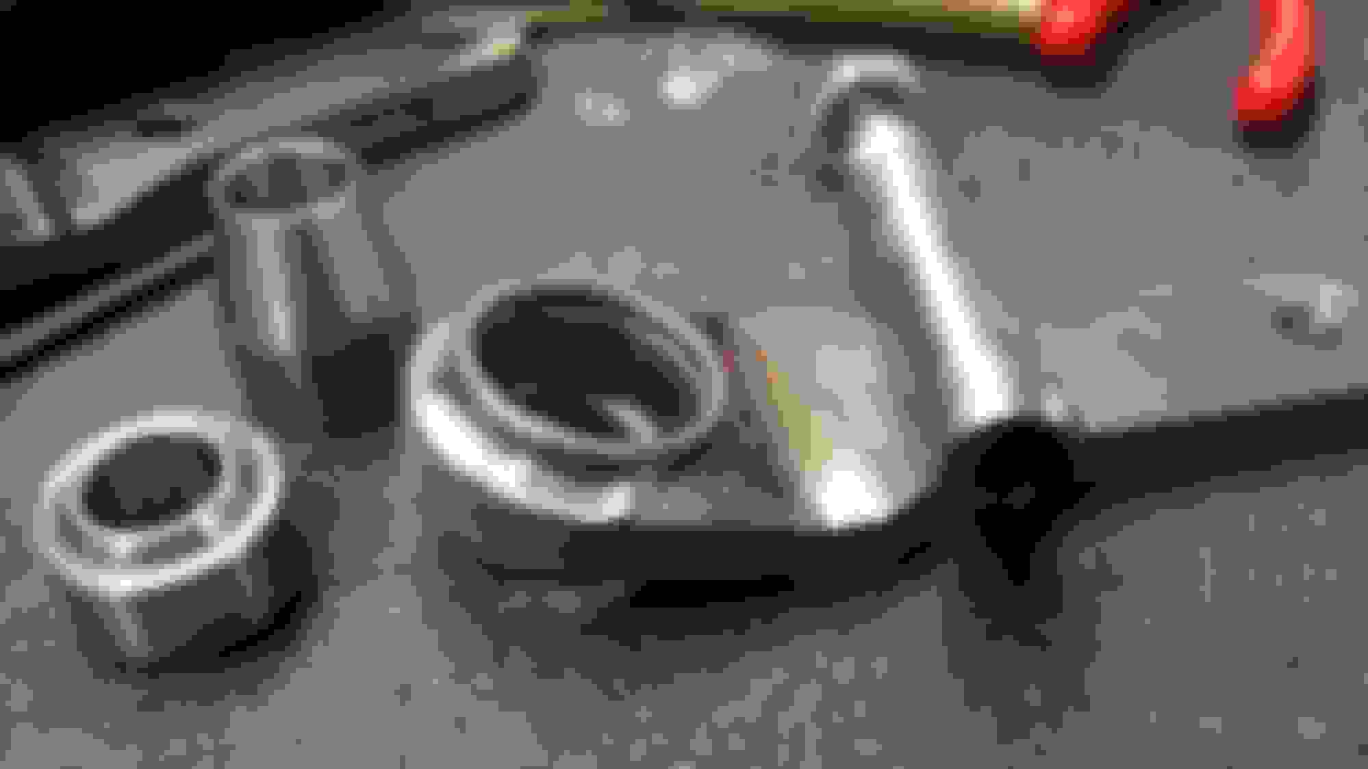
Hey guys, I thought I would share with you guys a roll center correction I made for my car. Sorry I don't have pictures of the steps I took. Just a finished product. I saw another one that was made and designed it similarly.
-1/2 chromoly steel cnc water jet cut and cnc bent body
-tig welded chromoly cups that holds in my replaceable fk spherical bearing
-modified bolt that had been machined for bearing movement and modified to fit factory spindle with no modifications
-stainless steel spacer
Welded with a machined heat sink so the cup wouldn't get too distorted
Car on a 4 post lift. I wonder how it would look without the roll center correction. The picture was taken at a slight slant , so it's hard to see how parallel it is
Sorry for bringing up an old post. But I am about to make a set of roll center adjusters. What size spherical bearing did you use?