When you click on links to various merchants on this site and make a purchase, this can result in this site earning a commission. Affiliate programs and affiliations include, but are not limited to, the eBay Partner Network.
I started a thread in the FD forum that discussed the relevance of the Mileage Sensor in the FC and the Mileage Switch in the FD. My goal was to understand what the switch/sensor affected. Here is the original thread in the FD forum: https://www.rx7club.com/3rd-generati...ensor-1120827/
In short, this is what I uncovered after reading both FC and FD FSMs, and taking cues from DaleClark, mdp, and j9fd3s:
There is a relationship chart between Input and Output Devices that exists in the FC and FD FSMs. One of the input devices happens to be the Mileage Sensor (FC) or Mileage Switch (FD).
A. Reference FC FSM Relationship Chart on Pg F1-76 (N/A):
Mileage Sensor Affects: Fuel Injection Amount, Port Air Solenoid Valve, Solenoid Valve (Switch) [unknown solenoid], Igniter (Trailing & Leading Ignition Timing).
B. Reference FC FSM Relationship Chart on Pg F2-74 (Turbo):
Mileage Sensor #1 Affects: Fuel Injection Amount, Port Air Solenoid Valve, Igniter (Trailing & Leading Ignition Timing).
Mileage Sensor #2 Affects: Fuel Injection Amount, Duty Solenoid Valve (Turbo Boost Pressure), Igniter (Trailing & Leading Ignition Timing). *
* - Mileage Sensor #2 active for the first 600mi (1,000km). Bonus find!
C. Reference FD FSM Relationship Chart on Pg F-182:
Mileage Switch Affects: Secondary Air Bypass, Split Air Bypass, Port Air Bypass, and Relief2 Solenoid Valves
Ultimately, it looks like the mileage switch/sensor affects the car's fuel & emissions in an obscure and minuscule way past 20,000mi. Whatever magic happens inside the ECU will remain a mystery.
I hope this thread sheds some light on an obscure sensor that may not have been previously discussed or known. This info could be useful for anyone who runs a 13B-REW with FD ECU in their FC. One final note, this research was based upon info contained in the 1991 and 1994 workshop manuals.
Cheers,
George
Last edited by Gen2n3; Nov 16, 2017 at 10:38 AM.
Reason: Correction to Item C.
So here's the story. I've been doing electronic repairs on the car. Wanted to get the AC in the FC for the summer, so I had to rebuild the compressor and fan amplifier circuit. Went great, had to replace some electronic components because they were old and decrepit. Good to go on AC. Then I thought I had better check and make sure my car alarm is working properly since my truck was broken into last month. Pulled that computer and found that all the electrolytic caps had barfed everywhere. I pulled the rest of the computers in the car as well, anything that had a cap, so I can just replace them all at once because shipping on tiny electronic parts is worth 3000% the value of the parts.
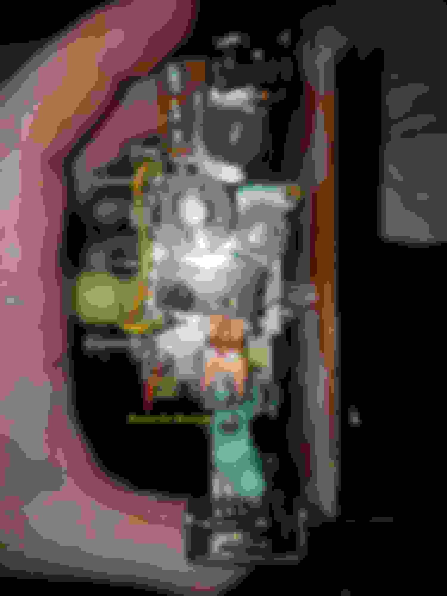
Anyways, had other gremlins to chase as well and ended up going through the gauges. Had to fix a short in the speedo cluster and had a look at the mileage sensors. There are 2 sensors (cammed mechanical switches) for mileage, and they both send a signal to the ECU. The ECU uses signal from these to adjust timing and fuel. According to the FSM, pages F2-77, 78 both sensors are supposed to pass 12v (fully closed, depressed) to the ECU below a specific mileage. In the attached picture, you can see both of them. The top switch is open circuit (tested with mm), and the bottom switch is closed circuit. What difference does this make in fuel delivery, and has anybody fooled with adjusting these things? I was thinking of taking the C-clip off the drive gear for the lower switch (bottom right), removing it, and rotating the cam gear to open the switch. What do you guys think?
Thank you for the post and the photo! IMHO, I wouldn't mess with it because the effect of changing the switches would be negligible to fuel and timing. However, it would be neat to see an exploded view of the gears, cams, and switches. How does that connect to the odometer? Be careful not to mess with the odometer!
More importantly, did you take any photos or catalog your repairs to all those electrical components? It would be a great asset for other forum members to learn from!
Haven't recorded any of the AC stuff. That is already in another post on here. The only difference was I had a bad diode and had to desolder and every single stinking thing on that board to test it and then resolder it. You can't test those components on the board.
I haven't done anything with the other computers/circuits yet. Today was just opening them up, writing down the caps, and closing them. The problems I'm trying to fix is that my cruise control says that it has a short but all the items it says to test are good. Driving me nuts. The other is that my CPU has dead caps. The no beeper thing is nice, but it causes the seatbelt light to go bananas and the car alarm is dead. I figure that this is the way to sort out all the electrical gremlins in one swoop.
I decided to go through and check out the sensor switches on the speedo anyway, just so I understand how they work. Turns out that one of them was bad. The bottom switch should break the circuit when the lever is released, but it doesnt. Easy fix. The third terminal (left) breaks the circuit when the lever is depressed. Gonna rotate the cam wheel and resolder the terminal wire to the next terminal over. Taking pictures.
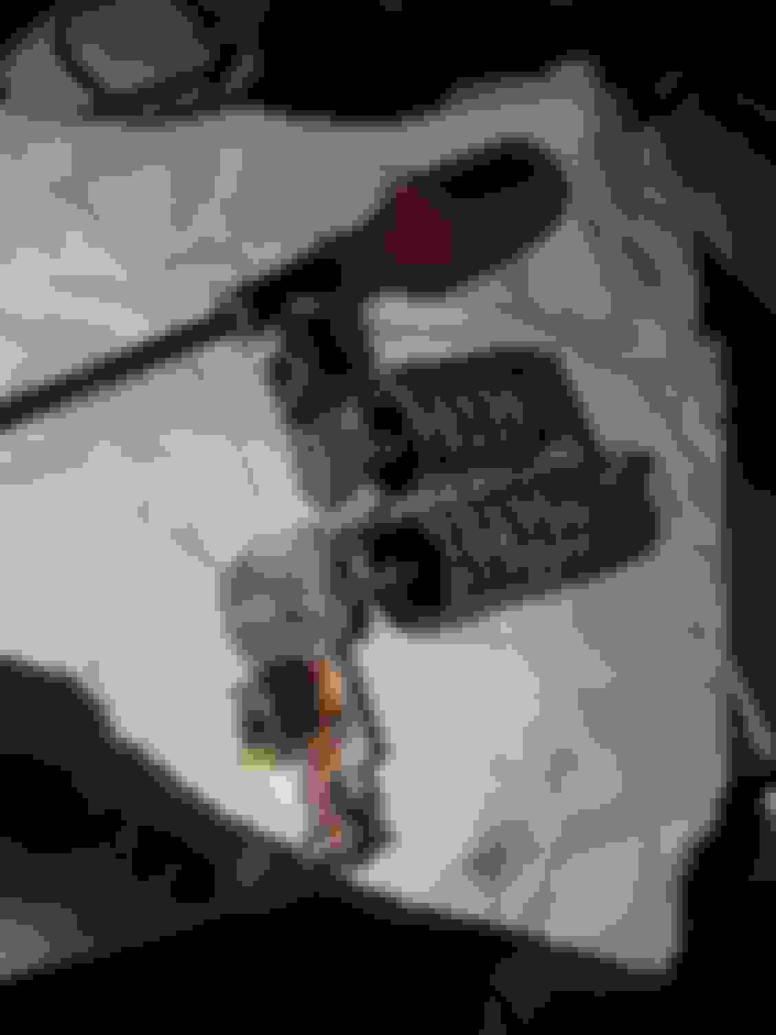
So, to explain, there is a single 12v input on the lower right mounting screw. The metal frame of the speedometer assembly carries the 12v to the sensors The other 3 mounting screws are the outputs for your speed sensor and your two mileage sensors. To fix the one mileage sensor, all I had to do was remove the two screws holding the odometer assembly. Then I could get my 200lb gorilla hands in to resolder the wire output, and switch the cam wheel so that the switch will remain in the open circuit position for the forseeable future (picture 3). I'll have to monkey with it in approximately another 80,000 miles.
I'll take pictures of the other electronic fixes. It would be good if we could get the community to show practical pictures of where circuits go, and how the wiring harnesses are run with good pictures.
I'd suspect its more of just a limit on a physical mechanism. These things can be swapped out, as indicated in page T-41 of the FSM. One of the switches is supposed to stay with the car, but they can both be swapped pretty easily if one is goofed. I'd be curious just how much influence it has over the tune. I suppose a person could put jumpers to the connections at the back of the gauge to close and open the circuits at will. I want to know, but I don't want to bother.
I'd still prefer it over the dash tumors that Mazda puts in their new cars. Wife has one in her car and its hideous. Can't hide it. Big black rectangle occupying 40% of the minimal amount of windshield they give you. Have to have cameras because you can't see out the darn thing... Welp, that's rant No. 1 for the day.
Because I am just looking at mine, here are my 2 cents. Your 12v input is in fact earth/ground, so no voltage should be there. And on an European S5 car the gears of the 600 mile switch (S4 don't have it) look kinda different - in fact they turn the switch on/off EVERY 600 miles. Because of that I like to think that the ECU remembers that value after the first 600 miles and ignores any further cycle (probably the 20k mile switch too)�