
How to Rebuild a Stock HT-18 Turbo & Build a Hybrid

Thread Starter
Joined: Mar 2008
Posts: 8,718
Likes: 6
From: San Diego, CA
How to Rebuild a Stock HT-18 Turbo & Build a Hybrid
Excessive shaft play or smoking? This thread may be for you. I recently rebuilt a stock turbo, and converted it to a T04b hybrid. I'll add on hybrid conversion details later, but I wanted to make a write-up just for rebuilding the stock turbo.
A kit like this one can be used: http://gpopshop.com/products-page/re...e-rebuild-kit/
Tools needed:
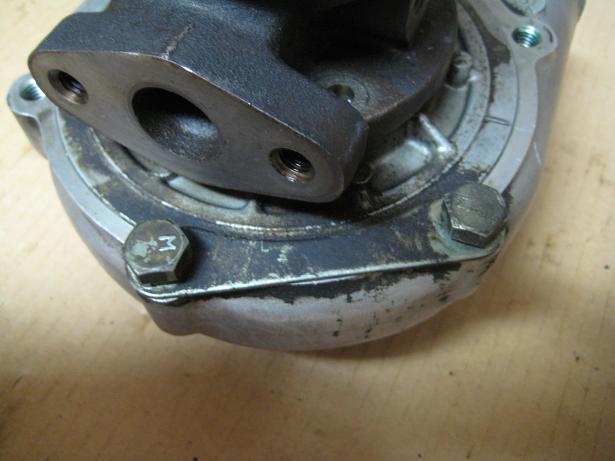
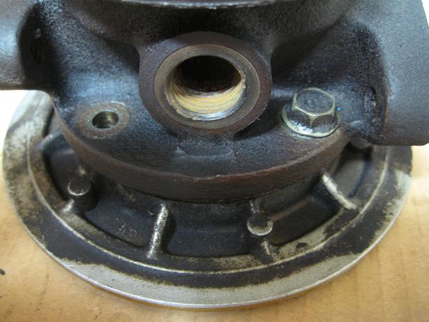
1. Remove the compressor cover and wastegate actuator
Flip the turbo over, and remove the six 13mm bolts. Remove the cir-clip from the actuator rod. The cover will now pop off from the backplate. Before taking it off, make a mark across the two sides to remind you how the cover was clocked.
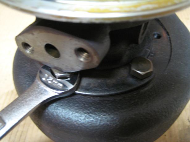
2. Remove the turbine housing
Loosen all six 13mm bolts. There will be two located under the oil feed and return flanges. Loosen these two bolts until they contact the flanges, then alternate between them until they “jack” the CHRA up enough to break free of the housing. Rotate the CHRA to get all of the bolts completely out. Mark across the CHRA and housing to note how it was clocked.
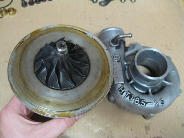
3. Remove the compressor nut and wheel
Make one or more marks across the nut, shaft and compressor wheel. If reusing all of these parts, you can skip rebalancing costs if you reassemble the rotating assembly EXACTLY as it was before. Place a 10mm wrench on the compressor nut, and a �” or 13mm wrench or socket on the turbine side. For this part I’ve heard rumors that excessive lateral force can bend the shaft, so I made sure to hold the tools as close to the top as possible. It should also be noted that the shaft is NOT reverse threaded like some. Once the nut is free, the wheel will come right off. The front portion of the carbon seal will also be able to slide off the shaft at this point.
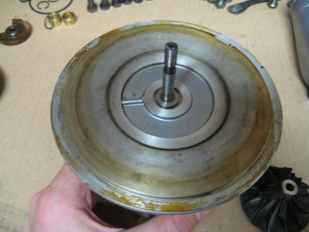
4. Remove the compressor backplate
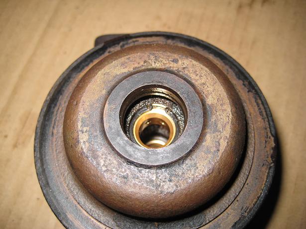
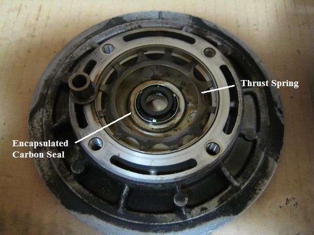
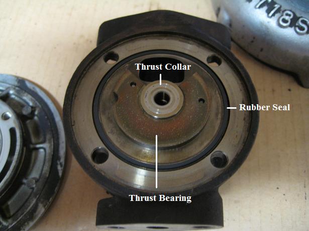
Remove the four 10mm bolts holding the backplate to the CHRA. Pop the backplate off. The thrust spring and carbon seal will be visible on the underside. The thrust bearing and thrust collar will be on the CHRA side, and will now be free to slide off the shaft.
5. Remove the turbine shaft and heatshield
This can be a pain. The piston ring on the shaft will be difficult to break free. I was finally able to get it free by pressing the compressor end of the shaft against a bench while rotating. With the shaft free, the heatshield will also come off.
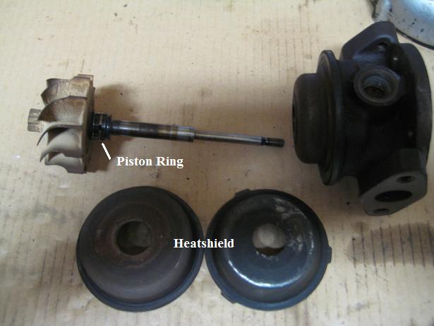
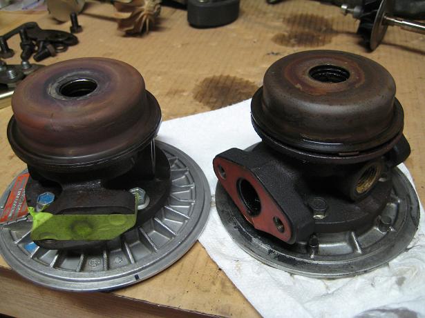
Note that the 2-piece heatshield was apparently only used on early S4 turbos. Late S4 and S5 turbos used a single heatshield. This means that not all S4 and S5 turbine housings are interchangeable. The recess in the early S4 housing is 1mm deeper to accommodate the extra heatshield thickness. If you stick an early S4 CHRA into an S5 housing, it will move the turbine wheel 1mm back from the walls of the housing. This will lead to reduced efficiency.
Left: S5. Right: Early S4.
6. Remove the journal bearings
I bought the smallest snap-ring pliers I could find, but the tips were still too large. So I took a file, and I ground them down until they fit. You can also use a pick/probe to help remove the outer snap-rings from both sides of the CHRA. Once the snap-rings are out, you can use a pick to pull the journal bearings out. If you’re ambitious you can take on the inner snap-rings, but they are not at all easy to access. I left them in place, and just replaced the bearings and outer snap-rings.
7. Reinstall turbine shaft
Replace the piston ring on the end of the turbine shaft, and reinstall. Lube the bearings up with some oil, and press/rotate the shaft back in. Getting the piston ring to compress again is not easy. And don’t forget the heatshield.
8. Replace thrust bearing/collar/spring & carbon seal
Line the thrust bearing/collar up on its locator pins, press the new thrust spring into the underside of the backplate, and replace the rubber seal between the CHRA and backplate. Swap the new carbon seal onto the backplate. Bolt the backplate back onto the CHRA.
9. Reinstall compressor wheel and cover
If not rebalancing, reinstall the compressor wheel and nut so the marks you made line up with the nut torque down. I’ve read it should be torqued down to about 18-20 in-lbs. Place the cover back onto the backplate, and clock it appropriately. Reinstall the clamps, but leave the wastegate actuator off for now.
10. Reinstall turbine housing
Line up the turbine housing with the CHRA, and get all 6 bolts started. Alternate between bolts as you tighten to prevent damaging the turbine wheel. Make sure the housing is clocked as it should be. Reinstall the wastegate actuator.
A kit like this one can be used: http://gpopshop.com/products-page/re...e-rebuild-kit/
Tools needed:
- 10mm wrench / socket
- 13mm or �” wrench / socket
- Rubber Mallet
- 0.038" Snap-ring pliers
- Pick / Probe
1. Remove the compressor cover and wastegate actuator
Flip the turbo over, and remove the six 13mm bolts. Remove the cir-clip from the actuator rod. The cover will now pop off from the backplate. Before taking it off, make a mark across the two sides to remind you how the cover was clocked.
2. Remove the turbine housing
Loosen all six 13mm bolts. There will be two located under the oil feed and return flanges. Loosen these two bolts until they contact the flanges, then alternate between them until they “jack” the CHRA up enough to break free of the housing. Rotate the CHRA to get all of the bolts completely out. Mark across the CHRA and housing to note how it was clocked.
3. Remove the compressor nut and wheel
Make one or more marks across the nut, shaft and compressor wheel. If reusing all of these parts, you can skip rebalancing costs if you reassemble the rotating assembly EXACTLY as it was before. Place a 10mm wrench on the compressor nut, and a �” or 13mm wrench or socket on the turbine side. For this part I’ve heard rumors that excessive lateral force can bend the shaft, so I made sure to hold the tools as close to the top as possible. It should also be noted that the shaft is NOT reverse threaded like some. Once the nut is free, the wheel will come right off. The front portion of the carbon seal will also be able to slide off the shaft at this point.
4. Remove the compressor backplate
Remove the four 10mm bolts holding the backplate to the CHRA. Pop the backplate off. The thrust spring and carbon seal will be visible on the underside. The thrust bearing and thrust collar will be on the CHRA side, and will now be free to slide off the shaft.
5. Remove the turbine shaft and heatshield
This can be a pain. The piston ring on the shaft will be difficult to break free. I was finally able to get it free by pressing the compressor end of the shaft against a bench while rotating. With the shaft free, the heatshield will also come off.
Note that the 2-piece heatshield was apparently only used on early S4 turbos. Late S4 and S5 turbos used a single heatshield. This means that not all S4 and S5 turbine housings are interchangeable. The recess in the early S4 housing is 1mm deeper to accommodate the extra heatshield thickness. If you stick an early S4 CHRA into an S5 housing, it will move the turbine wheel 1mm back from the walls of the housing. This will lead to reduced efficiency.
Left: S5. Right: Early S4.
6. Remove the journal bearings
I bought the smallest snap-ring pliers I could find, but the tips were still too large. So I took a file, and I ground them down until they fit. You can also use a pick/probe to help remove the outer snap-rings from both sides of the CHRA. Once the snap-rings are out, you can use a pick to pull the journal bearings out. If you’re ambitious you can take on the inner snap-rings, but they are not at all easy to access. I left them in place, and just replaced the bearings and outer snap-rings.
7. Reinstall turbine shaft
Replace the piston ring on the end of the turbine shaft, and reinstall. Lube the bearings up with some oil, and press/rotate the shaft back in. Getting the piston ring to compress again is not easy. And don’t forget the heatshield.
8. Replace thrust bearing/collar/spring & carbon seal
Line the thrust bearing/collar up on its locator pins, press the new thrust spring into the underside of the backplate, and replace the rubber seal between the CHRA and backplate. Swap the new carbon seal onto the backplate. Bolt the backplate back onto the CHRA.
9. Reinstall compressor wheel and cover
If not rebalancing, reinstall the compressor wheel and nut so the marks you made line up with the nut torque down. I’ve read it should be torqued down to about 18-20 in-lbs. Place the cover back onto the backplate, and clock it appropriately. Reinstall the clamps, but leave the wastegate actuator off for now.
10. Reinstall turbine housing
Line up the turbine housing with the CHRA, and get all 6 bolts started. Alternate between bolts as you tighten to prevent damaging the turbine wheel. Make sure the housing is clocked as it should be. Reinstall the wastegate actuator.
Last edited by RotaryRocket88; Mar 13, 2012 at 12:17 AM.
Thread Starter
Joined: Mar 2008
Posts: 8,718
Likes: 6
From: San Diego, CA
Hybrids
When building a hybrid turbo, there are 3 main routes that can be taken.
1) Machine the stock compressor housing and backplate to accept a larger compressor wheel. This is what a BNR stage 1 is: a stock turbo with a T04B V-trim wheel.
2) Replace the compressor housing and backplate with T04 versions with a matching compressor wheel. Grinding down one of the "ears" on the new housing will be needed to clear the LIM. A BNR stage 2 is an example of this kind of hybrid. It uses a T04B H-trim compressor and a T04B housing/backplate. Many of the Japanese hybrids use V-trim compressors and a matching housing/backplate.
3) Replace the compressor housing, backplate & compressor wheel, but also exchange the turbine wheel/shaft. This requires machining of the turbine housing to accept the larger turbine. BNR stage 3 and 4 turbos use this approach with 60-1 compressors and P-trim turbines.
Stock HT-18 compressor: 63.0 mm x 43.8 mm (exducer, inducer)
Common T04B Compressors
8 Blade T04B
Garrett PN, exducer x inducer, trim, flow
409179-0021, 70x48.36 mm, 48 trim, S trim (37 lbs/min)
409179-0022, 70x49.50 mm, 50 trim
409179-0023, 70x51.61 mm, 54 trim
409179-0024, 70x54.00 mm, 60 trim, U trim
409179-0025, 70x55.37 mm, 63 trim, V trim (48 lbs/min)
6 blade T04B
409826-0006, 70x48.35 mm, 48 trim
409826-0012, 70x52.85 mm, 57 trim
409826-0014, 70x55.30 mm, 62 trim, V trim (48 lbs/min)
409826-0015, 70x58.40 mm, 70 trim, H trim (49 lbs/min)
Turbonetics 60-1, 76.2x59.0 mm (57 lbs/min)
Turbonetics 62-1 (60 lbs/min)
Common T04E Compressors
40 trim (36 lbs/min)
46 trim (41 lbs/min)
50 trim (47 lbs/min)
54 trim (45 lbs/min) <-- Note: that the 54 trim flows less than the 50 trim
57 trim (49 lbs/min)
60 trim (50 lbs/min)
Also note that T04E compressor covers can hit the lower intake manifold, which makes the T04B route a better choice.
Pictured below is a T04B25 from a European diesel engine. The compressor side has a 0.6 A/R housing and a U-trim wheel. I wanted to find a T04B35, which is the V-trim version of this turbo, but I had to settle on the smaller version. I bought a V-trim wheel and machined the housing to accept the slightly larger wheel. If going route 1 or 3, don't underestimate the potential cost of having someone machine a housing or two. A local shop quoted me ~$200 to do the machining on my compressor cover. Yikes. Some searching for a good deal may become necessary.

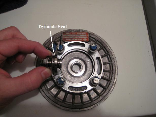
Front Seals
Many turbos will use a dynamic seal rather than the carbon seal found on a stock turbo. A dynamic seal uses a piston ring similar to the one found on the end of the turbine shaft. The compressor backplate and thrust collar on a dynamic seal turbo will be different. Pictured below is the thrust collar and backplate from my T04B25.
Front seal comparison: http://gpopshop.com/garrett-t3-t4-t3t4-kits-2
Modifications
LIM Clearance
Some have reported needing to grind the top right ear on the compressor housing to allow it to clear the LIM. I didn't have to do this, but it was really close. Different castings may require modification. If yours hits, it's going to be because it sticks out too far towards the engine. It should sit right in between the front two intake runners.
Backplate Bolt Pattern
When mating the T04B backplate to my HT-18 CHRA, I ran into an issue with the bolt pattern. The T04B CHRA had slightly larger holes, so the 4 bolts that went into the backplate would line up correctly. I had to bore out the holes on the HT-18 CHRA to match. I don't know if this is a common issue, but it was the case for me.
Oil Drain Line
The oil drain line just barely hit one of the six compressor housing bolts, so I made a spacer out of sheet metal. I used two gaskets, and ended up getting the perfect amount of clearance. And since the stock drain line has a small flex section, it still matched up with the front cover.
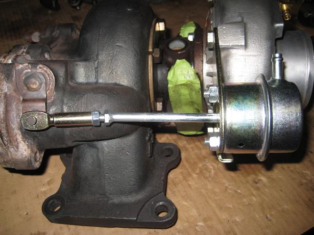
Wastegate Actuator
The stock wastegate actuator won't work without making a custom bracket. I bought a Garrett 6psi actuator and an ebay T04B bracket. The actuator rod ended up being too long, so I had a bolt welded in the middle for use with a threaded end. This allowed me to line things up properly, and it also gives the option to adjust spring tension.
1) Machine the stock compressor housing and backplate to accept a larger compressor wheel. This is what a BNR stage 1 is: a stock turbo with a T04B V-trim wheel.
2) Replace the compressor housing and backplate with T04 versions with a matching compressor wheel. Grinding down one of the "ears" on the new housing will be needed to clear the LIM. A BNR stage 2 is an example of this kind of hybrid. It uses a T04B H-trim compressor and a T04B housing/backplate. Many of the Japanese hybrids use V-trim compressors and a matching housing/backplate.
3) Replace the compressor housing, backplate & compressor wheel, but also exchange the turbine wheel/shaft. This requires machining of the turbine housing to accept the larger turbine. BNR stage 3 and 4 turbos use this approach with 60-1 compressors and P-trim turbines.
Stock HT-18 compressor: 63.0 mm x 43.8 mm (exducer, inducer)
Common T04B Compressors
8 Blade T04B
Garrett PN, exducer x inducer, trim, flow
409179-0021, 70x48.36 mm, 48 trim, S trim (37 lbs/min)
409179-0022, 70x49.50 mm, 50 trim
409179-0023, 70x51.61 mm, 54 trim
409179-0024, 70x54.00 mm, 60 trim, U trim
409179-0025, 70x55.37 mm, 63 trim, V trim (48 lbs/min)
6 blade T04B
409826-0006, 70x48.35 mm, 48 trim
409826-0012, 70x52.85 mm, 57 trim
409826-0014, 70x55.30 mm, 62 trim, V trim (48 lbs/min)
409826-0015, 70x58.40 mm, 70 trim, H trim (49 lbs/min)
Turbonetics 60-1, 76.2x59.0 mm (57 lbs/min)
Turbonetics 62-1 (60 lbs/min)
Common T04E Compressors
40 trim (36 lbs/min)
46 trim (41 lbs/min)
50 trim (47 lbs/min)
54 trim (45 lbs/min) <-- Note: that the 54 trim flows less than the 50 trim
57 trim (49 lbs/min)
60 trim (50 lbs/min)
Also note that T04E compressor covers can hit the lower intake manifold, which makes the T04B route a better choice.
Pictured below is a T04B25 from a European diesel engine. The compressor side has a 0.6 A/R housing and a U-trim wheel. I wanted to find a T04B35, which is the V-trim version of this turbo, but I had to settle on the smaller version. I bought a V-trim wheel and machined the housing to accept the slightly larger wheel. If going route 1 or 3, don't underestimate the potential cost of having someone machine a housing or two. A local shop quoted me ~$200 to do the machining on my compressor cover. Yikes. Some searching for a good deal may become necessary.
Front Seals
Many turbos will use a dynamic seal rather than the carbon seal found on a stock turbo. A dynamic seal uses a piston ring similar to the one found on the end of the turbine shaft. The compressor backplate and thrust collar on a dynamic seal turbo will be different. Pictured below is the thrust collar and backplate from my T04B25.
Front seal comparison: http://gpopshop.com/garrett-t3-t4-t3t4-kits-2
Modifications
LIM Clearance
Some have reported needing to grind the top right ear on the compressor housing to allow it to clear the LIM. I didn't have to do this, but it was really close. Different castings may require modification. If yours hits, it's going to be because it sticks out too far towards the engine. It should sit right in between the front two intake runners.
Backplate Bolt Pattern
When mating the T04B backplate to my HT-18 CHRA, I ran into an issue with the bolt pattern. The T04B CHRA had slightly larger holes, so the 4 bolts that went into the backplate would line up correctly. I had to bore out the holes on the HT-18 CHRA to match. I don't know if this is a common issue, but it was the case for me.
Oil Drain Line
The oil drain line just barely hit one of the six compressor housing bolts, so I made a spacer out of sheet metal. I used two gaskets, and ended up getting the perfect amount of clearance. And since the stock drain line has a small flex section, it still matched up with the front cover.
Wastegate Actuator
The stock wastegate actuator won't work without making a custom bracket. I bought a Garrett 6psi actuator and an ebay T04B bracket. The actuator rod ended up being too long, so I had a bolt welded in the middle for use with a threaded end. This allowed me to line things up properly, and it also gives the option to adjust spring tension.
Last edited by RotaryRocket88; Mar 13, 2012 at 12:09 AM.


Yeah archive this! I can't wait for you to post the hybrid stuff. Also some more mods to turbo's should be put in here. Like porting the WG, different oil mods etc. It would be amazing to have one thread on all the hardware of the stock turbo.
Trending Topics
Maybe I misunderstood your post?
Mods - please add link to this thread to one of the stickies.
Thread Starter
Joined: Mar 2008
Posts: 8,718
Likes: 6
From: San Diego, CA
I'll archive it later on after I finish up. I can add it to the FAQ as well if you guys would like.
For the snap rings, I'll measure them with some calipers later. They're really tiny. I ended up doing more of the removal with picks and a small screw driver than anything. This is a big reason I didn't touch the inner snap rings. It would be very easy to end up dropping one down inside.
For the snap rings, I'll measure them with some calipers later. They're really tiny. I ended up doing more of the removal with picks and a small screw driver than anything. This is a big reason I didn't touch the inner snap rings. It would be very easy to end up dropping one down inside.
Last edited by RotaryRocket88; Mar 12, 2012 at 11:37 PM.
snap ring pliers are the correct tool, i'm not sure what that guy is smoking. get a set of small ones or get a single tool with replaceable bits, makes life easier instead of losing the rings if your kit doesn't come with them. takes about 2 seconds with the correct tool or 30 minutes searching the floor.
i would also add that marking the position of the compressor snail to CHRA and exhaust turbine housing to the CHRA are a good idea to get the positions exactly how they were prior to disassembly. getting everything lined up just right can be a pita on a stock car.
carburetor cleaner is a good degreaser for the aluminum components, do not use an acid based degreaser for them. other simple degreasers like purple power or ZEP(acid/lye based) will work for the bare cast iron CHRA and steel pieces but not on the bronze bushings/thrust bearings(acid will eat away at the surfaces just like aluminum, it's ok on light metals that do not have to have tight tolerances such as for cleaning copper/aluminum crush washers).
Last edited by RotaryEvolution; Jun 21, 2011 at 12:31 PM.
Feel free to remove this post if it's off track. I was going to start a thread asking, but it seems appropriate here.
When I put the compressor housing back on does it need to have any kind of sealant? Both the turbo's I've taken apart as well as the one in this thread have the hardened yellowish substance where the housing meets the compressor backplate. Is that simply residue or an actual sealant?
When I put the compressor housing back on does it need to have any kind of sealant? Both the turbo's I've taken apart as well as the one in this thread have the hardened yellowish substance where the housing meets the compressor backplate. Is that simply residue or an actual sealant?
that is an anaerobic sealant, for best results the housing surfaces should be sealed but it really isn't necessary. if you do use it then i would really suggest doing the noted step i suggested which is to mark all positions of the turbo center section and snails so that it is all lined up properly as the anaerobic seals can start to harden fairly quickly after assembly(anaerobic means it cures in the absence of air, basically during assembly).
http://www.permatex.com/products/Aut...et_Maker_b.htm
without the sealant you will get very small air leaks around the flange.
in all honesty i'm not sure if small leaks are really a bad thing, i have actually seen improvements in turbo spool time without a sacrifice in much horsepower loss from having smaller leaks depending on some setups. just sent off an FD that had stock twins(went single) that made a claimed 380WHP that had about a dozen leaks in the system that have obviously been there since it was dynoed many years ago. in my car for example, the more leaks i fix in the system the slower the turbo spools but does make only a tiny bit more power(but mine not being a good example as i have a VERY restrictive intercooler).
Last edited by RotaryEvolution; Jun 21, 2011 at 01:47 PM.
Thread Starter
Joined: Mar 2008
Posts: 8,718
Likes: 6
From: San Diego, CA
When I put the compressor housing back on does it need to have any kind of sealant? Both the turbo's I've taken apart as well as the one in this thread have the hardened yellowish substance where the housing meets the compressor backplate. Is that simply residue or an actual sealant?
talking head
Joined: Apr 2008
Posts: 2,775
Likes: 15
From: Perth, WA, OZ

Interested to see when you put the t04b wheel on how many threads are sticking out for the compressor nut to grab hold to. While building my t04e 57 trim hybrid, the compressor nut only had about two or three threads to grab on to. The shaft only went about halfway into the nut. Im wondering if the e wheels are "taller" than the b

talking head
Joined: Apr 2008
Posts: 2,775
Likes: 15
From: Perth, WA, OZ
Interested to see when you put the t04b wheel on how many threads are sticking out for the compressor nut to grab hold to. While building my t04e 57 trim hybrid, the compressor nut only had about two or three threads to grab on to. The shaft only went about halfway into the nut. Im wondering if the e wheels are "taller" than the b
,, i think the stock is about 24 mm tall to the inducer
and the t04 b is 26 mm
,, and the E i think is 32 mm
Thread Starter
Joined: Mar 2008
Posts: 8,718
Likes: 6
From: San Diego, CA
Interested to see when you put the t04b wheel on how many threads are sticking out for the compressor nut to grab hold to. While building my t04e 57 trim hybrid, the compressor nut only had about two or three threads to grab on to. The shaft only went about halfway into the nut. Im wondering if the e wheels are "taller" than the b
I can measure the height of the stock compressor and a T04B U-trim later today. But the height of the "nose" of the wheel is what's going to determine if it fits on the shaft. I do know that the height from the base to the inducer fins does vary between trims. The V-trim wheel I have is slightly shorter than the U-trim (to the compressor). This came into play when the compressor cover was machined out.
I don't have any T04E wheels I could measure, and I honestly don't have much information on T04E hybrids. It seems to be much less common.
Thanks. A lot of this info already exists in one place or another, but I figured consolidating it like this would be very helpful.
Last edited by RotaryRocket88; Jun 29, 2011 at 02:06 PM.
I need to buy a scale so i can measure things  i think they are taller, ive read that e's are more efficient in higher boost and i wonder if this is why, cause the housings are very close. Sorry to thread jack, cant wait till the wastegate gets put up.
i think they are taller, ive read that e's are more efficient in higher boost and i wonder if this is why, cause the housings are very close. Sorry to thread jack, cant wait till the wastegate gets put up.
Thread Starter
Joined: Mar 2008
Posts: 8,718
Likes: 6
From: San Diego, CA
I measured the 2 wheels I have available.
Stock compressor from bottom hub to top "nose": 32.2 mm
T04B U-trim bottom to top: 32.2 mm
From the bottom of the exducer to the top of the inducer, the T04B U-trim comes in at 25.8 mm, while the stock wheel comes in at 24 mm.
Stock compressor from bottom hub to top "nose": 32.2 mm
T04B U-trim bottom to top: 32.2 mm
From the bottom of the exducer to the top of the inducer, the T04B U-trim comes in at 25.8 mm, while the stock wheel comes in at 24 mm.