
Help! Vacuume Lines..

1987 Turbo II
i got the fsm diagram, but a couple things don't look right.
1
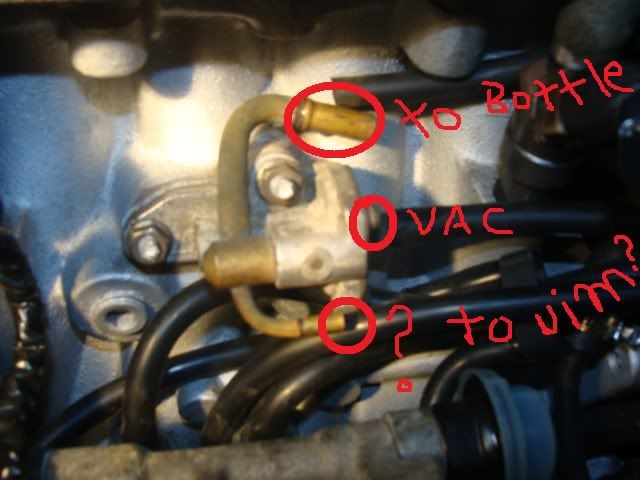
Sub Zero Cold start.... (yes i am keeping it original)
2
From oil filler neck tube, does this connect to the rat nest under it?
3
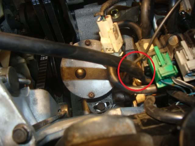
From round vac looking diaphram on rats nest, i hooked this bigger hose to the line comming out of the rotor housing directly below it. is that right?
4
Tube on the rats nest.. kinda missing on the fsm diagrams... im clueless
i got the fsm diagram, but a couple things don't look right.
1
Sub Zero Cold start.... (yes i am keeping it original)
2
From oil filler neck tube, does this connect to the rat nest under it?
3
From round vac looking diaphram on rats nest, i hooked this bigger hose to the line comming out of the rotor housing directly below it. is that right?
4
Tube on the rats nest.. kinda missing on the fsm diagrams... im clueless

Rotary Freak
Joined: Jul 2008
Posts: 1,660
Likes: 2
From: FORT WORTH TEXAS
The nipple at the top of the filler neck get a hose. The hose goes down to about where your circle is and connects to a fairly large pipe. That pipe goes aft and on it aft end gets another hose that connects to the bottom of the purge valves large nipple on its bottom. See jpg out of the FSM.
Rotary Freak
Joined: Jul 2008
Posts: 1,660
Likes: 2
From: FORT WORTH TEXAS
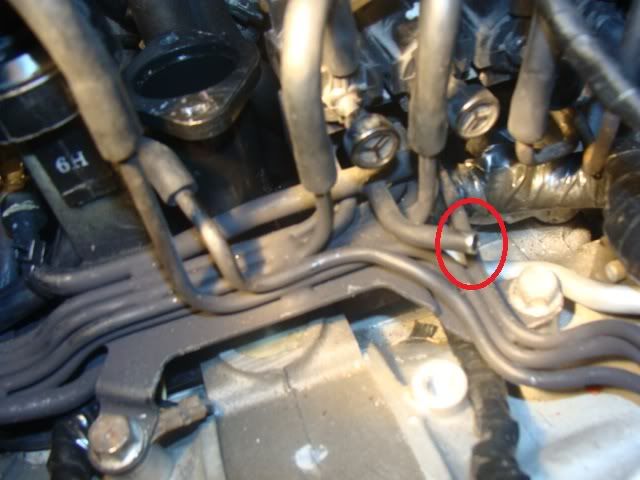
Picture four. That pipe looks similar to the pipe that gets a short hose and connects to another pipe that runs to the right side of the engine and gets a hose on that right side end which connects to a silver checkvalve that plugs into the turbo inlet duct.
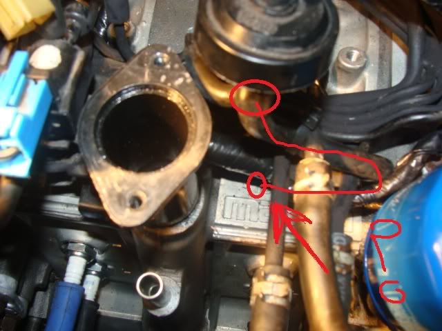
See the green line on the diagram attached. On the aft end of the intermediate housing, below the lowest end of the filler pipe, there is a large nipple . That nipple gets a hose that conencts to the piping. A pipe that is of the same diameter and that pipe goes fwd and ends up just about where you show a red circle around a large pipe. So look at the green line in the diagram and you can see the flow of gases goes over to the checkvalve plugged into the turbo inlet duct.
See the green line on the diagram attached. On the aft end of the intermediate housing, below the lowest end of the filler pipe, there is a large nipple . That nipple gets a hose that conencts to the piping. A pipe that is of the same diameter and that pipe goes fwd and ends up just about where you show a red circle around a large pipe. So look at the green line in the diagram and you can see the flow of gases goes over to the checkvalve plugged into the turbo inlet duct.
got it...
pic 4
that nipple just attaches to a pipe that runs to the check valve by the air inlet for the turbo.
pic 3 runs to the top nipple of the oil filler neck
pic 2 runs to the lower filler neck?
pic 4
that nipple just attaches to a pipe that runs to the check valve by the air inlet for the turbo.
pic 3 runs to the top nipple of the oil filler neck
pic 2 runs to the lower filler neck?
Rotary Freak
Joined: Jul 2008
Posts: 1,660
Likes: 2
From: FORT WORTH TEXAS
There's two/three metal pipes that are welded together that go from the left to the right side. One is a oil pip and the other is the green pipe that gets a hose on the right end that gets a silver checkvalve connected to that hose and the checkvalve gets plugged into the turbo inlet duct.
I THINK pic four ...........that nipple gets a hose and that hose gets connected to a pipe that is installed on the firewall and that pipe runs from right to the left side of the car and gets a hose that goes to the charcoal canister..........yes it's part and parcel of the green line I drew that goes over to the turbo inlet duct/checkvalve.
So pic four should be tied to the large nipple on the aft side of the intermediate housing and also to the pipe that goes to the turbo inlet duct.
About three.................that black round thing is the Purge valve. On it's bottom are two nipples one of which is larger than the other. That large nipple will connect with a hose and that hose gets connected to a pipe and...........somehow that large nipple at the top of the filler tube will connect to that pipe.
See the first jpg I attached called PURGE and you see the nipple on top of the filler tube going to the bottom of the PURGE valve via a pipe if memory serves me. This pipe will run real close to the bottom area of the PURGE valve.
OR look at the jpg I attached called PURGE.See how the GREEN line connects with the nipple on the back of the intermediate housing AND also connects to the charcoal canister located on the right side of the engine bay? Make your run work like that picture. That run of the green lines should NOT include the nipple at the top of the filler tube.
The red line goes to the top of the filler tube and makes it way to the bottom of the purge valve via hoses and tubing. Just blow thur the lines/pipes to verify your connecting to the right tubing. It'll all be large guage metal lines and not the smaller metal lines.
Gotta run now.
Rotary Freak
Joined: Jul 2008
Posts: 1,660
Likes: 2
From: FORT WORTH TEXAS
Tell you what. This is a series five jpg and it's almost the same as series five. So Follow it 'cause it's clearer. I might have made some mistakes in what I wrote above. I'm having a difficult time logging on this site today.
Trending Topics
Thanks HAILERS2...
that last .jpg solved it all. working on new honda's for 9 years made me really rusty on vac lines. everything now is electric. new cars must only have less than 6 in of vac line.
that last .jpg solved it all. working on new honda's for 9 years made me really rusty on vac lines. everything now is electric. new cars must only have less than 6 in of vac line.
