
Break your wiper switch PCB? Here’s a fix

Break your wiper switch PCB? Here’s a fix
I went to repair the failed wiper switch in my vert using the procedures found in many online posts, etc. I was disappointed to find that someone had already tried it on this switch. After removing the relay (which was probably operable), I could tell that the PCB had some copper discs/tubes missing and this was the root cause of the failed repair.
I was able to obtain another failed switch and repair it successfully. But being the stubborn person that I am, I was determined to repair the first switch as well. I figured I had nothing to lose.
On the PCB, 4 of the 6 relay pins need to have continuity on the opposite side of the board. There are tiny copper tubes that connect the two sides of the board. When you solder the pins on the accessible side of the board, the proper continuity is achieved on the opposite side via these tubes. When you “break” your PCB (usually by overheating it), the tiny copper discs on the relay side of the board may break when you remove the faulty relay, or the tiny copper tubes may come out altogether.
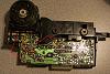
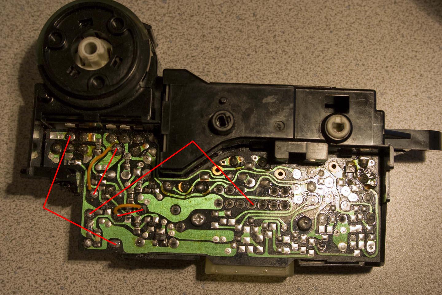
To remedy this, you can jump the orphaned pins to another solder point on the board that is on the same circuit. Using my good wiper switch, and a continuity tester, I was able to map out where these jumper locations could be found. Here is a photo showing where continuity should be if the PCB “tubes” are still intact. If you do not have continuity between any of these, you can jump them. (you can see in the photo where I have two jumper wires attached. After jumping these, the switch works fine)…
I was able to obtain another failed switch and repair it successfully. But being the stubborn person that I am, I was determined to repair the first switch as well. I figured I had nothing to lose.
On the PCB, 4 of the 6 relay pins need to have continuity on the opposite side of the board. There are tiny copper tubes that connect the two sides of the board. When you solder the pins on the accessible side of the board, the proper continuity is achieved on the opposite side via these tubes. When you “break” your PCB (usually by overheating it), the tiny copper discs on the relay side of the board may break when you remove the faulty relay, or the tiny copper tubes may come out altogether.
To remedy this, you can jump the orphaned pins to another solder point on the board that is on the same circuit. Using my good wiper switch, and a continuity tester, I was able to map out where these jumper locations could be found. Here is a photo showing where continuity should be if the PCB “tubes” are still intact. If you do not have continuity between any of these, you can jump them. (you can see in the photo where I have two jumper wires attached. After jumping these, the switch works fine)…


Hey its great to see someone with original initiative to renew some of the mazda electronics.
Id like to ask how you arrived at finding the jumper spots as marked in your photo.
I did continuity checks about a month ago, the same thing, and would find several places
all along the circuit board that showed zero resistance. I tried a few but they didnt work.
I did also follow the traced pathway to other components but didnt work.
How did you decide that your marked ones were the absolute correct ones ?
I will be trying your jumper spots to see if my wiper switch works again. cool.
So with that switch working, I now had a test switch for finding other jumper locations. The switch in the picture did not work, but I had no idea which pins were dead. So by trial and error, looking for continuity on the good switch, I could easily find the pins that were dead on the bad switch.
I poked around on the good switch for a zero resistance location and found one (the longer orange wire in the pic). So I jumped that and tested the switch in my vert. All worked OK. So of the 4 joints that are likely to break (the ones with pathways on the opposite side), I am real certain of two of them. I showed zero resistance on the good switch, and my bad switch worked after jumping them. On the other two, I am only going on results from my multimeter. If someone else has jumped either of those and wants to verify, please post.
Also, just to be sure I wasn't jumping to something that was only "hot" when the wiper switch was turned to a certain setting, I tested the resistance on every setting on the switch (mist, off, lnt, low, high) and the reading never changed.
I guess it is possible that there could be a resistor somewhere in the mix, but my multimeter readings were real consistent.


Joined: Dec 1999
Posts: 7,855
Likes: 517
From: Behind a workbench, repairing FC Electronics.
With a 20 year old board, it's inevitable that the through plating and even the lamination of the copper onto the fiberglass resin will fail. Over time, with vibration and the temperature and humidity changes that a car is exposed to, I even find plenty of cracked or broken traces right in the middle of a trace.
That may be why some of you are not finding a suitable place to jumper to.
I've got a couple methods for repair.
I've found I can get a 30 gauge wire through the hole along side the relay pin. That restores connectivity between the sides of the boards.
I've got a silver based epoxy for repairing damaged traces and pads.
And my main weapon of choice is a RoHS compliant Sn63 substitute solder that contains copper and silver alloys. It's the same **** I used when I used to build radar tracking systems, missile guidance systems, satellite antenna multiplexers, and radio communications parts at an old job... I found that it held up so much better in the Mil-Spec thermal cycling we had to do to the parts.
If it's good enough for soldiers to use to protect their lives, for planes to stay in the air, to keep millions of cell phones online, and to float around in space... It's good enough to clean the road spray offa my windshield, and shine my side marker lights.
Only drawback is it costs over 3x more than standard Sn63 solder. The 3% Silver/0.5% copper variety is mad JDM though and melts at a low enough temperature that I don't burn up too many boards.
Last edited by Pele; Mar 13, 2010 at 03:06 PM.
Full Member
Joined: Aug 2004
Posts: 134
Likes: 0
From: Crosby, Tx
That little white single pole relay that they used is usually the problem with the wipers. I found one with 30 amp contacts, and soldered it with cables about 6 inched long. I had to feed the relay into the dash before replacing the rest of the switch, but my wipers have worked fine ever since. $375 for a new switch is rediculous! I did break down and buy a new window switch though. I had cleaned the contacts to where there was nothing left.
Trending Topics
I can't really tell what you are saying your problem is here, but the steps above are only for a specific situation:
* Front wipers with the "low speed only" symptom
* broken PCB while replacing the relay on the board
This has nothing to do with the convertible top switch (or rear wiper on a coupe), or hazard light switch.
Also, if you have the "low speed only" symptom, you have to replace the relay. Just running jumpers alone will not solve anything. Just wanted to be clear before you wasted any efforts.

HAILERS
Joined: May 2001
Posts: 20,563
Likes: 27
From: FORT WORTH, TEXAS,USA
That little white single pole relay that they used is usually the problem with the wipers. I found one with 30 amp contacts, and soldered it with cables about 6 inched long. I had to feed the relay into the dash before replacing the rest of the switch, but my wipers have worked fine ever since. $375 for a new switch is rediculous! I did break down and buy a new window switch though. I had cleaned the contacts to where there was nothing left.
I've done something similar in the recent past. Instead of removing the faulty relay, I just went to the OTHER side of the relay and soldered on six small ga wires to the base of the original relay.
On the other end of the six new small ga wires, I attached the new factory sized relay from Mouser.
The new wires are long enough to hide the new relay along side the wiper switch and just reinstall the surround and all is well with wipers again.
Doing it this way gets around the possibility of runing the PCB when/if the old relay is relay is removed. Everything stays the same except a new relay is installed. Follow???
https://www.rx7club.com/2nd-generation-specific-1986-1992-17/wiper-switch-rebuild-disaster-833548/
Last edited by daviddeep; Mar 15, 2010 at 12:10 AM. Reason: Added link to my old wiper switch thread
my original cluster only worked on the first speed. so the relay was bad. i found a cluster from an se at a junkyard and i lost my convertible top functionality but the wipers worked on all speeds.
it was a good decision on my part since it was a wet winter here in tx.
now thats its spring i would really like my top to be functional again so what i did is follow your instructions and i installed my original cluster again and now the top works and the wipers work on all speeds.
hooray
it was a good decision on my part since it was a wet winter here in tx.
now thats its spring i would really like my top to be functional again so what i did is follow your instructions and i installed my original cluster again and now the top works and the wipers work on all speeds.
hooray

Plus you now have a coupe switch you can throw out on the FS/WTB forum


Thread
Thread Starter
Forum
Replies
Last Post
Jeff20B
1st Generation Specific (1979-1985)
73
Sep 16, 2018 07:16 PM