
1000 HP 20B Street Car Project

Rotary Freak
Joined: Jan 2002
Posts: 1,643
Likes: 0
From: l.a.
Originally Posted by Red-Rx7
Jim-
I no longer have that turbo setup. The ball-bearings burned themselves out in less than 1800 miles, all highway driven. In researching why this failure occured, it became obvious that the engine airflow was too much at peek (6000 rpm). Ideally, you would want a turbo to support a 70% or higher efficiency at peek. Yet, I was at the 20-25% efficency area at peek, meaning that 75% of the energy the turbo was making was only heating up the air.
I no longer have that turbo setup. The ball-bearings burned themselves out in less than 1800 miles, all highway driven. In researching why this failure occured, it became obvious that the engine airflow was too much at peek (6000 rpm). Ideally, you would want a turbo to support a 70% or higher efficiency at peek. Yet, I was at the 20-25% efficency area at peek, meaning that 75% of the energy the turbo was making was only heating up the air.

Administrative Me
Joined: Feb 2001
Posts: 1,370
Likes: 0
From: Kansas
Originally Posted by fdracer
what the hell are you talking about? compressor efficiency has nothing to do with engine rpm, it's correlated to compressor shaft rpm. the faster you spin the turbo, the more it heats up the compressed air. there is no way you were running at 20-25% efficiency. you have had to boost so much that you would have gone way over the surge limit of the turbo not to mention you would've blown your motor sky high. many sport compact drag cars run 72mm turbos at well over 50lbs. of boost and make around 1000rwhp.
This was my turbo map:

The line drawn was placed there by me, based from my engines lbs/min and pressure ratio. The far right dot, was the used reference, 6000 rpm, for peek lbs/min.
My reference to 20-25% effiency was based on peek cfm. If you were to extend the compressor islands out, the 20-25% was the effiency area where it was operating at peek.
The further to the upward right on the graph, the faster the shaft spins, correct? Take the RPM of the shaft curves, and extend them downwards. This is how it was explained to me, and when extending the curves down, you can see the turbo was spinning between 95,200 and 105,400 rpms. Furthermore, my understanding is that if you divide the amount of power that goes into building pressure by the total power put into the compressor, you get the efficiency of the compressor. The excess amount outside the efficency area, this is the power the turbo is using to heat up the air, vs. used building pressure. Which also would indicate shaft speed and heat failure (if indeed it was 70% of the turbo heating the air).
I am not sure I follow your comparison to other "sport compact cars" running 50lbs of boost either. I understand the aspect that the higher the pressure ratio, the closer to the ceiling of the RPM shaft curves, but there is another part which can get you there as well; engine airflow. I was running no more than 1.95 pressure ratio, so obviously I didn't hit the ceiling of the curve, but what about engine airflow (ie moving to the far right of the graph)?
I look forward to your reply.
Administrative Me
Joined: Feb 2001
Posts: 1,370
Likes: 0
From: Kansas
In re-reading your post, fdracer, I think I understand what you are saying about the sport compact car thingy. Essentially, you were stating about hopping over the surge-limit, which is on the left side of the efficiency islands. This is why you used the very high boost levels as an example, to go over that line.
It seems like you are stating that the only way the turbo will fail via heat is if it went over the surge-limit. Is this what you are saying, as well as regardless of how fast the shaft of the turbo spins or running in a very low efficiency island, it can never overheat the turbo?
It seems like you are stating that the only way the turbo will fail via heat is if it went over the surge-limit. Is this what you are saying, as well as regardless of how fast the shaft of the turbo spins or running in a very low efficiency island, it can never overheat the turbo?

Junior Member
Joined: Sep 2004
Posts: 13
Likes: 0
From: Sweden
Originally Posted by jimlab
Why? Is the air a rotary engine ingests different from the air a V8 ingests?
Have you ever seen the inside of the runners of a Hogan's intake?
Sure it's a great intake manifold... for stock air flow. If they were really so great, though, would things like this exist?
Have you ever seen the inside of the runners of a Hogan's intake?
Sure it's a great intake manifold... for stock air flow. If they were really so great, though, would things like this exist?
2. yes a couple of times yes, A racer friend had a Hogan on one of his racecars..
3. Well it's not always about power.. when you want to go fast you mostly have to sacrifie some of the low end power.. In the long run a race engine will be fkn annoying to use on the street for most ppl. The original engine has to work perfectly and handle lot's of things. I guess both you and me will drop some of the low end tourqe for the upper range. But in my eyes the engine won't work perfectly anymore.. for racing yes but.. it's now adjusted to suit our need for more power.. I know what you mean, but when I look at the Hogan rotary manifold i doubt they are the perfect street/strip performance inlet. Let's say that one of the major companys like GM wants to create the best fkn manifold in the world they will probably be successful.. they can probably built 10000 test engines.. and put billions of $$$ to find the best and the most powerful solution. So there is a reason that the original LS1 manifold look the way it does..
I would change a couple of things on the rotary manifold, but this is my opinion of course. The design of an inlet usually want to distribute the air/fuel mixture as equal as possible between the inlet runners/cylinders
Lot's of plenum designs has been made over the years and the problem has been the distribution between the cylinders.. If you have one single carb on any V8 the length will not b equal for the air to travel. This will make the nearest cylinders to run a little bit rich.. this problem will be worse when the rev goes up coz the air hate to make sharp turns.
I don't have to tell you that's why some racers use two carbs like twin Holley DP:s.. the runners will be almost perfect and as a bonus you can gain more airflow with two carbs and still have some low end torque left.
On a 4 cylinder car you can use twin Weber and you will have a perfect length between all 4 runners that distribute fuel/air to the engine.. But when you put on a plenum you will have some trouble again..
For a couple of years ago i had a plenum similar to your Hogan. The throttlebody has an ovalshape exactly like yours.. This is not a very good thing when you plan to boost the car.. it's very hard to seal it when the boost goes up becoz of the oval shape..
And the next thing is when you have one single throttlebody in one of the ends of the plenum.. the air has to travel to the other side of the plenum and the airspeed/velocity slows down.. that's why you sometimes can see that plenums has a cone shape.. they getting more narrow the more far from the trottlebody to keep the same velocity.. or as near as possible... The rotary manifold has this shape directly after the thottlebody, but i'm not really sure anyway.
i'm not telling you that Hogans can't make inletmanifolds.. But i don't like the rotary inletmanifold from what i can see on the pictures.. I'm not trying to teach you or anybody else what's right or wrong, i just try to share my experiance from this kind of stuff,if u don't agree or don't like it, just ignore it .. that's all

I will stop here coz i will ruin the thread (Sorry Auto Illusions)

And Jimlab.. there are lot's of really good V8 forums for you outthere

Rotary Freak
Joined: Jan 2002
Posts: 1,643
Likes: 0
From: l.a.
you're correct the engine rpm has nothing to do with the turbo efficiency, it's the ve that matters. from your symptoms, it's the rotary's exhaust heat that killed your turbo, not the because turbo was too small. if anything you're not boosting enough to keep the turbo at it's peak efficiency, in which case you can get reversion which is the opposite of compressor surge. as the compressor grabs atmospheric air it compresses it inside the housing, creating a pressure across the compressor wheel. the air itself wants to move down it's pressure gradient, in essence it wants to reverse itself out of the housing and back into the atmosphere where there is low pressure. the only thing preventing that is the compressor wheel constantly sucking in more air. if it's moving too slow, however, the air can reverse upon itself and in the process actually turn the compressor wheel in the opposite direction. in this case a bigger turbo can hurt you more than help you. the key is to get into a good zone with shaft speed.
the example about the other cars is just to prove that you are not overwhelming the turbo and that it can withstand a beating. there are many supras out there that make over 800rwhp w/ this turbo all day long. at your hp level that turbo is still very efficient.
the example about the other cars is just to prove that you are not overwhelming the turbo and that it can withstand a beating. there are many supras out there that make over 800rwhp w/ this turbo all day long. at your hp level that turbo is still very efficient.
Administrative Me
Joined: Feb 2001
Posts: 1,370
Likes: 0
From: Kansas
Originally Posted by fdracer
you're correct the engine rpm has nothing to do with the turbo efficiency, it's the ve that matters. from your symptoms, it's the rotary's exhaust heat that killed your turbo, not the because turbo was too small. if anything you're not boosting enough to keep the turbo at it's peak efficiency, in which case you can get reversion which is the opposite of compressor surge. as the compressor grabs atmospheric air it compresses it inside the housing, creating a pressure across the compressor wheel. the air itself wants to move down it's pressure gradient, in essence it wants to reverse itself out of the housing and back into the atmosphere where there is low pressure. the only thing preventing that is the compressor wheel constantly sucking in more air. if it's moving too slow, however, the air can reverse upon itself and in the process actually turn the compressor wheel in the opposite direction. in this case a bigger turbo can hurt you more than help you. the key is to get into a good zone with shaft speed.
the example about the other cars is just to prove that you are not overwhelming the turbo and that it can withstand a beating. there are many supras out there that make over 800rwhp w/ this turbo all day long. at your hp level that turbo is still very efficient.
the example about the other cars is just to prove that you are not overwhelming the turbo and that it can withstand a beating. there are many supras out there that make over 800rwhp w/ this turbo all day long. at your hp level that turbo is still very efficient.
Thanks for the reply. The basis of the 'turbo being too small', was formed from the compressor map and calculated airflow. If you plot the airflow and pressure ratio, it is way far to the right.
Does the RPM shaft speed extend downwards on the map? Also, I don't think the comparison may be correct, nor my terminology, about other cars and the power they make. When I say too small, it is speaking with regards to peek airflow, and the boost pressure ratio that I run (1.95 ratio, and the calculated 83.64 lbs/min @ peek). If I were to run more boost, then it would bring me closer to the efficency islands. But, because the boost is static, only my airflow is increasing; pushing me way to the right.
Also, going to the larger turbo will lower my RPM shaft speed. Notice on the T72 it was inbetween 95k and 105k; depending on where you draw the lines down from (ie closer to 105k). The new one will be right near 74k shaft speed.
Again, I look forward to your response.
Rotary Freak
Joined: Jan 2002
Posts: 1,643
Likes: 0
From: l.a.
you shouldn't rely on the maps too much. look at keith ta, he had twin t66's which gave him problems cause he didn't boost enough and consequently didn't spin them fast enough. so if your problem is that you're turbo rpms aren't high enough a bigger turbo will exacerbate that. if tiny peashooters like the stock fd turbos or the 20b turbos are efficient at around 10 - 15 lbs., there's no way your turbo is happy at 13. yes, w/ bigger turbos the maps shift down and to the right so it seems like they're happy with low boost, but i've never seen that to be the case. in general the bigger the turbo the more you need to boost. regardless, i think your problem lies elsewhere, not whether your turbo is too big or too small. here's a link to keith's problem.
http://supraforums.com/forum/showthr...hreadid=113673
what they call surge, i call reversion, i think we mean the same thing. anyway it's not the classic surge where you boost too much for the size of your compressor, it's the opposite where you don't boost enough.
http://supraforums.com/forum/showthr...hreadid=113673
what they call surge, i call reversion, i think we mean the same thing. anyway it's not the classic surge where you boost too much for the size of your compressor, it's the opposite where you don't boost enough.

Thread Starter
Senior Member
Joined: Aug 2003
Posts: 703
Likes: 0
From: Moon Twp. Pennsylvania
Here are some pics of the engine back into the car.....
Its too bad the turbo and exhaust manifold are going back to the drawing board to get replaced with something bigger!
I am also working on changing the sub frame this week to chromoly tube style along with making a transmission crossmember and rear diff mount for the new drivetrain!


Its too bad the turbo and exhaust manifold are going back to the drawing board to get replaced with something bigger!
I am also working on changing the sub frame this week to chromoly tube style along with making a transmission crossmember and rear diff mount for the new drivetrain!
Thread Starter
Senior Member
Joined: Aug 2003
Posts: 703
Likes: 0
From: Moon Twp. Pennsylvania
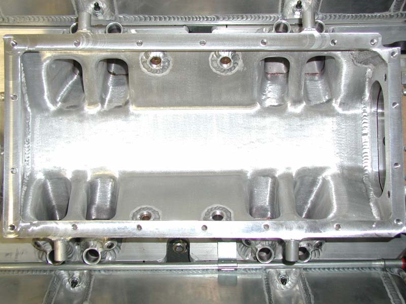
Here are some close ups of the oil pan and sub frame before i replace the sub frame with a chromoly tube style!
I am going to add sway bar mounts to the new sub frame and pick up a couple extra mounting points to tie it all together a litter stronger!

Check out the 4" down pipe!


I am going to add sway bar mounts to the new sub frame and pick up a couple extra mounting points to tie it all together a litter stronger!
Check out the 4" down pipe!

Photo Diety
Joined: Mar 2001
Posts: 2,311
Likes: 0
From: Florida
Explain what I'm looking at with the oil pan/subframe pics...Custom oil pan that goes OVER the steering rack? So the steering rack is in the stock position? How about engine height. Looking at the pics, the custom intake manifold looks pretty darn low giving more hood clearance. Does the engine sit higher or lower than a "typical" 20B conversion? The oil pan sump looks pretty big. How many liters will it hold?
Thread Starter
Senior Member
Joined: Aug 2003
Posts: 703
Likes: 0
From: Moon Twp. Pennsylvania
Originally Posted by rx7tt95
Explain what I'm looking at with the oil pan/subframe pics...Custom oil pan that goes OVER the steering rack?
Originally Posted by rx7tt95
So the steering rack is in the stock position?
Originally Posted by rx7tt95
How about engine height. Looking at the pics, the custom intake manifold looks pretty darn low giving more hood clearance.
Originally Posted by rx7tt95
Does the engine sit higher or lower than a "typical" 20B conversion?
Originally Posted by rx7tt95
The oil pan sump looks pretty big. How many liters will it hold?
Last edited by Auto Illusions; Sep 18, 2004 at 11:00 PM.
Photo Diety
Joined: Mar 2001
Posts: 2,311
Likes: 0
From: Florida
FD Racer, question. VE peak usually coincides with torque peak or where torque and hp cross on a graph. If we pick a VE peak at 6K rpm (theoretical), the engine is still capable of flowing more air with higher rpm. Peak VE is never at rpm max as a general rule in most engines.... So one would have to take into account the increase in CFM with RPM in sizing a turbo. So if Mike's turbine is pushing off the right side of the graph, he's not running into surge. That's the line on the left, sometimes referred to as stall. There are also plenty of larger compressor wheels which are in their range at "paltry" boost levels, it just depends on how they're shaped. Now if the turbo he chose ran shaft speeds beyond what the CHRA was designed for to satisfy boost requirements, he'd still be off the right side of the graph and not the left. If the engine's CFM requirement is to the left of the surge line, the turbo wouldn't work. If you look at the compressor map the surge line clearly has the shaft speed labeled. Shaft speed has more to do with boost levels than supplying CFM which is why it's indicated on the pressure axis, no? The engine would dictate CFM, not the turbo correct? And the number would be static for any given rpm range. I'm sort of working through things in my head as I type so I apologize for the jumbled thoughts. I've always understood that the BB CHRA's were able to tolerate higher shaft speeds than standard bearing center housings. If the bearings burned up, it wasn't due to underuse. I don't see how that's possible? If it's having to spin at a greater rpm, one beyond what it was designed for in order to supply 12psi for his engine, then failure could occur. But I do concur it's hard to believe that 12psi's worth of work did this turbo in unless the compressor just wasn't capable of flowing the CFM's needed by the engine. I know it's a big compressor but again, if you follow the plot out, (and if Mike's CFM numbers are correct), it's off the deep end.
Thread Starter
Senior Member
Joined: Aug 2003
Posts: 703
Likes: 0
From: Moon Twp. Pennsylvania
Here is a closeup of were the steering rack and sub-frame fits within the oil pan!
Please don't pick apart the non polished section as after the pan was polished and did not clear the pickup tube, it had to be cut apart and re-welded to fit!
This is the closest tolerance as the stock oil pan used to hit the pressure fitting coming from the steering rack!

Please don't pick apart the non polished section as after the pan was polished and did not clear the pickup tube, it had to be cut apart and re-welded to fit!
This is the closest tolerance as the stock oil pan used to hit the pressure fitting coming from the steering rack!
Last edited by Auto Illusions; Sep 18, 2004 at 11:28 PM.
Photo Diety
Joined: Mar 2001
Posts: 2,311
Likes: 0
From: Florida
Dude, no worries. I wouldn't be that picky :-) So the front part of the sump is for the oil pickup..how is the oil getting from the back part of the oil pan sump to the front where the pickup is? The steering rack is in the stock location?
Thread Starter
Senior Member
Joined: Aug 2003
Posts: 703
Likes: 0
From: Moon Twp. Pennsylvania
The oil pickup is in the rear as is stock.....The pump is in the front of the engine....
The bubble in the front of the stock pan as well as mine shown is where the pickup tube comes down out of the oil pump and then bends upwards into the block for steering rack clearance (which is how the oil pan can be flush with the bottom of the motor) and then drops back down into the rear of the oil pan were the pick up is located!
The bubble in the front of the stock pan as well as mine shown is where the pickup tube comes down out of the oil pump and then bends upwards into the block for steering rack clearance (which is how the oil pan can be flush with the bottom of the motor) and then drops back down into the rear of the oil pan were the pick up is located!
Thread Starter
Senior Member
Joined: Aug 2003
Posts: 703
Likes: 0
From: Moon Twp. Pennsylvania
In this picture you can see part of the oil pickup tube as it comes down from the oil pump on the left and then curves back up into the block on the right and heads towards the rear of the motor were it drops back down into the oil pan for the pickup!

Thread Starter
Senior Member
Joined: Aug 2003
Posts: 703
Likes: 0
From: Moon Twp. Pennsylvania
Originally Posted by rx7tt95
The steering rack is in the stock location?
Even with no oil pan installed at all, the steering rack would hit the motor....
Look at the stock 13B installed in a 3rd gen.....The steering rack is in front of and above the bottom of the engine were the oil pan bolts up to...
(now imagine extending the enging 6.25" forward to fit the additional rotor housing and center section needed to make it a 3-rotor!)
I don't see how you could install the motor and clear the stock located steering rack without either mounting the motor rearwards 6 inches (unless you use a short PP motor setup with a custom crank and mount the engine rearward 4 inches) or raise the motor mounting position up which causes fittment issues with the stock hood and intake!
Last edited by Auto Illusions; Sep 18, 2004 at 11:42 PM.
Thread Starter
Senior Member
Joined: Aug 2003
Posts: 703
Likes: 0
From: Moon Twp. Pennsylvania
Here is a pictue of the motor installed with the stock oil pan!
The only issue with the fitment was the pressure fitting on the steering rack which could be solved by a little grinding to the fitting and a slight dent in the oil pan to clear!
The new oil pan was made to be tighter so the clearance issue is no longer a problem!

The only issue with the fitment was the pressure fitting on the steering rack which could be solved by a little grinding to the fitting and a slight dent in the oil pan to clear!
The new oil pan was made to be tighter so the clearance issue is no longer a problem!
Last edited by Auto Illusions; Sep 18, 2004 at 11:50 PM.
Administrative Me
Joined: Feb 2001
Posts: 1,370
Likes: 0
From: Kansas
Originally Posted by rx7tt95
FD Racer, question. VE peak usually coincides with torque peak or where torque and hp cross on a graph. If we pick a VE peak at 6K rpm (theoretical), the engine is still capable of flowing more air with higher rpm. Peak VE is never at rpm max as a general rule in most engines.... So one would have to take into account the increase in CFM with RPM in sizing a turbo. So if Mike's turbine is pushing off the right side of the graph, he's not running into surge. That's the line on the left, sometimes referred to as stall. There are also plenty of larger compressor wheels which are in their range at "paltry" boost levels, it just depends on how they're shaped. Now if the turbo he chose ran shaft speeds beyond what the CHRA was designed for to satisfy boost requirements, he'd still be off the right side of the graph and not the left. If the engine's CFM requirement is to the left of the surge line, the turbo wouldn't work. If you look at the compressor map the surge line clearly has the shaft speed labeled. Shaft speed has more to do with boost levels than supplying CFM which is why it's indicated on the pressure axis, no? The engine would dictate CFM, not the turbo correct? And the number would be static for any given rpm range. I'm sort of working through things in my head as I type so I apologize for the jumbled thoughts. I've always understood that the BB CHRA's were able to tolerate higher shaft speeds than standard bearing center housings. If the bearings burned up, it wasn't due to underuse. I don't see how that's possible? If it's having to spin at a greater rpm, one beyond what it was designed for in order to supply 12psi for his engine, then failure could occur. But I do concur it's hard to believe that 12psi's worth of work did this turbo in unless the compressor just wasn't capable of flowing the CFM's needed by the engine. I know it's a big compressor but again, if you follow the plot out, (and if Mike's CFM numbers are correct), it's off the deep end.
And to add more to the story; the actual pressure ratio on the T72 should be shown as 1.8; not 1.95. When the turbo died, I was running 10 psi of boost. Most of the life of the turbo, I was running more than that; until I rewired the wastegate in Indy. Not more than 100 miles later, the turbo died. I am adding 2 psi for pressure drop in the IC/piping/manifold etc. So, (12 + 14.7) / 14.7 = 1.81. I am not sure if I am loosing more or less than 2psi in the ducting, but I would say that the pressure ratio range should be from anywhere of 1.7 to 1.90. So that further pushes down to the right corner; which is away from the general direction of the efficiency islands that go from bottom left to upper right.
Joined: May 2001
Posts: 2,390
Likes: 2
From: San Francisco, CA
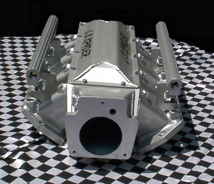
Wow, that looks nice.
What tb are you using?
I'm not sure I like the location of the fuel rails on the manifold though.
Do the vertical runners on the intake need to be so tall?
They look almost as tall as the stock lim and there is tons of room between the engine and uim because of this.
Is it possible to take a section out of the lim to lower the position of the uim to allow you to locate the injector rails on top?
Super Snuggles
Joined: Feb 2001
Posts: 10,091
Likes: 34
From: Redmond, WA
Originally Posted by Red-Rx7
yet the 1.92 is to account for the increase of VE for the rotary.
Administrative Me
Joined: Feb 2001
Posts: 1,370
Likes: 0
From: Kansas
Originally Posted by jimlab
More accurately, to compensate for the fact that a rotary engine's displacement is based on only one rotation of the eccentric shaft vs. two rotations of the crankshaft for a piston engine. The rotary isn't so efficient when you level the playing field.
Super Snuggles
Joined: Feb 2001
Posts: 10,091
Likes: 34
From: Redmond, WA
I think you might be mixing up air flow (cfm) and fuel flow (lbs./hr.).
The rule of thumb for a naturally aspirated piston engine is 2 x intake runner air flow (cfm) at maximum valve lift = maximum horsepower. For an engine with intake ports flowing 330 cfm at maximum lift, maximum horsepower would be about 660. In other words, 1 cfm = 2.06 flywheel horsepower. For a rotary, I'm not sure what the equivalent would be, except that a rotary consumes about twice what its rated displacement would imply.
As far as fuel consumption, a naturally aspirated piston engine has a BSFC (brake specific fuel consumption) of about 0.50, or 0.5 lbs. per hour per horsepower produced. The same 660 horsepower engine would therefore require 330 lbs. of fuel per hour (at WOT). Divide by 8 and divide again by 0.8 (80% duty cycle) and you end up with 51.56 lbs./hr. Therefore, 10 horsepower = 0.78 lbs./hr.
With forced induction or a naturally aspirated rotary, raise BSFC to 0.6-0.7. For a turbocharged rotary, use 0.7-0.8. Convert to cc/min. by multiplying lbs./hr. by 10.2.