
Write up - FC subframe swap (how I did it)

Thread Starter
Joined: Feb 2002
Posts: 8,389
Likes: 120
From: North Jersey
****2025 Update**** – Hi all, I see that this thread comes up pretty readily in a Google search and I still get questions about it from time to time. I have gone back and revised this setup numerous times over the past 15 years. Most of the info below is still a somewhat decent starting point, but does not yield the best result. I have been meaning to update this thread for many years, but never get/take the time to do a proper writeup so I will put some links to threads that are worth reading if you are considering doing this swap yourself. While it is not perfect, I still believe it is a very good option for those who want rack and pinion, bigger brakes, the ability to mount an FC engine without a front cover swap etc etc.
Please take a look at these two threads (there are certainly others as well) as they do a good job pointing out some of the additional things to consider.
https://www.rx7club.com/1st-generati...ments-1153962/
https://www.rx7club.com/1st-generati...sa22c-1171540/
****Original Post Starts here!****
Hey guys, been meaning to do this writeup for a while, but I've just haven't had the time. I've gotton a number of pm's asking for more detail so I figured it was time to make a thread about this. A quick note, when I build a car, or do a project I like to make it look stock, so that if someone who is not familiar with the car were to look at it, they would think that it came that way. With that in mind, I wanted the wheels to line up in the fender well, I did not want the wheels to stick out so far that I needed flares, and I did not want there to be a bunch of easily seen cuts/bends/welds etc. I also did not want to go with coilovers at this time - retaining the stock FB strut/spring/sturt hat etc was important. My point is - there are other ways to do this, this is just how I went about it
First a bit of history. I've wanted to do a FC subframe swap on my T2 FB for many years, but for various reasons (other projects taking up my time etc) I just never go around to it. About this time last year I decided it was time to start getting serious about it and started doing research. Like many of the people pm'ing me I found that the information on here about the swap is very scattered, and many of the build threads were never updated with the end result. It wasn't clear if those people just didn't finish the thread, or if the swap itself had never been completed. I knew there were at least a few people who had finished the swap, but in many cases they were on track only cars, or widebodies or some other setup where it didn't matter as much if it looked stock - it just needed to work. Anyway, after much comparison between the FB parts and FC parts, it became obvious that this was going to work, and work well, so earlier this year (end of March, early April) I went ahead and started wrenching. The end result is exactly what I wanted, you get an easy way to mount the FC engine/steering/brakes and the way I did it, you still retain the abilty to use FB shocks and springs (I already had a good set of Eibach springs and Tokico blues) The wheels don't stick out of the fenders (although the track width is wider than the FB, they don't rub) and other than a few welds that you wouldn't notice unless you were really looking, it looks like it belongs there!
Ok, onto the pics and info. Just a note, this is not intended to be a step by step writeup. If you are planning to do this work then you should already be familiar with how to take the front end of an FB apart, and should be able to cut/weld/modify things. I'm really just showing how I went about the swap, and to give you guys some ideas on how to go about it. Again, there are other ways of doing this, but this is how I went about it
Pffew this is a lot of typing lol.
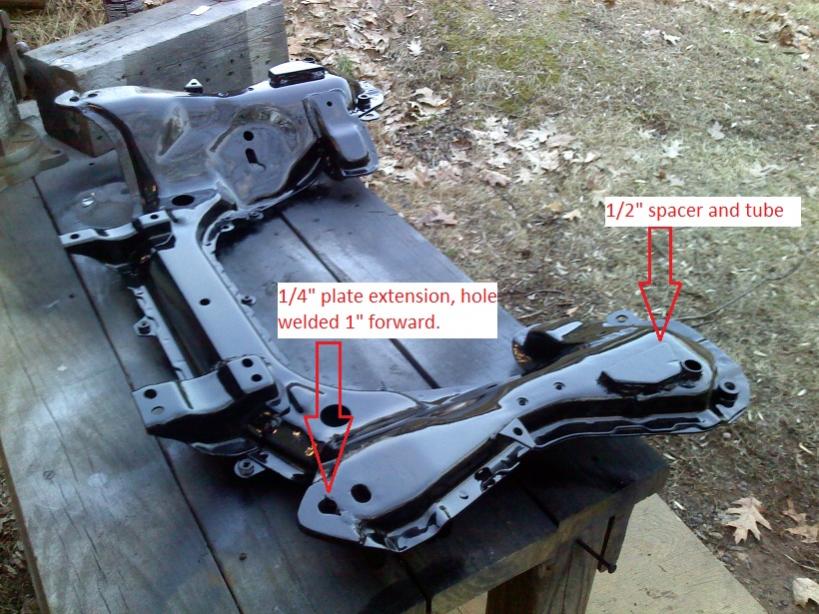
Ok, we'll start with the subframe (good place to start eh? lol) The Subframe needs to be moved back 1 inch. If you were to bolt it up using the existing front hole in the subframe and existing front stud on the FB it will sit too far forward and the wheel will look silly and rub the fender well. Seems that many guys on here just remove all 4 studs from the FB and replace them with bolts in the correct spot. While there is no way to get around the need for a new bolt or stud for the rear of the subframe, you can use the existing front stud if you modify the subframe itself. Again going with my theme of making it look stock, I wanted to keep the modifications to the FB as minimal as possible, this means keeping the front stud. So, to get the subframe moved back the 1 inch it needs to be, I simply drilled a new hole 1" forward on the FC subframe. Now if you look at a FC subframe you'll see that this is dangerously close to the front edge of the frame itself. So once I drilled the hole I made a new extension (whatever you want to call it) out of 1/4" steel that extends the subframe forward and reinforces the whole area. I also made a similar tab out of 1/8" steel to go on the bottom to level out the whole area (the front of the subframe has a stamped curve to it, hopefully the pics make this clearer) The end result is a very solid section of metal, and with some careful grinding and welding it smoothed out to the point that it almost looks stock.
The rear needs some work as well, If looking at the car from the side, the FB frame rails are straight, where the FC ones get thicker and dip down in the back near the firewall, and as a result the FC's subframe is not level (if you look at the subframe from the side its not flat across the top). You will need to construct some large spacers around the rear mounting holes on the FC subframe so that the subframe is level when bolted into the FB. There is some debate on here about how large that spacer needs to be. My initial measurements came up with 1/2", which is what I went with, but if I were to do it again I'd go with 5/8". The 1/2" spacer has worked out fine, but in reality it should be a bit taller. I know Peejay went with a 1" spacer and said it sits flush in his FB, not sure why there is such a difference between our two FB bodies, but either way, whatever gets the thing in there level is what you should make Also, Peejay welded his spacer to the body itself, I welded mine to the subframe, again I wanted to keep the FB body as untouched as possible. (within reason obviously)
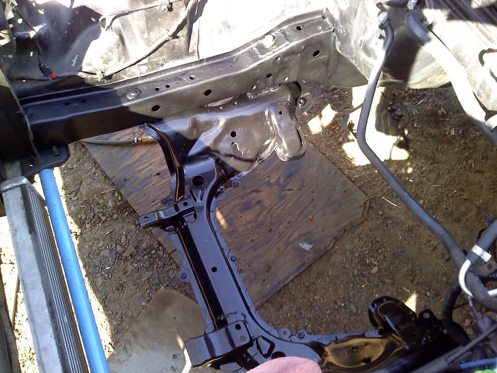
Once you have all the above work done to the subframe then its time to do some work on the FB's body. If you're going the same route as I did then you will leave the front FB stud in there, and just remove the rear stud. It's just held in with a few welds, cut them and out it comes. You will then need to get out of a set of duckbill pliers, or a hammer and dolly, or just a hammer and a block of wood, whatever you prefer, and do some bending on the pinchweld along the bottom of the FB's frame rail. You will see in the pics where you need to bend, its just a few spots around where the FC subframe bows out, nothing major. Once those areas are bent you can put the FC subframe on the FB's front studs and hold it there with some nuts (be sure to support the rear with some stands or something as well) If you've done your measuring correctly then it should be lined up and sitting in there correctly. Make sure you measure constantly throughout this process to make sure its sitting in there straight and level! Now you can go ahead and mark where you're going to drill for the rear studs/bolts. Be warned, the new rear studs go basically right through the middle of where the stock FB steering box and idler arm go, there are multiple layers of metal and some tubes to support the idler arm/steering box. How you go about drilling these holes is up to you, just be careful not to go balistic and damage a bunch of surround metal or yourself! I only say that because I was using an incredibly powerful corded drill with a unibit to get through the FB box's support tube, it caught and almost broke my wrist from the force lol, so be careful. Anyway, once the hole is drilled where you want it, its time to reinforce the area. I used 8" long 1/2" grade 8 bolts, so get some thick tubing that those bolts will slide through (I found it at Lowes) and some 1/8" steel plate. You basically want to have the tube go through the frame rail to keep it from collapsing when you tighten the bolt, and you want the 1/8" plate on the top of the frame rail to support that tube, and keep the sheet metal from deforming. Once that is all weded together and painted to prevent rusting go ahead and bolt the subframe in! Double check your measurements etc and thats literally it! Now it's time to put the rest of the puzzle pieces in place....
I don't have a pic offhand of the bent sections of the frame rail, I will get one and post it, its very simple though so don't sweat that part
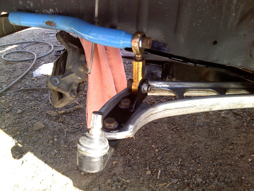
Ok so the subframe is in, now what? Well, the FC control arms, spindles, hubs, brakes (the FB master cylinder runs the T2 brakes just fine, and presumably the NA FC brakes as well) and steering rack are all just bolt in items. Obviously now is a good time to replace worn parts like ball joints tie rods and bushings, sandblast and paint things etc, but thats entirely up to you. A quick note, the S4 (86-88) control arms are preferable because they have replaceable ball joints, but the S5's will work as well. Also, if you're running a re-speed sway bar, which already has solid heim jointed links then all you need to do is make a simple brakcet to attach it to the control arm. If you want to run the FC sway bar then you will need to make some way to mount it to the FB body. I did not go this route (I used the re-speed bar) so I'm not 100% familiar with the mods needed, however the "legs" on the FC sway bar are shorter than that of an FB bar, so it needs to be mounted closer to the subframe to work. I know its been done on several other swaps, and is probably just a matter of drilling and reinforcing a few holes in the FB frame rail and bolting it in. So once all that is taken care of, you have the steering colum and the strut assemblies left to build, and you guessed it, more cutting and welding!
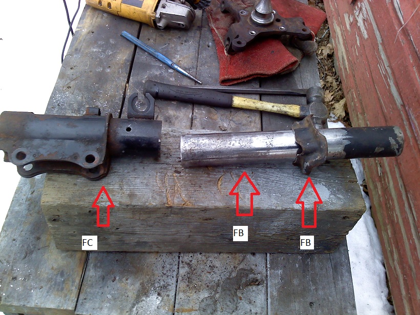
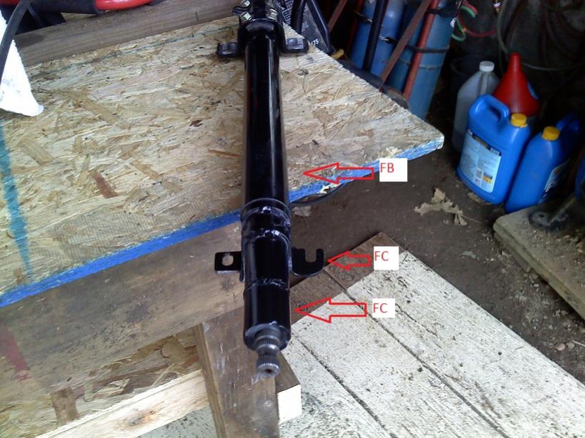
Both the strut assemblies and steering column are similar in that they use FB "upper" parts and FC "lower" parts. There are many ways to go about the suspension, but what I did was take a set of old blown FC shocks, and cut pretty much right below the spring perch. Once you cut all the way around the strut itself will come out and you're left with basically a tube with mounting ears on it. Now take a set of FB spindles and CAREFULLY cut the spring perch off. You just want ot cut the welds, do not cut into the strut tube itself! You want to use both the spring perch and strut tube so don't damage either of these parts. Once the spring perch is off grind the rest of the weld smooth on the strut tube so that the perch can slide past where it used to sit. Next cut the spindle portion off so that you're left with just the tube part of the FB assembly. Conveniently the inner diameter of the FC tube you have, and the outter diameter of the FB tube are the same so they slide together nicely, almost as if it was made for this lol. Basically what you want is the tube to be the same height as the FB's original one (so the FB strut insert will go in correctly) and the spring perch to be the same distance from the middle of the spindle (so the bottom of the spring is the same distance to the middle of the FC spindle, as it was to the middle of the FB spindle) this ensures you have the same ride height you did before. Once all that is figured out then you just weld it all together. I drilled a few holes in the side of the FC tube so I could do some rosette welds, along with the bead I ran along the top, just to give it some extra strength. The end result is a FB strut/spring/spring perch/strut top with the mounting ears to bolt it to the FC spindle. There are other ways to do this obviously, but I'm very happy with the result!
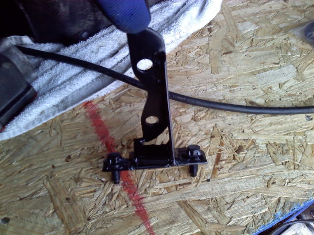
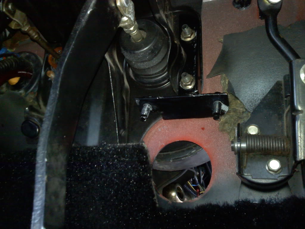
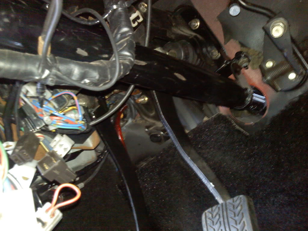
The steering column: You will be using mostly FB parts for this, the FB steering tube/support and the upper half of the FB steering column (you just drill out the plastic shear pins and leave the lower half of the column in the stock box and toss it) You will then need the lower half of an FC steering column (again held with similar shear pins) as well as a short section of the FC's steering column tube with its carrier bearing at the bottom. The FB and FC columns are almost the same size, but not quite close enough to just slide right together (can't be too easy now can it lol) so you will need to take a bit of material off the FC's lower column so that it slides into the FB upper. I used a dull flap wheel on a angle grinder (dull so that i didn't take too much off at a time) and just slowly ground away until it was right. I decided to that there is enough collapsable stuff built into this system that I didn't need to bother making the column collapsible (if you want to, go right ahead) so I just welded the two halves together. Once the column is one piece (be sure to measure 3 or 10 times before welding lol) then you put it into the FB upper and weld the FC lower bearing and its tube to the FB part. They are the same diameter luckily so its not difficult. The only thing left at this point is making a way to hold the bottom of the column in the car. If you have an 84/85 then there is a reinforcment plate around the hole in the firewall that the colulmn goes through, it wouldn't take much to make a small brakcet off two of these studs. If you're doing this on a 83 or older (like me) then you need to get more creative. I made a bracket that goes on two of the brake booster studs, and used the bracket off the bottom of the FC column, to bolt it all together.
Hopefully that answers some of the questions you guys have about this swap, and gives some alternate methods on how to go about doing it. I completed this swap in the beginning of April and have put several thousand miles on it already and so far no issues at all! Other than the pair of 8" long 1/2" grade 8 bolts and the few pieces of flat stock and tubing needed to reinforce the frame, everything comes from the FC donor car. If everything from the FC is usable then you really don't need to buy much. In my case I spent some time sandblasting and painting the parts, and replaced the bushings, ball joints, tie rod ends and tie rod boots. Otherwise it was all stuff I had. In the end I spent less than $400. I also chose to use a 15:1 rack and depowered it, there is a thread in the FC section on how to properly do this, it involved taking the rack completely apart, removing a bunch of seals and running a few welds on the pinion shaft.
Any questions, fire away!
Sean
Please take a look at these two threads (there are certainly others as well) as they do a good job pointing out some of the additional things to consider.
https://www.rx7club.com/1st-generati...ments-1153962/
https://www.rx7club.com/1st-generati...sa22c-1171540/
****Original Post Starts here!****
Hey guys, been meaning to do this writeup for a while, but I've just haven't had the time. I've gotton a number of pm's asking for more detail so I figured it was time to make a thread about this. A quick note, when I build a car, or do a project I like to make it look stock, so that if someone who is not familiar with the car were to look at it, they would think that it came that way. With that in mind, I wanted the wheels to line up in the fender well, I did not want the wheels to stick out so far that I needed flares, and I did not want there to be a bunch of easily seen cuts/bends/welds etc. I also did not want to go with coilovers at this time - retaining the stock FB strut/spring/sturt hat etc was important. My point is - there are other ways to do this, this is just how I went about it
First a bit of history. I've wanted to do a FC subframe swap on my T2 FB for many years, but for various reasons (other projects taking up my time etc) I just never go around to it. About this time last year I decided it was time to start getting serious about it and started doing research. Like many of the people pm'ing me I found that the information on here about the swap is very scattered, and many of the build threads were never updated with the end result. It wasn't clear if those people just didn't finish the thread, or if the swap itself had never been completed. I knew there were at least a few people who had finished the swap, but in many cases they were on track only cars, or widebodies or some other setup where it didn't matter as much if it looked stock - it just needed to work. Anyway, after much comparison between the FB parts and FC parts, it became obvious that this was going to work, and work well, so earlier this year (end of March, early April) I went ahead and started wrenching. The end result is exactly what I wanted, you get an easy way to mount the FC engine/steering/brakes and the way I did it, you still retain the abilty to use FB shocks and springs (I already had a good set of Eibach springs and Tokico blues) The wheels don't stick out of the fenders (although the track width is wider than the FB, they don't rub) and other than a few welds that you wouldn't notice unless you were really looking, it looks like it belongs there!
Ok, onto the pics and info. Just a note, this is not intended to be a step by step writeup. If you are planning to do this work then you should already be familiar with how to take the front end of an FB apart, and should be able to cut/weld/modify things. I'm really just showing how I went about the swap, and to give you guys some ideas on how to go about it. Again, there are other ways of doing this, but this is how I went about it
Pffew this is a lot of typing lol.
Ok, we'll start with the subframe (good place to start eh? lol) The Subframe needs to be moved back 1 inch. If you were to bolt it up using the existing front hole in the subframe and existing front stud on the FB it will sit too far forward and the wheel will look silly and rub the fender well. Seems that many guys on here just remove all 4 studs from the FB and replace them with bolts in the correct spot. While there is no way to get around the need for a new bolt or stud for the rear of the subframe, you can use the existing front stud if you modify the subframe itself. Again going with my theme of making it look stock, I wanted to keep the modifications to the FB as minimal as possible, this means keeping the front stud. So, to get the subframe moved back the 1 inch it needs to be, I simply drilled a new hole 1" forward on the FC subframe. Now if you look at a FC subframe you'll see that this is dangerously close to the front edge of the frame itself. So once I drilled the hole I made a new extension (whatever you want to call it) out of 1/4" steel that extends the subframe forward and reinforces the whole area. I also made a similar tab out of 1/8" steel to go on the bottom to level out the whole area (the front of the subframe has a stamped curve to it, hopefully the pics make this clearer) The end result is a very solid section of metal, and with some careful grinding and welding it smoothed out to the point that it almost looks stock.
The rear needs some work as well, If looking at the car from the side, the FB frame rails are straight, where the FC ones get thicker and dip down in the back near the firewall, and as a result the FC's subframe is not level (if you look at the subframe from the side its not flat across the top). You will need to construct some large spacers around the rear mounting holes on the FC subframe so that the subframe is level when bolted into the FB. There is some debate on here about how large that spacer needs to be. My initial measurements came up with 1/2", which is what I went with, but if I were to do it again I'd go with 5/8". The 1/2" spacer has worked out fine, but in reality it should be a bit taller. I know Peejay went with a 1" spacer and said it sits flush in his FB, not sure why there is such a difference between our two FB bodies, but either way, whatever gets the thing in there level is what you should make
Also, Peejay welded his spacer to the body itself, I welded mine to the subframe, again I wanted to keep the FB body as untouched as possible. (within reason obviously)Once you have all the above work done to the subframe then its time to do some work on the FB's body. If you're going the same route as I did then you will leave the front FB stud in there, and just remove the rear stud. It's just held in with a few welds, cut them and out it comes. You will then need to get out of a set of duckbill pliers, or a hammer and dolly, or just a hammer and a block of wood, whatever you prefer, and do some bending on the pinchweld along the bottom of the FB's frame rail. You will see in the pics where you need to bend, its just a few spots around where the FC subframe bows out, nothing major. Once those areas are bent you can put the FC subframe on the FB's front studs and hold it there with some nuts (be sure to support the rear with some stands or something as well) If you've done your measuring correctly then it should be lined up and sitting in there correctly. Make sure you measure constantly throughout this process to make sure its sitting in there straight and level! Now you can go ahead and mark where you're going to drill for the rear studs/bolts. Be warned, the new rear studs go basically right through the middle of where the stock FB steering box and idler arm go, there are multiple layers of metal and some tubes to support the idler arm/steering box. How you go about drilling these holes is up to you, just be careful not to go balistic and damage a bunch of surround metal or yourself! I only say that because I was using an incredibly powerful corded drill with a unibit to get through the FB box's support tube, it caught and almost broke my wrist from the force lol, so be careful. Anyway, once the hole is drilled where you want it, its time to reinforce the area. I used 8" long 1/2" grade 8 bolts, so get some thick tubing that those bolts will slide through (I found it at Lowes) and some 1/8" steel plate. You basically want to have the tube go through the frame rail to keep it from collapsing when you tighten the bolt, and you want the 1/8" plate on the top of the frame rail to support that tube, and keep the sheet metal from deforming. Once that is all weded together and painted to prevent rusting go ahead and bolt the subframe in! Double check your measurements etc and thats literally it! Now it's time to put the rest of the puzzle pieces in place....
I don't have a pic offhand of the bent sections of the frame rail, I will get one and post it, its very simple though so don't sweat that part
Ok so the subframe is in, now what? Well, the FC control arms, spindles, hubs, brakes (the FB master cylinder runs the T2 brakes just fine, and presumably the NA FC brakes as well) and steering rack are all just bolt in items. Obviously now is a good time to replace worn parts like ball joints tie rods and bushings, sandblast and paint things etc, but thats entirely up to you. A quick note, the S4 (86-88) control arms are preferable because they have replaceable ball joints, but the S5's will work as well. Also, if you're running a re-speed sway bar, which already has solid heim jointed links then all you need to do is make a simple brakcet to attach it to the control arm. If you want to run the FC sway bar then you will need to make some way to mount it to the FB body. I did not go this route (I used the re-speed bar) so I'm not 100% familiar with the mods needed, however the "legs" on the FC sway bar are shorter than that of an FB bar, so it needs to be mounted closer to the subframe to work. I know its been done on several other swaps, and is probably just a matter of drilling and reinforcing a few holes in the FB frame rail and bolting it in. So once all that is taken care of, you have the steering colum and the strut assemblies left to build, and you guessed it, more cutting and welding!
Both the strut assemblies and steering column are similar in that they use FB "upper" parts and FC "lower" parts. There are many ways to go about the suspension, but what I did was take a set of old blown FC shocks, and cut pretty much right below the spring perch. Once you cut all the way around the strut itself will come out and you're left with basically a tube with mounting ears on it. Now take a set of FB spindles and CAREFULLY cut the spring perch off. You just want ot cut the welds, do not cut into the strut tube itself! You want to use both the spring perch and strut tube so don't damage either of these parts. Once the spring perch is off grind the rest of the weld smooth on the strut tube so that the perch can slide past where it used to sit. Next cut the spindle portion off so that you're left with just the tube part of the FB assembly. Conveniently the inner diameter of the FC tube you have, and the outter diameter of the FB tube are the same so they slide together nicely, almost as if it was made for this lol. Basically what you want is the tube to be the same height as the FB's original one (so the FB strut insert will go in correctly) and the spring perch to be the same distance from the middle of the spindle (so the bottom of the spring is the same distance to the middle of the FC spindle, as it was to the middle of the FB spindle) this ensures you have the same ride height you did before. Once all that is figured out then you just weld it all together. I drilled a few holes in the side of the FC tube so I could do some rosette welds, along with the bead I ran along the top, just to give it some extra strength. The end result is a FB strut/spring/spring perch/strut top with the mounting ears to bolt it to the FC spindle. There are other ways to do this obviously, but I'm very happy with the result!
The steering column: You will be using mostly FB parts for this, the FB steering tube/support and the upper half of the FB steering column (you just drill out the plastic shear pins and leave the lower half of the column in the stock box and toss it) You will then need the lower half of an FC steering column (again held with similar shear pins) as well as a short section of the FC's steering column tube with its carrier bearing at the bottom. The FB and FC columns are almost the same size, but not quite close enough to just slide right together (can't be too easy now can it lol) so you will need to take a bit of material off the FC's lower column so that it slides into the FB upper. I used a dull flap wheel on a angle grinder (dull so that i didn't take too much off at a time) and just slowly ground away until it was right. I decided to that there is enough collapsable stuff built into this system that I didn't need to bother making the column collapsible (if you want to, go right ahead) so I just welded the two halves together. Once the column is one piece (be sure to measure 3 or 10 times before welding lol) then you put it into the FB upper and weld the FC lower bearing and its tube to the FB part. They are the same diameter luckily so its not difficult. The only thing left at this point is making a way to hold the bottom of the column in the car. If you have an 84/85 then there is a reinforcment plate around the hole in the firewall that the colulmn goes through, it wouldn't take much to make a small brakcet off two of these studs. If you're doing this on a 83 or older (like me) then you need to get more creative. I made a bracket that goes on two of the brake booster studs, and used the bracket off the bottom of the FC column, to bolt it all together.
Hopefully that answers some of the questions you guys have about this swap, and gives some alternate methods on how to go about doing it. I completed this swap in the beginning of April and have put several thousand miles on it already and so far no issues at all! Other than the pair of 8" long 1/2" grade 8 bolts and the few pieces of flat stock and tubing needed to reinforce the frame, everything comes from the FC donor car. If everything from the FC is usable then you really don't need to buy much. In my case I spent some time sandblasting and painting the parts, and replaced the bushings, ball joints, tie rod ends and tie rod boots. Otherwise it was all stuff I had. In the end I spent less than $400. I also chose to use a 15:1 rack and depowered it, there is a thread in the FC section on how to properly do this, it involved taking the rack completely apart, removing a bunch of seals and running a few welds on the pinion shaft.
Any questions, fire away!
Sean
Last edited by 82transam; Oct 21, 2025 at 06:42 AM. Reason: 2025 update
Awesome write up!
If you could post the a link to the info on the de-powering I would appreciate it.
Also what wheels are you running and how are you compensating for the difference in width front to rear?
If you could post the a link to the info on the de-powering I would appreciate it.
Also what wheels are you running and how are you compensating for the difference in width front to rear?
Old [Sch|F]ool


Joined: May 2001
Posts: 12,876
Likes: 575
From: Cleveland, Ohio, USA
Simple. Takes longer to say than to do.
There's another way where you disassemble the rack and physically damage or remove the piston, but this is overkill.
Also what wheels are you running and how are you compensating for the difference in width front to rear?
Thread Starter
Joined: Feb 2002
Posts: 8,389
Likes: 120
From: North Jersey
Thanks guys! I agree more pics would be helpful, I will see what I can get.
I'm running FC vert wheels with 20mm spacers on the rear wheels to keep them even visually. The track width on the FC is a tad wider, so if you leave the rear untouched it gives it that sunken battleship look lol
I chose to the overkill method of depowering the rack, you basically take it apart, cut out a few seals and weld the pinion shaft together (its two pieces that act as a valve and can cause a bit of slop with no fluid in there, or so they say...)
The thread i used to de-power it was by a guy called Titanium TT and it was on the teamfc3s forum (I think) which currently is down (I read it years ago) but its a common thing for the miata guys to do and there is a link to it here: http://www.flyinmiata.com/tech/depower.php
It's basically the same process, but feel free to ask questions if you want, I've done several of them
Edit: just looked through the miata link and I noticed they don't go as far as the one I did, there is no mention of welding up the pinion shaft, or removing the seal from it either... Damn I wish that writeup I used was still around... I'll search my computer to see if I still have pics of what I did..
Edit2: Lots of good info in this thread about the steering de power: https://www.rx7club.com/showthread.p...t=welded+quill Still not quite as detailed as it could be, but getting better
Trending Topics
 Next time my motor is out I'm doing this or the re-speed kit. Awesome write up!!!
Thread Starter
Joined: Feb 2002
Posts: 8,389
Likes: 120
From: North Jersey
Thanks for the positive feedback everyone!
twinkletoes - the only downside for you would be the loss of the 4x110 lug pattern. I've been doing quite a bit of thinking and comparing of parts to see how I can make this work on my other FB, which I'd like to keep 4x110 and 12a. The 12a would be doable, but as for keeping 4x110 I haven't come up with anything very good yet unfortunatly...
Anyway, glad everyone liked the writeup, guess its time to get working on the S5 T2 into FB wiring guide I've been meaning to do...
That is somewhat different way of doing things.
Good job. Couple things that I wouldn't have done from a structural perspective but it should be ok if you don't beat on it too much.
Good job. Couple things that I wouldn't have done from a structural perspective but it should be ok if you don't beat on it too much.
Last edited by nofords; Sep 1, 2011 at 10:11 PM.
Thread Starter
Joined: Feb 2002
Posts: 8,389
Likes: 120
From: North Jersey
nofords: What do you mean? If you think something I did isn't safe let me know and I'll consider changing it.
hadagsl-se: Yeah I have the re-speed 5 lug axles and big brake kit in the rear. I got the GSL-SE length axles, but still needed 20mm spacers to bring the track width even (or very close at least) to the front.
twinkletoes: The best way to keep 4x110 and front cover engine mounting would definatly be the re-speed kit.
I wouldn't have welded a cantilever piece of steel to the front of the subframe. That particular point of the frame was not designed to handle loading beyond the original bolt hole.
For a really crude analogy, you've glued a chunk of corrugated cardboard (that 1/4" steel tab) to a piece of 2ply kleenex (the pinch weld) and have somehow made this area "stronger" than the kleenex it's welded to. What i am trying to get at is that the existing hole in the subframe is in the center of the crossmember. That area has the entire boxed cross memeber to resist the strain and lateral force. Now, you've moved it outside of that area and cantilevered the forces off the main "frame".
The other item was your single shear sway bar mount. Although this may work in cycling the suspension, what you'll find is that your first pothole will bend that tab. It's best to get yourself a set of the factory FC sway bar tabs and use those. I have the same links that you do and use the stock tabs, with no other hardware.
I also used the 2nd gen sway bar too. As long as you haven't welded to the one you are using, you'll be ok. Spring steel is heat formed and you will loose spring tension and overall strength if you weld to it, or apply any other high heat to it.
Like i said, there isn't anything completely incorrect with your installation, just that a couple of items could have been made stronger.
Thread Starter
Joined: Feb 2002
Posts: 8,389
Likes: 120
From: North Jersey
Interesting points about the subframe modifications, I'll have to keep an eye on that area. I've already put several thousand miles on it with no issues so far. But again this is a street car, and other than some rough roads it sees very little abuse.
The sway bar is unmodified, and the reason I made the sway bar bracket the way I did is because that is how the re-speed unit comes, it is just a small bracket (looks to be 1/16" steel, i made mine from 1/8) with a single plane. I figured Billy had done his homework and making mine from 1/8" would be plenty strong enough. Would be easy enough to redo though if a problem does arise.
The sway bar is unmodified, and the reason I made the sway bar bracket the way I did is because that is how the re-speed unit comes, it is just a small bracket (looks to be 1/16" steel, i made mine from 1/8) with a single plane. I figured Billy had done his homework and making mine from 1/8" would be plenty strong enough. Would be easy enough to redo though if a problem does arise.
That's cool.
Most (if not all) installations of rod ends must be in dual shear, not single. It's just good practice, and its a requirement by all worthy racing sanctioning bodies should you ever decide to go auto-x or something.
If this is what re-speed does, and your comfortable with it, that's fine and go ahead.
Thread Starter
Joined: Feb 2002
Posts: 8,389
Likes: 120
From: North Jersey
^Makes sense to be double shear, I thought it was kinda odd when I got the re-speed bar initially but figured Billy had done his homework so I just copied that. I've since parted an FC that has the OEM sway bar bracket, so I'll probably be using that.
Thanks again for the input.
Thanks again for the input.
Old [Sch|F]ool
Joined: May 2001
Posts: 12,876
Likes: 575
From: Cleveland, Ohio, USA
That said, rod ends on a street car sucks.
Thread Starter
Joined: Feb 2002
Posts: 8,389
Likes: 120
From: North Jersey
Thread Starter
Joined: Feb 2002
Posts: 8,389
Likes: 120
From: North Jersey
Just wanted to give a quick update on this, I've put another 1500 miles or so on the car since posting this and no issues as of yet. Not sure exactly how many miles I've put on the setup so far, but close to 3000 I'd guess. Really my only complaint (and its common to lowered FC's, including the FC I had for a while) is that I'm getting some bump steer (at least thats what I think it is) I'll be picking up the Mazdatrix bumpsteer eliminator kit over the winter, hopefully that solves the problem as it's really my only complaint at this point.
Other plans are to go back and redo the strut assemblies I made, really only because I came across some parts in much better shape (you can see in the pics, the parts I used had a ton of rust) Now that I know the setup works I can just copy it and make a cleaner/better looking part.
On a side note, I recently upgraded my welder and finally got MIG shielding gas. The difference between MIG and flux cored is night and day, I wish I had upgraded it years ago. Almost makes me want to go back and redo this whole thing to make the welds prettier lol

