Transistor trick for 2GCDFIS.
 05-21-06, 08:22 AM
#926
Time for testing :)
Hey guys,
I got the new scope yesterday. The guy did an excellent job packaging it and even included an english manual. Only took 1 day to get here after he shipped. Nice thing about living in a relatively small country.
Yesterday and today, I had to rig up a square wave generator to simulate the J-109. I don't have a function generator here (that would have been much easier). I had to build something with the limited parts I had. I happened to have a small audio amplifier chip on hand and was able to turn it into a square wave generator.
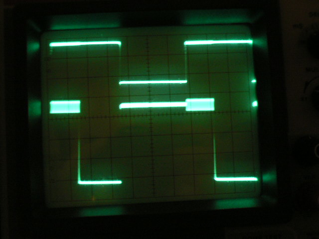
I did some testing and found some of the strange waveforms that Paul and Rob found. I found these at higher frequecies and didn't seem to retrigger the circuit as it was doing to Paul and Rob (they were seeing pulsewidths of ~6ms instead of the 4ms maximum). I added a 6.8uF capacitor from 12v to ground (near the voltage regulator) and that cleared that problem up. Perhaps a larger cap would be even better, but 6.8uF was the largest I had on hand.
No capacitor
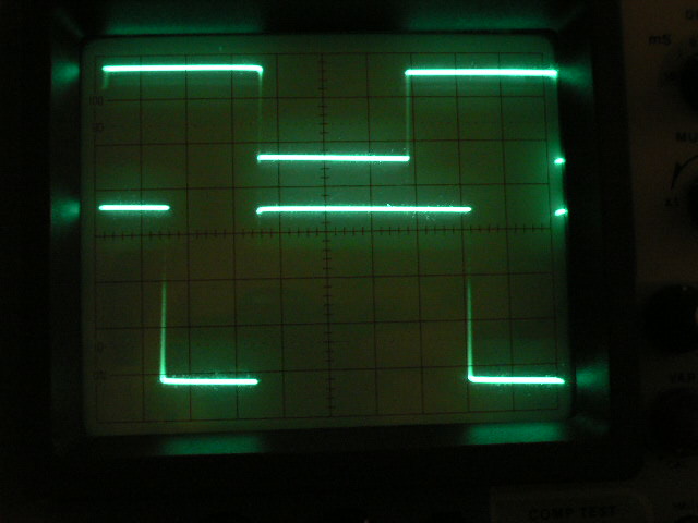
With capacitor
I see a small wiggle in the time where the circuit switches between high and low (both input and output). The wiggle appears to be about 0.05ms. Paul and Rob saw the wiggle on the timing light. However, 0.05ms would be much less than 1* at idle and they were seeing a greater variation. Perhaps the wiggle is in square wave generator.
So far, I don't see much difference in behavior between R2 connected or not. R2 seems to work fine for me with or without the coil connected. I will look into it more, though. I am using a 4A power supply. Perhaps it would be different with a battery.
I also have the old version of the circuit here that I can test as well and compare the results.
So the things we are trying to check, based on what Paul and Rob saw:
- strange waveformon top of the signal (I saw something like this, but not the same type as Paul and Rob. The waveform I had was removed with the capacitor).
- Wiggle in timing
- retarding with RPM. So far, I have not seen this. However, I can't change the frequency very fast with the square wave generator I built. The input and output seemed to be lined up under the frequencies that I have tested so far.
-Different strange waveform with retriggering. This is like the waveform I saw, but only occured at high frequencies for me. No retriggering occured. The addition of the capacitor cleared it up.
I will keep testing and see what I can find. If any of you have ideas you want me to test, let me know.
I got the new scope yesterday. The guy did an excellent job packaging it and even included an english manual. Only took 1 day to get here after he shipped. Nice thing about living in a relatively small country.
Yesterday and today, I had to rig up a square wave generator to simulate the J-109. I don't have a function generator here (that would have been much easier). I had to build something with the limited parts I had. I happened to have a small audio amplifier chip on hand and was able to turn it into a square wave generator.
I did some testing and found some of the strange waveforms that Paul and Rob found. I found these at higher frequecies and didn't seem to retrigger the circuit as it was doing to Paul and Rob (they were seeing pulsewidths of ~6ms instead of the 4ms maximum). I added a 6.8uF capacitor from 12v to ground (near the voltage regulator) and that cleared that problem up. Perhaps a larger cap would be even better, but 6.8uF was the largest I had on hand.
No capacitor
With capacitor
I see a small wiggle in the time where the circuit switches between high and low (both input and output). The wiggle appears to be about 0.05ms. Paul and Rob saw the wiggle on the timing light. However, 0.05ms would be much less than 1* at idle and they were seeing a greater variation. Perhaps the wiggle is in square wave generator.
So far, I don't see much difference in behavior between R2 connected or not. R2 seems to work fine for me with or without the coil connected. I will look into it more, though. I am using a 4A power supply. Perhaps it would be different with a battery.
I also have the old version of the circuit here that I can test as well and compare the results.
So the things we are trying to check, based on what Paul and Rob saw:
- strange waveformon top of the signal (I saw something like this, but not the same type as Paul and Rob. The waveform I had was removed with the capacitor).
- Wiggle in timing
- retarding with RPM. So far, I have not seen this. However, I can't change the frequency very fast with the square wave generator I built. The input and output seemed to be lined up under the frequencies that I have tested so far.
-Different strange waveform with retriggering. This is like the waveform I saw, but only occured at high frequencies for me. No retriggering occured. The addition of the capacitor cleared it up.
I will keep testing and see what I can find. If any of you have ideas you want me to test, let me know.
 05-21-06, 09:10 AM
#927
Rotary Enthusiast
Join Date: Aug 2004
Location: The World
Posts: 1,100
Likes: 0
Received 0 Likes
on
0 Posts
Hey Kent, great to hear you finally have a working scope - looks good to see those traces :-)
It would be interesting to see what happened if you ran it from a battery. It has been a while since looking at the circuit here - it has been working flawlessly for Rob and I ever since we installed it (minus R2)... are you able to replicate the timing retarding with R2 ? We noticed that it would only do the retarding if the coil was plugged in. There's no chane a component is in back to front that may cause this?
Cheers and good luck!
Paul.
05-21-06, 10:30 AM
#928
I haven't been able to duplicate the retarding yet. Either with or without R2, the input and output signals appear to be perfectly in sync with each other. I am not sure what the difference is. I measured current to the coil to see if the power supply was running near its limits. At about 60Hz, the current was around 2A. The current increased to 6.3A as the maximum RPM of the circuit was apprached (equivalent to around 14,000 rpm or so). The power supply is rated at 4.2A, 12v. I didn't check to see if the voltage dropped at the higher frequencies, but I expect it did. The behavior of the circuit remained the same. It appears that the power supply is keeping up with demand. If it wasn't, that is where there may be a difference between a power supply and a battery.
As far as components go, I don't think you have anything backwards. Most don't matter. The only ones that direction matter are: ICs, transistors, voltage regulator, and LEDs. You circuit seems to work except for that strange behavior. I looked at your circuit before, an it looked okay. I will take another look just to be sure. Hopefully, I can replicate the problem so that I can find a solution.
I'll let you guys know.
05-22-06, 02:32 AM
#933
Well, currently this is the only version available, unless you build your own circuit. A couple guys tried the circuit out and had some problems with timing. I am now trying to correct that. Once it is taken care of, these will be shipping out. So far I haven't been able to reproduce the problems that the guys are seeing. This is one disadvantage of testing on the bench compared to having everything in the car. I can't totally reproduce everything that may be going on in the car. I will keep at it. Perhaps a battery could show a bit different results. Unfortunately, I don't have one available (unless I steal one off someone's moped  ).
).
I do remember renns saying that when the ignitor enters current limiting mode, the draw is about 7.5amps. This is only for a short time. I wonder if my power supply can handle that correctly. I was pulling like 6.3amps (average current) and it seemed to work fine. I would like to try with a battery or a desktop PC power supply just to make sure that the power supply that I have isn't changing the behavior of the circuit. I think that it is fine, though. At lower RPM tests, the current is like 2amps and the power supply is rated at 4.2amps.
I will try more tonight. I will check out the coil - terminal to see if the ignitor is reaching the current limiting mode correctly. If not, that may indicate that the power supply is lacking. So far the circuit appears to do everything correctly. The input and output pulses are aligned (seems like no problem with the timing) and the upper and lower pulse limits work correctly. I also have my old TT circuit here, so I can try it out and compare to the new one.
Kent
). I do remember renns saying that when the ignitor enters current limiting mode, the draw is about 7.5amps. This is only for a short time. I wonder if my power supply can handle that correctly. I was pulling like 6.3amps (average current) and it seemed to work fine. I would like to try with a battery or a desktop PC power supply just to make sure that the power supply that I have isn't changing the behavior of the circuit. I think that it is fine, though. At lower RPM tests, the current is like 2amps and the power supply is rated at 4.2amps.
I will try more tonight. I will check out the coil - terminal to see if the ignitor is reaching the current limiting mode correctly. If not, that may indicate that the power supply is lacking. So far the circuit appears to do everything correctly. The input and output pulses are aligned (seems like no problem with the timing) and the upper and lower pulse limits work correctly. I also have my old TT circuit here, so I can try it out and compare to the new one.
Kent
05-22-06, 03:43 PM
#934
I did some more testing tonight. I found that at some frequencies, I was seeing the jitter in the pulse that Paul and Rob were seeing with the timing light. This only occurs with the coil connected and R2 in place. It is very strange because it creates the jitter on the input signal as well. I am not sure how that is connected because R2 only connects to the timing IC to create the upper pulse limit. Now, if I increase R2, the jitter seems to disappear. I will have to experiment with what value works best and to be sure it removes the jitter at all frequencies. With the 39k resistor (one I planned on using), the jitter is there. I tried a 100k, and the jitter is gone. The 100k would put the max pulse limit at 10ms. I am not sure if this will take care of the heating problem or not. Maybe Paul/Rob could try to drop a 100k in for R2 and see how it works. It can't be worse that having no limit like they are running now (in terms of heating). I am using a 6.8uF capacitor as well on the input (12v to ground). It seems to clear up that other waveform stuff.
I check on the ignitor current limiting. At low frequencies, the ignitor enters current limiting after about 5ms of coil charging. Maybe the time would be a bit less if a battery is used. Using 3.9ms for the upper limit, the current limiting mode was just barely reached. This means that the 3.9ms is a pretty good value, but a bit higher may be better. We want the coil to saturate (enter current limiting mode), but we don't want to charge much beyond that as that is the cause of heating. Tomorrow night, I will try some different resistances for R2. It seems that somewhere between 39k and 100k is the magic number. Perhaps a 56k resistor will work best. I guess I will try some different values and see what I can come up with.
I am not sure if the jitter issue is related to the retarding issue that Paul and Rob saw. I assume that it probably is since the problem went away for them when R2 was removed. As far as I can tell, the input and output pulses are always lined up. However, when the jittering occurs, sometimes it looks like the input moves without the output moving or visa versa.
I'll keep you guys informed. I think we are getting close. Maybe Paul and Rob can check out whatever mods we decide on to check for heat and driveability. Once things are good, I will pick up the resistors/capacitors for the fix and start the shipping.
Kent
05-22-06, 05:12 PM
#935

Hey,
Alright i've been following your past few thread and i'm gonna try to do this tonight with a 56k resistor and a cap inbetween groung and 12v ... I just hope that i can find some solder from my buddy, i ran out and all the stores were closed today hopefully i'll give those a try.
Sam
Alright i've been following your past few thread and i'm gonna try to do this tonight with a 56k resistor and a cap inbetween groung and 12v ... I just hope that i can find some solder from my buddy, i ran out and all the stores were closed today hopefully i'll give those a try.
Sam
05-22-06, 10:31 PM
#936
Alright just got back in from outside ... didn't have time to put in the car till like 1/2 and hour ago, so i'm working in the dark. When i went out there .. i hooked up the blue to the red on the 2nd gen coil pack .. the black to ground (the metal backing of the coil pack), the lines to the ingiter (the one closest to the rad), the yelowish line off the igniter to 12v along with the red one off the tt, and obviously alld the spark plug cables ... well the first try i did it, both light went on i knew that it looked wrong but i still decided to give it a whirl ... sounded very different when before, took the timing light out and checked out what was going on trailling was working but no leading ... looked back at the wires and figured out that i actually had hooked up the blue and red wire to 12v and not the yelowish and red one ... so did that and now only the green one was on ... which i believe from reading is what should happen... tried to start the car again, didn't sound as bad but still sounded different and not as smooth. so i took out the timing light to see what was going on this time, trailing was fine but still nothing on the leading .. hmmm i decided to see if there was any spark at all coming out of it so i unpluged the spark line from the spark plug of the front rotor and I just got zapped big time, it was on and off like the ticking that it should be doing sparking the spark plugs, i almost couldn't let go off it and no one was around to really help. But anyhow what do you think i could of done wrong? I should add that I'm using a 56kohm resister as r2 and a 10nf capacitor inbetween 12v and ground ... any help would greatly be appreciated.
05-23-06, 01:33 AM
#937
Hey Sam,
First, let's check the wiring. I imagine that you switched the wiring from the old board to the new. The order of the wires should be:
- black (ground)
- red (12v)
- red (B terminal on J-109 ignitor)
- yellow (C terminal on J-109 ignitor)
- blue (output to 2nd gen coil)
The two red wires don't matter if they are switched because they connect together on the board. It just makes it easier to run power to the TT and from the TT to the ignitor instead of having to run a separate power wire to the ignitor.
If those are correct, the rest of the wiring should look like this:
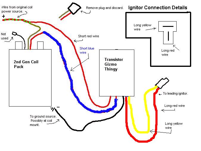
The tan wire on the 2nd gen coil is 12v. The red on the 2nd gen coil connects to the blue on the TT. Also make sure that the spark plug wires are plugged in all the way on the 2nd gen coil. The 1st gen boots do not fit the 2nd gen coil output posts well.
On the capacitor, is it 10nF or 10uF? It won't cause the problem that you are having, but I would go with one closer to 10uF (I am using 6.8uF). When it was running, was the red LED blinking? What about the green one? Sometimes it is had to see the blinking except near idle. If they are both blinking, it means that the signal is getting in and out of the TT. Perhaps the spark plug wires weren't plugged in well. Hopefully nothing got damaged. If just the wires on the coil were reversed, I think that no damaged should have happened. I think 56k for R2 may work well. I will test some different values for R2 tonight to see what works best. Maybe you will need larger than 56k.
Kent
First, let's check the wiring. I imagine that you switched the wiring from the old board to the new. The order of the wires should be:
- black (ground)
- red (12v)
- red (B terminal on J-109 ignitor)
- yellow (C terminal on J-109 ignitor)
- blue (output to 2nd gen coil)
The two red wires don't matter if they are switched because they connect together on the board. It just makes it easier to run power to the TT and from the TT to the ignitor instead of having to run a separate power wire to the ignitor.
If those are correct, the rest of the wiring should look like this:
The tan wire on the 2nd gen coil is 12v. The red on the 2nd gen coil connects to the blue on the TT. Also make sure that the spark plug wires are plugged in all the way on the 2nd gen coil. The 1st gen boots do not fit the 2nd gen coil output posts well.
On the capacitor, is it 10nF or 10uF? It won't cause the problem that you are having, but I would go with one closer to 10uF (I am using 6.8uF). When it was running, was the red LED blinking? What about the green one? Sometimes it is had to see the blinking except near idle. If they are both blinking, it means that the signal is getting in and out of the TT. Perhaps the spark plug wires weren't plugged in well. Hopefully nothing got damaged. If just the wires on the coil were reversed, I think that no damaged should have happened. I think 56k for R2 may work well. I will test some different values for R2 tonight to see what works best. Maybe you will need larger than 56k.
Kent
05-23-06, 03:27 AM
#938
a.k.a TheLatinHeat

Damn I miss this project. hehe but got a new car to try out the new project hopefully soon. Once I figure some little problem I have with the Tach and Oil Pressure guage.
05-23-06, 01:49 PM
#939
Hey kent ... i'm going to be attempting this again in a few minutes ... i will double check all the connections and try to fire her up again. Now that its nice and bright outside it should be alot easier to see things. I'll be back in a few minutes to let you know the results
05-23-06, 02:47 PM
#940
alright so just got back in from out side this is what i got ... i got the setup working as in the lights alternate ... i can see spark via a timing light ... but i cannnot see the marker no matter how advance or retard i do the distributor, i even have the advanced timing light thing and i can take it 60 degrees and i still can' t see the marks on the pulley. idle is pretty rough sounds like it need to be advanced more but i can't take it any more it was advance quite a bit with the stock setup i'm not sure why ... so i can't really take it that much more with the TT. now by reving the engine it sounds like that it actually is advancing be cause it does rev alot faster and sounds alot smoother in the higher revs ... i can't prove that with a timing light though. I'm gonna go back out htere and check resistance see if everything kinda works out. If there's anyway i can advance things even more please let me know ( that is without hacking away at the metal ... also it barely idles right now ... i would have to turn in the idle screw quite considerably to make it idle at around 800 or so, it idles at around 500 right now ... I haven't mounted the whole thing in there so i haven't test driven it with the TT on there but all driveway testing. I need to buy a couple of bolts to mount it on there first. If the timing retards the higher the revs the more the engine stumbles right ?
05-23-06, 02:59 PM
#941
Senior Member
Join Date: Oct 2002
Location: Hampton, VA
Posts: 596
Likes: 0
Received 0 Likes
on
0 Posts
Your pulley may not be on correctly. The 1st gen pulley can go on any way, unlike later pullies that only fit one way. You may look on your pulley for a mark, and try removing (with the 4 10mm fasteners!) the pulley and turning it 90* and trying again.
05-23-06, 03:08 PM
#942
Paul and Rob ran into that. They had to advance the dizzy by 1 tooth, I believe. For some reason, without R2, this does not happen. I tried adding a diode to the ground wire between the TT and the coil pack. I believe it got rid of this retarding, but I will have to check more to be sure. A better option would probably be a ferrite choke on the ground line to keep higher frequency noise from the coils and other systems from interfering with the circuit. Maybe you could try running the ground on the TT directly to battery -. I just can't figure out why some of these things happen with R2 and not without R2. Most of it doesn't seem to have anything to do with R2. It only sets the max pulsewidth.
Perhaps you will need to go higher than 56k for R2. I don't know. Perhaps if we get the inital retarding figured out, everything else will fall into place.
For the TT circuits, I think that all are now reserved. I think that I have eveyone listed that had expressed interest. If others want one, I will add you to a backup list. Some on the list may drop out because they sold their car, decided on another ignition, or whatever. As spots open, they will get filled in order from the people on the backup list. If all sell out, I will do another batch when I return (October) with whatever improvements we find incorporated into the new boards.
Kent
05-23-06, 07:51 PM
#944
Rotary Enthusiast
Join Date: Aug 2004
Location: The World
Posts: 1,100
Likes: 0
Received 0 Likes
on
0 Posts
dj55b, interesting what you are describing. When you run on stock timing, can you see the pulley markers ? If yes, then it sounds like you are experiencing the same problem Rob and I were getting. The timing mark will be almost 180 degrees retarded. I had to lift the dizzy out and rotate it 1 tooth in order to get enough advance for me to line up the mark with the pin. That said, when I pulled on the throttle, the timing retarded (came towards you if standing on left side of car).
If your timing marks are not visible, you should be able to find them - there are usually little grooves about 1cm apart on the pulley, then just use some white-out/paint/nail polish to mark them... then again your pulley could be on bad.
Keep us updated Good to finally have some action on this.
If your timing marks are not visible, you should be able to find them - there are usually little grooves about 1cm apart on the pulley, then just use some white-out/paint/nail polish to mark them... then again your pulley could be on bad.
Keep us updated
Good to finally have some action on this.
05-24-06, 01:40 AM
#945
Tranquil: Don't worry about it. I have you on the list. Anyone that hasn't paid can just wait until the boxes are ready. I am trying to find a way to make it up to the guys that paid already. First priority shipping...partial refund?...some French cheese? I do feel bad that it is taking so long to get these to you guys.
On the testing, I think that perhaps some noise on the ground line is causing problems. I don't see how that relates to R2, though. I have a 4 day weekend (starting tomorrow), so I will have lots of time to test. I am trying various combinations of R2, capacitors, and diodes to correct this. I will see if I can find an electronics shop around here to see if I can get some chokes to maybe cut out any ground noise.
One thing that I have been thinking is perhaps the J-109 is producing a much longer pulse than if it had the coil connected. Paul and Rob were measuring like a 26ms charge time from the J-109 with the TT connected. Based on the numbers that Jeff20B posted before, the coil charge time is like 7.3ms with the coil connected to the J-109 (if I calculated this correctly).
Now, robs_seven on here is running the simple TT circuit and was not experiencing the 2nd gen coil heating problem. We couldn't figure out what was going on. It turns out that his 1st gen leading coil was still connected (sparking into the air). This means that the output from the J-109 must depend on the load it sees. I don't have a 7 here, so I have no way of testing that. Perhaps we can reduce the resistance of the pull-up resistor in the TT circuit. Perhaps that way the pulse from the J-109 will be reduced and we wouldn't even have to worry about R2. The problem is that if we reduced the resistance to the level of the 1st gen coil, the resistor would need to be quite large in size and need to give off a lot of heat. The resistor would probably need to be mounted externally somewhere. Perhaps, though, we can find a value of resistance that works well in between these extremes. Currently, the J-109 sees 1kOhm resistance with the TT connected. Stock, the J-109 sees about 2Ohms. As we decrease resistance, a resistor with a higher power rating is needed. Anyway, if this is true, perhaps it will correct the problem for the people with the old version of the circuit.
Kent
I do feel bad that it is taking so long to get these to you guys.On the testing, I think that perhaps some noise on the ground line is causing problems. I don't see how that relates to R2, though. I have a 4 day weekend (starting tomorrow), so I will have lots of time to test. I am trying various combinations of R2, capacitors, and diodes to correct this. I will see if I can find an electronics shop around here to see if I can get some chokes to maybe cut out any ground noise.
One thing that I have been thinking is perhaps the J-109 is producing a much longer pulse than if it had the coil connected. Paul and Rob were measuring like a 26ms charge time from the J-109 with the TT connected. Based on the numbers that Jeff20B posted before, the coil charge time is like 7.3ms with the coil connected to the J-109 (if I calculated this correctly).
Now, robs_seven on here is running the simple TT circuit and was not experiencing the 2nd gen coil heating problem. We couldn't figure out what was going on. It turns out that his 1st gen leading coil was still connected (sparking into the air). This means that the output from the J-109 must depend on the load it sees. I don't have a 7 here, so I have no way of testing that. Perhaps we can reduce the resistance of the pull-up resistor in the TT circuit. Perhaps that way the pulse from the J-109 will be reduced and we wouldn't even have to worry about R2. The problem is that if we reduced the resistance to the level of the 1st gen coil, the resistor would need to be quite large in size and need to give off a lot of heat. The resistor would probably need to be mounted externally somewhere. Perhaps, though, we can find a value of resistance that works well in between these extremes. Currently, the J-109 sees 1kOhm resistance with the TT connected. Stock, the J-109 sees about 2Ohms. As we decrease resistance, a resistor with a higher power rating is needed. Anyway, if this is true, perhaps it will correct the problem for the people with the old version of the circuit.
Kent
05-24-06, 10:59 PM
#947
I can see the marks fine without the trick on there (they're already painted yellow and white). Now that black line coming out of 2nd gen coilpack is a ground line correct? I wounder if that got connected if it would affect anything. There's one thing that i don't understand though maybe i've missed it or forgot about it, But how does things work if the igniter to the leading is connected to the 2nd gen coil and we're pluggin in the trailings in the place of the leading spots? Also since the timing seems to be out by about 180 degrees, couldn't we install a small coil or capacitor somewhere on the output to correct it ... or atleast by 90 degrees? so that we won't have to move the dizzy by a tooth.
But my answer about retarding was still not answered ... does the engine sound like it stumbles when it retards? Cause if thats the case, then mine was advancing properly cause it did sound smoother in the higer revs. The only stumble that i get is when i press on it at the beginning but thats about it. But thats from my carb and not hte ignition.
But my answer about retarding was still not answered ... does the engine sound like it stumbles when it retards? Cause if thats the case, then mine was advancing properly cause it did sound smoother in the higer revs. The only stumble that i get is when i press on it at the beginning but thats about it. But thats from my carb and not hte ignition.
05-25-06, 03:38 AM
#948
The black line on the 2nd gen coil is not ground. Do not ground it or your 2nd gen ignitor will be toast. That line connects to the C terminal of the ignitor and coil -. It can be used to connect a tach, shift light, etc., but was just there for testing ignition on the 2nd gen cars.
It seems as the problem, with the large retarding is caused by noise on the ground line. I have had some luck correcting this by placing a diode in the ground line for the TT, but I think a ferrite choke or something could work better. Also try connecting the ground for the TT directly to battery - to reduce the interference from the coil pack. It also appears that larger values of R2 create less problems. 100k seems to work pretty well, but I am not sure if it is enough limit to keep coil temperatures down. I still get some jitter in the signal with the 100k. The 100k may reduce the amout that it is retarding as well. You might want to give it a try and let us know.
I will be testing all day trying different combinations of things. My plan is to:
1. reduce ground noise as low as possible
2. make sure the 5v and 12v lines are as noise free as possible.
3. track down the retarding with R2 connected
4. see if I can find the source of jitter
I will let you guys know. I don't have any ferrite chokes or anything similar to try. I will need to see if I can find some around here.
05-25-06, 06:10 AM
#950
Kyle - Yes, I have you on the list if you end up wanting one. I am thinking that we may be able to add resistance across the B and C terminals of the J-109. robs_seven on here is running the simple TT circuit and has not had a problem with the coil getting hot. With his, it turns out that his 1st gen leading coil is still connected (sparking into the air). This may not be the best option, but it does appear that maybe the J-109 pulse is dependent on the resistance it sees. It also appears to be true based on other numbers that I have seen. Paul and Rob found that the J-109 connected produced a pulse of 26ms at idle. However, based on numbers that Jeff20B posted, the stock igniton puts out something like a 7.3ms pulse. If we could find an appropriate sized resistor (power rating and resistance value), perhaps we could connect is across the B and C termals of the J-109. This means that no max pulse limiting circuit would be needed since the pulse from the J-109 would not be too long. The problem is that if we reduce the resistance to equal the stock coil, the resistor would have to be large in terms of power rating (probably 75W-100W). Maybe we can find a resistance that produces an acceptable pulsewidth, but doesn't require such a large power rating.
I don't have my 7 here, so I can test this to see if it is true. It would be cool if someone could use an o-scope and check with the stock ignition and with the TT (could be a TT from the previous GB).
I don't have my 7 here, so I can test this to see if it is true. It would be cool if someone could use an o-scope and check with the stock ignition and with the TT (could be a TT from the previous GB).