Transistor trick for 2GCDFIS.
 04-06-07, 09:21 PM
#1176
Hey guys,
I don't know if there is a clear cut value for the ballast resistance. You will want to increase it instead of decreasing. I believe bad83 (Sam) is running 4 10W, 10Ohm resistors in parallel. He has his externally on the power wire going to the coil. He has ran for about a year like this with no issues as far as I know. I don't think it is an ideal placement as it also influences the voltage at the ignitor (may or may not make a difference). Right now I can't do much testing since my apartment doesn't allow any car work. I will be moving into a house soon, though.
As far as what versions have the problem, it is all of them unfortunately. Although, the original switched unit that Kentetsu had would not have the problem in constant pulsewidth mode (it does throw off the timing a bit, though).
RxDad: I would probably try around 1 ohm to start with. A 10W rating should do. If you can find a higher rated one (like 15 or 25W), that would be even better. Anything above 0.39 Ohms will help. The question is what value is ideal (keep heat down without hurting perfromance).
I am still on a quest to get this issue resolved for you guys. Sorry it is taking so long.
Kent
I don't know if there is a clear cut value for the ballast resistance. You will want to increase it instead of decreasing. I believe bad83 (Sam) is running 4 10W, 10Ohm resistors in parallel. He has his externally on the power wire going to the coil. He has ran for about a year like this with no issues as far as I know. I don't think it is an ideal placement as it also influences the voltage at the ignitor (may or may not make a difference). Right now I can't do much testing since my apartment doesn't allow any car work.
I will be moving into a house soon, though.As far as what versions have the problem, it is all of them unfortunately. Although, the original switched unit that Kentetsu had would not have the problem in constant pulsewidth mode (it does throw off the timing a bit, though).
RxDad: I would probably try around 1 ohm to start with. A 10W rating should do. If you can find a higher rated one (like 15 or 25W), that would be even better. Anything above 0.39 Ohms will help. The question is what value is ideal (keep heat down without hurting perfromance).
I am still on a quest to get this issue resolved for you guys. Sorry it is taking so long.
Kent
 04-06-07, 11:04 PM
#1177
Hey Kent. I am still running the same setup. I have finally got the timing down on my 12A turbo blowthrough. I have the leading at 10 advanced, and the trailing at 0. With 12 pounds of boost, second gear is a nightmare. I went a little rich on the secondary jets, and the plugs still haven't fouled. Actually, they look like they came out of a fuel injected engine. Clean as they can be. I have been "advised" by my fellow turbo guys, that MSD is the only way to go with a blowthrough, but I haven't been convinced just yet!
04-22-07, 06:30 PM
#1178
Senior Member
iTrader: (2)
Join Date: Jul 2003
Location: Newark, DE
Posts: 304
Likes: 0
Received 0 Likes
on
0 Posts
Finally got my first version TT installed this week. Wow.
Still need to get the trailing timing adjusted better.
When I ran it for about 2 hours this afternoon the 2 gen coil was hot.
Next week, I will install the parallel 10ohm 10 watt resistors inline with the switched 12 v.
RXDad
Still need to get the trailing timing adjusted better.
When I ran it for about 2 hours this afternoon the 2 gen coil was hot.
Next week, I will install the parallel 10ohm 10 watt resistors inline with the switched 12 v.
RXDad
10-22-07, 03:36 AM
#1180
Rotary Enthusiast
Join Date: Aug 2004
Location: The World
Posts: 1,100
Likes: 0
Received 0 Likes
on
0 Posts
It works- you just need to change the ballast resistor in the coilpack 
Rob has been running it in his car for over a year now... It did burn out one coilpack, but we had not touched the ballast resistor in that one. The new one has been modded to use a ballast resistor... and is still going strong.
I just though't I'd add there is no doubt that there is a noticable improvement in the feel of the car when you drive it. Much stronger spark at high rpm and stronger over the full range according to the theory, but you feel it in the throttle response and how it drives.
Rob and I did some dyno testing with 2 cars finding a possible 1-4hp improvement on peak power.
Last edited by H4Inf; 10-22-07 at 03:50 AM.
10-22-07, 04:08 AM
#1181
Apathy Isn't Laziness
Join Date: Oct 2007
Location: Edmonton
Posts: 344
Likes: 0
Received 0 Likes
on
0 Posts
Anyone willing to start a new thread and summarize the new modded TT so it can be archived?
How exactly did Rob modify the ballast resistor?
Should I run four 10W, 10Ohm resistors in parallel like bad83 or add the 1 ohm dohikki inside the igniter like MattG?
How exactly did Rob modify the ballast resistor?
Should I run four 10W, 10Ohm resistors in parallel like bad83 or add the 1 ohm dohikki inside the igniter like MattG?
10-22-07, 04:33 AM
#1182
Rotary Enthusiast
Join Date: Aug 2004
Location: The World
Posts: 1,100
Likes: 0
Received 0 Likes
on
0 Posts
Good question... I don't think we ever really got a confirmation on any particular setup of ballast resistor. I think one of the main aims was to dissipate heat, so in that case I'd imagine having 4 would help with that. Also mounting to a heatsink.
Rob mounted his ballast resistor external to the coilpack, on a piece of aluminium to help dissipate heat. I think you can get special adhesives that are designed to provide excellent heat transfer between materials - which would be suitable for this.
Rob mounted his ballast resistor external to the coilpack, on a piece of aluminium to help dissipate heat. I think you can get special adhesives that are designed to provide excellent heat transfer between materials - which would be suitable for this.
10-22-07, 07:39 AM
#1183
I am in the process of testing for the ideal resistance for the ballast resistor. I should have results in a couple weeks. Basically I am going to test a wide range of resistances and measure the resulting coil back temperature for each. Now a higher resistance should mean lower temperature (and therefore longer ignitor life). It would be nice to also have some measure of performance so we can balance performance vs. temperature/life.
The only simple measures of performance that I can think of are:
1. manifold vacuum
2. use oscilloscope to see how far we are going into the current limiting mode
Now, I don't know that manifold vacuum will be very sensitive measure. I imagine if you go way too high on the resistance and really start degrading the spark, then manifold vacuum may suffer.
No. 2 on the list would be the better measure. Ideally, we would want to just barely reach the current limiting mode under all conditions. The current limiting mode is when the coil becomes fully saturated and will not hold any more charge. After this point, the ignitor dumps any extra energy as heat (this is why we have had overheating issues).
As for the location of the ballast, I would prefer it in the stock location (or at least wired between the coil (-) and the ignitor (the resistor cold be inside or outide of the pack). Sam (bad83) wired 4, 10W, 10 Ohm resistors in parallel (giving 2.5 Ohm) on the power line to the coil pack. This seems to work fine, although it will also reduce the voltage to the ignitor a bit. I personally believe that 1 Ohm should do the trick (wired in either location), but I'll see what the testing shows.
I'll start a new thread for the test results and put the link to it on this thread. We can then discuss mounting locations for the ballast. I have tried to find a direct replacement of the stock ballast. I can find them in the correct shape and correct lead location, but the ones that I have found don't seem to have the metal mounting tabs. I'll keep looking, though. If I can find one with the tabs, then we could easily just replace the stock ballast and would make for a cleaner install.
Kent
10-22-07, 06:40 PM
#1185
Apathy Isn't Laziness
Join Date: Oct 2007
Location: Edmonton
Posts: 344
Likes: 0
Received 0 Likes
on
0 Posts
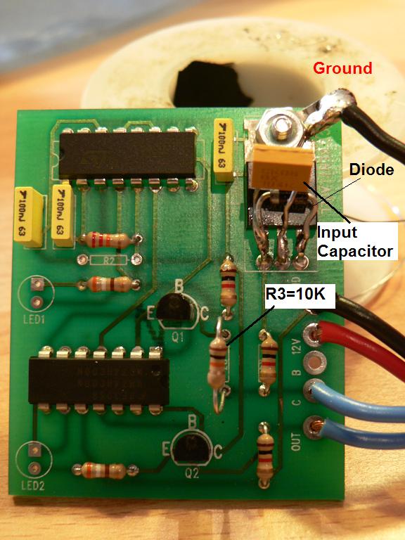
Okay. Here we go. For the mods, I have done the following:
- R3 changed to 10k
- Added ground to tab on voltage regulator
- Added diode (1N4001 type) between input and output of regulator
- Added capacitor between input and ground on regulator (using 0.1uF, may change to 0.33uF)
- Also added diode (1N4001 type) to power line (not shown). The stripe on diode point towards the circuit. This is to prevent circuit damage if power is connected backwards.
For the circuits I send out, I also plan on adding capacitors (bypass caps) between 5v and ground at the ICs. Helps with noise and gives a small storage of power that is used as the circuit switches.
I also did a few measurements for R2. I left the frequency fixed and measured coil charge time and the amount of time in current limiting mode. We want the coil to fully saturate under all conditions, but charging beyond this only adds in heating of the ignitor. In the table listed, I think that the coil charge time increases with current limiting time (5.6ms at 0.6ms current limit time, 5.7ms at 0.7ms current limit time, and so on). It was difficult to measure, so I couldn't get accurate values.
Based on this, it appears that 27k is best under these conditions. As you increase R2, the extra time is spent in current limiting mode (causes coil heating). Perhaps we will just us 27k or 30k. The relation between the input pulse and actual charging of the coil appears to depend on RPM. The coil pack gets pretty warm after a lot of use, but would be better in the car becuase I have no airflow or the metal of the car to conduct the heat away. The temperature appears to be much lower than with the previous circuits. Also, I was testing at low RPM (near idle). At higher RPM, the current limiting time becomes less, so there is less heating of the 2nd gen ignitor.
Can't wait to hear if the timing and all is fixed now. It appears to work correctly on the scope.
Kent
Is this the final setup but with these mods?
- 27k for R2 (may increase to 30k)
- 5.6k fo R3 (may decrease or leave the same)
- Sam is running a 0.33uF cap across the power input
- additional ground at Vreg
- diode inline with 12v line
- diode between input and output of Vreg
- may add 0.1uF caps across the power at each IC (not sure if Sam added these or not)
I am sooo confused, my brain feels like it's been through a blender with how many times R2 and R3 have been changed.
Can someone please post the most recent diagram or pictures of the working TT circuit assuming the use of a 1 OHM ballist resistor mod.
I would like to either buy or make the TT unit as I have just come across a second gen coil. Thanks.
10-22-07, 08:19 PM
#1186
I know it is confusing. This stuff was becuase we were trying to chase down some noise issues, but that wasn't the real problem. When I designed that circuit, it was correct in that it limited the pulsewidth, but the problem is that I forgot the 2nd gen pack fires on the trailing edge of the pulse. This mean that when you cut the pulse short (to try to fix the heat problem), the coil fires at the wrong time.
So, the method to correct the heat issue that we are using now is just to add a ballast resistor. The ballast is not part of this circuit per se. These are a large power resistors that go between the coil (-) terminal and the ignitor. If you open the back of the 2nd gen coil, you'll see the stock ballast (white rectangular thing on the right side). You can replace this with a larger resistance (stock is 0.35 Ohm, you could put something that was arond 1.35 Ohm in its place). The actual value is not that critical. Probably about 1 Ohm or so will do.
If you want to build you own, I have a write-up in the archives. It is essentially the same circuit as the latest design since I ended up bypassing the pulsewidth control on the latest as it didn't work properly. If you want a circuit board to build it on or if you want me to build you one, I can help you out with either once I run a few more tests.
10-24-07, 08:52 PM
#1187

Well I'm back from the dead on this  . Chris (Orion84GSl) came to my house today and in order to help him install the DFIS ... or what ever they call it lol. Anyways. I had both version of Jeff's board, but decided to use the second version because it was professionally done. I have replaced R2 with the 22K ohm resistor, and the car fired right up. This is basically to achive manual mode as described by you Jeff IIRC.
The bad news, lost the light on my timing light, so we had no way of telling what timing we were exactly, and also the car back fired on decel.
Talked to Kent, cleared out a few things ( you tend to forget things after a year lol) and should be doing the modifications again.
. Chris (Orion84GSl) came to my house today and in order to help him install the DFIS ... or what ever they call it lol. Anyways. I had both version of Jeff's board, but decided to use the second version because it was professionally done. I have replaced R2 with the 22K ohm resistor, and the car fired right up. This is basically to achive manual mode as described by you Jeff IIRC. The bad news, lost the light on my timing light, so we had no way of telling what timing we were exactly, and also the car back fired on decel.
Talked to Kent, cleared out a few things ( you tend to forget things after a year lol) and should be doing the modifications again.
10-24-07, 09:09 PM
#1188
My 7 is my girlfriend.
iTrader: (5)
Join Date: Feb 2006
Location: London, Ontario, Canada
Posts: 3,162
Likes: 0
Received 1 Like
on
1 Post
It doesnt seem to be idling very well in its current state, so we may return to stock or just run the DFIS minus the TT the way Ray had his setup. He seemed pretty impressed with his results, so I don't see why I wouldn't be. We shall see
10-25-07, 09:35 AM
#1193
10-25-07, 09:43 AM
#1195
Rotary Enthusiast
Join Date: Aug 2004
Location: The World
Posts: 1,100
Likes: 0
Received 0 Likes
on
0 Posts
10-25-07, 09:50 AM
#1196
My 7 is my girlfriend.
iTrader: (5)
Join Date: Feb 2006
Location: London, Ontario, Canada
Posts: 3,162
Likes: 0
Received 1 Like
on
1 Post
Verify? no, it fired up and ran normally. So I guess we made the mistake of assuming. This car with the stock ignition rarely backfired, except for the odd occasion where I took it through first gear to redline and then came right off the gas. Now it backfires on any decel above of 3-4K. Sure I like the sound, but I've never heard of a backfire being a good thing. I've decided I'm going to stage down to stock, try to see what I like best. I'll pull R2, if I don't like that, I'll pull the TT altogether and just run the 2G coil pack, and so on. Also the poor idle could have alot to do with my dying alternator. Although it idles fine with the stereo cranked and no lights, but the lights make the idle drop by about 2-3 hundred RPM. Also everything ignition related is brand new this year except the coils. Update later.
Last edited by orion84gsl; 10-25-07 at 09:59 AM.
10-25-07, 03:03 PM
#1198
My 7 is my girlfriend.
iTrader: (5)
Join Date: Feb 2006
Location: London, Ontario, Canada
Posts: 3,162
Likes: 0
Received 1 Like
on
1 Post
Well wouldn't you know it, no leading spark. I've changed back to stock, because I don't have time to trouble shoot now, but Sam and I will certainly keep trying this later. If anyone can point us to the culprit of the loss of spark please chime in. Thanks
10-25-07, 03:14 PM
#1199
Check your wiring. Should have:
- 12v to tan wire on pack
- base of pack grounded (bolted to car)
- red wire connected to blue wire on TT
On the TT side:
- short red wire, 12v
- white plug connected to leading J-109 (closest to radiator)
- black, ground
- blue, output to 2nd gen pack
On the TT, does the green LED come on when the key is 'ON'? Does it flash (alog with the red LED) when cranking?
10-25-07, 03:23 PM
#1200
I still do not know why everyone is having so much trouble with this setup. The only thing I can think of is I must have just been lucky. I have my board built like the original curciut, but with the added 2.5 ohms (4, 10 ohm, 10 watt) resistance. The leading did retard a little over 5 degrees, but I set my leading to 10 advance, and the trailing at 20 with no problems for well over a year. I can pull my plugs right now and see they have never burned cleaner. This has served me well up to 10 pounds of boost. I have been playing with 12 pounds here lately, but not quite enough spark for a throttle stomp in first gear. Loads up real bad. I will probably have to go with a MSD (sorry Kent) to clear this stumble up. I don't know what I am doing different to get the results I have, but I can't see this not working great on a N/A setup.