Transistor trick for 2GCDFIS.

 03-26-06, 06:33 PM
#827
Rexy so sexy...
Join Date: May 2004
Location: midwest
Posts: 123
Likes: 0
Received 0 Likes
on
0 Posts
Hey Kent, when you guys have something let me know. My email is in my profile. I just got finished gutting out the dead J109 and installing a HEI module instead. Seems to be working now. It's just weird how the only thing I did different yesterday was connecting that resistor. Maybe part of the wire bridged the two connections instead of just going through the resistor, I don't know. Given the amount of work I just went through today, however, I'll have to wait to see if you guys can come up with anything.
Oh, in case I made it unclear, the stock setup is working now, not the TT setup. I haven't tried it with the HEI so far.
Oh, in case I made it unclear, the stock setup is working now, not the TT setup. I haven't tried it with the HEI so far.
03-30-06, 03:56 PM
#828
Rexy so sexy...
Join Date: May 2004
Location: midwest
Posts: 123
Likes: 0
Received 0 Likes
on
0 Posts
I was talking with my dad last night. He presented the idea that there might be some RF interference from the coil pack. Has anyone tried to shield the circuit box and wires yet?
03-31-06, 12:39 AM
#829
Yes, I do believe it to be RF interference. Probably on the power line. I think we should try to copy the power supply setup from the Megasquirt. I can post a diagram after work. Early in this thread, renns posted scope traces of the 2nd gen coil being triggered by the MS. The signal appears to be clean. The MS power supply is like what I used for the most part with extra capacitance on the input and the output of the 7805 (extra 33 uF on each). This extra capacitance requires a diode that goes between the input and the output on the 7805. This is because when the power is shut off, the 5v side will still be near 5v because of the capacitance, but the input will be at 0. This can cause reverse flow and damage the regulator. It is also a good idea to add a diode on the power input (the MS has this as well). This is to helps momentary drops in voltage (such as cranking) and gives some reverse polaritry protection. The MS also has overvoltage protection and such. We don't really need to worry about this so much.
Another good idea would be to add bypass capacitors (small capacitors that go between 5v and ground near each IC). Maybe I can find some small axial capacitors for this. I could mount them under the ICs.
These few things should take care of it. Once I know for sure that these mods will fix it, I will order the needed parts and start shipping.
Kent
03-31-06, 01:27 AM
#830
Roll to Heaven in a RX-7
Join Date: Feb 2005
Location: New Westminster, B.C - Canada
Posts: 790
Likes: 0
Received 0 Likes
on
0 Posts
after you guys figure out what ever is going on that gets this many posts out. are you gunna make a seprate thread with the conclusion and new directions so that it can be stickyed.
i know you guys are workin hard here doin this but i really in the end do not want to read through all these pages to upgrade
sorry i have been trying to follow but im not smart enough for this stuff
i know you guys are workin hard here doin this but i really in the end do not want to read through all these pages to upgrade
sorry i have been trying to follow but im not smart enough for this stuff
03-31-06, 01:35 AM
#831
MattG FTW!!!!!
iTrader: (2)
Join Date: Feb 2005
Location: South Windsor, CT
Posts: 2,733
Likes: 0
Received 0 Likes
on
0 Posts
What you mean you can follow it??
Its simple you got you 5v Uf if messing with the 75033826 gama's causing there to be a reverse flow action with extra capacitance bypass that to give us some polaritry protection!
Goo what is not to get! lol
Nah JK
Im glad you hero's are on this! This stuff just blows my mind!
Keep us updated on all your hard work, I bet when this gets done its gonna rock!
03-31-06, 01:57 AM
#833
MattG FTW!!!!!
iTrader: (2)
Join Date: Feb 2005
Location: South Windsor, CT
Posts: 2,733
Likes: 0
Received 0 Likes
on
0 Posts
Thats why there heros in my mind!
GSL-SE Addict doesnt need aftermarket parts for his RX, He makes his own and roundhouse kicks RB in the mouth for making an inferior product compared to his!
JK RB rocks!
GSL-SE Addict doesnt need aftermarket parts for his RX, He makes his own and roundhouse kicks RB in the mouth for making an inferior product compared to his!
JK RB rocks!
03-31-06, 02:05 AM
#834
That's funny, Matt. 
rxtory: Sure, we can do that. Probably after more people get some testing in and we know everything is cool. That way we can do a thread with the final design that people can go to directly without sorting through everything else.
After this is done, my next project is going to be a digital Mazda style rotary compression tester. Should be cool. It is something that I have always wanted to try. I will get the design put together and build a prototype when I get back to the states. If all works well, I will have some boards made up and do a GB.
Kent
03-31-06, 02:24 AM
#836
Yeah, that is probably about right. Sooner if I can help it. I just need someone to test it to make sure that this will take care of the noise. I imagine it will, but I would like to know for sure. Maybe dj55b or the Aussies could give it a try. The other possiblity is that I could order the parts that I think will work and send one or two modded circuits out for someone to test. If they work fine, then we know it is clear to ship the rest. If we then needed to make a change, we would have to wait for more parts, though.
I will order the parts from a company here in France to save shipping time and costs.
I will order the parts from a company here in France to save shipping time and costs.
03-31-06, 07:29 AM
#837
Certified Old Fart
Join Date: Oct 2004
Location: Inkerman, On, South of Ottawa, the 2nd coldest Capital in the World
Posts: 490
Likes: 0
Received 0 Likes
on
0 Posts
Woohoo. Kent, your giving me a proud laugh. Me, who knows almost nothing about electronics suggested RF interference some pages back. Boy do I feel smart now!! lol
03-31-06, 09:52 AM
#838
Rexy so sexy...
Join Date: May 2004
Location: midwest
Posts: 123
Likes: 0
Received 0 Likes
on
0 Posts
Kent, I can do testing again. Now that I've switched to HEI, if I blow an ignitor it's dirt cheap to replace. This weekend, I've got access to a timing light. Still no o-scope, but the timing light will tell quite a bit. If you can post up the diagram you mentioned, maybe give me a parts list and what to do with them, I can help. Or, if you want to send me a modded circuit, whatever works. I want to get this thing to work before I buy a 2nd gen!
03-31-06, 10:32 AM
#839
Yeah, that would be cool if you could help. The more help, the better. Here is the diagram from the power section of the MS. If we follow this, we should be good. From nthe diagram, I think we only need:
-C15, C16
-D12, D13
D15 is for over-voltage protection. D14/D16 appear to be for reverse polarity protection. C14 shouldn't be needed. C17 is already on our circuit.
So you should be able to solder C15, C16, and D12 ti the 7805. The caps are polarized, so the negative goes towards ground (center pin). D13 could just be soldered on the power wire somewhere. These mods should smooth out any variations on the power supply.
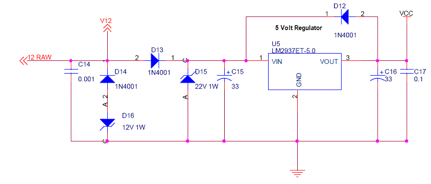
Another good idea is bypass caps. These are usually 0.1 uF caps that go between 5v and ground at each IC (so you would need 2). This helps with noise and gives some energy storage when the IC switches (like using caps for audio amps). Otherwise the voltage drops slightly each time the circuit switches. This small drop can mess up the behavior of the ICs. I imagine that you will add these on the backside of the board. You may what to try to get axial leaded caps (look like resistors) as they may be easier to use. If not, just a cermaic disc cap should do. You can also ask the people at the electronics shop to see what they recommend.
Let me know if you need anything. I will help as much as I can from this end.
Kent
-C15, C16
-D12, D13
D15 is for over-voltage protection. D14/D16 appear to be for reverse polarity protection. C14 shouldn't be needed. C17 is already on our circuit.
So you should be able to solder C15, C16, and D12 ti the 7805. The caps are polarized, so the negative goes towards ground (center pin). D13 could just be soldered on the power wire somewhere. These mods should smooth out any variations on the power supply.
Another good idea is bypass caps. These are usually 0.1 uF caps that go between 5v and ground at each IC (so you would need 2). This helps with noise and gives some energy storage when the IC switches (like using caps for audio amps). Otherwise the voltage drops slightly each time the circuit switches. This small drop can mess up the behavior of the ICs. I imagine that you will add these on the backside of the board. You may what to try to get axial leaded caps (look like resistors) as they may be easier to use. If not, just a cermaic disc cap should do. You can also ask the people at the electronics shop to see what they recommend.
Let me know if you need anything. I will help as much as I can from this end.
Kent
03-31-06, 10:56 AM
#840
Rexy so sexy...
Join Date: May 2004
Location: midwest
Posts: 123
Likes: 0
Received 0 Likes
on
0 Posts
Quick question--what would it take to condition the signal from the dizzy to work with the current circuit design? Since I have a gutted J109 in there now, it was just something I was thinking about. It would be cool to eliminate the ignitor altogether, but I haven't found anything in this thread that would indicate how that could be done.
03-31-06, 11:15 AM
#841
Rexy so sexy...
Join Date: May 2004
Location: midwest
Posts: 123
Likes: 0
Received 0 Likes
on
0 Posts
Ok, I'm still an idiot. I see the caps negative going to the center pin. Where should the positives go exactly? And the diodes? I want to wire this accurately this time. And the bypass caps? I need to know exactly where they will connect to the IC...like I said, I'm still an idiot.
Here's what I get. D12 goes from left pin to right pin on the voltage reg. D13 I have no clue. It looks like C15 and C16 connect to the left and right pins of the voltage reg, positive side on each, and the negative would just connect to ground.
Here's what I get. D12 goes from left pin to right pin on the voltage reg. D13 I have no clue. It looks like C15 and C16 connect to the left and right pins of the voltage reg, positive side on each, and the negative would just connect to ground.
Last edited by devitek; 03-31-06 at 11:22 AM.
03-31-06, 11:17 AM
#842
There is an IC called LM1815. It is a VR conditioning IC. You should be able to connect this IC with some capacitors and resistors to where the J-109 plugs in. The problem is there is no dwell control (pulsewidth change with RPM). You may be able to setup something and run a constant pulsewidth as we did in one of the original TT designs. You would just have to find a value that worked well over the used RPM range. You can check out the Megasquirt section on here or www.msefi.com to read more about it. Guys use this IC with the 2nd gen CAS to do ignition with the MS.
03-31-06, 11:34 AM
#843
Originally Posted by devitek
Ok, I'm still an idiot. I see the caps negative going to the center pin. Where should the positives go exactly? And the diodes? I want to wire this accurately this time. And the bypass caps? I need to know exactly where they will connect to the IC...like I said, I'm still and idiot.
Here's what I get. D12 goes from left pin to right pin on the voltage reg. D13 I have no clue. It looks like C15 and C16 connect to the left and right pins of the voltage reg, positive side on each, and the negative would just connect to ground.
Here's what I get. D12 goes from left pin to right pin on the voltage reg. D13 I have no clue. It looks like C15 and C16 connect to the left and right pins of the voltage reg, positive side on each, and the negative would just connect to ground.
D12 connects between the left and right pins of the 7805. The stripe on the diode faces towards pin 1 (i.e. 12v, input, left pin).
D13 just connects inline to the 12v input to the circuit (12V mark on board). It can be anywhere along the length of the wire. I would put it near the board, so it could go in the box. So:
-cut power wire
-strip ends
-solder stripe end of diode to the part of the wire tha goes to the board
-solder the other end of the diode to the side of the wire that goes to battery/power.
You could throw some heatshrink tubing over it if you want.
For the bypass caps, it would probably be easiest to make a picture. They go between 5v and ground at each IC (usually diagonal from one end of the chip to the other). I will make up a quick pic to make things easier.
Kent
 03-31-06, 12:09 PM
#845
Rexy so sexy...
Join Date: May 2004
Location: midwest
Posts: 123
Likes: 0
Received 0 Likes
on
0 Posts
Sounds good. I'll pick up some more parts tonight on my way home--need more wire and caps. The diodes you suggested to me before, would those work ok? I've still got a ton of those.
And hey, I'm making progress! I had everything but the bypass caps and D13 figured out. There's hope for me yet!
And hey, I'm making progress! I had everything but the bypass caps and D13 figured out. There's hope for me yet!
03-31-06, 12:36 PM
#846
I would probably use the 1N4001 listed in the figure instead. These are designed for power. The ones you have are for a signal. The ones you have may work, but I would get the others instead. These are very common and should be pretty cheap.
Here is a simple diagram of how things connect. Let me know if you have any questions.
Kent

Here is a simple diagram of how things connect. Let me know if you have any questions.
Kent