Transistor trick for 2GCDFIS.
 05-25-06, 02:27 PM
#951
Amish Gangsta
Join Date: Dec 2001
Location: Woodland Hills, CA
Posts: 432
Likes: 0
Received 0 Likes
on
0 Posts
Kent,
Although I have no clue what is going on with the development of the TT Ignition Mod as I am not an electrical engineer, I think I can offer a suggestion or two. If new circuits are coming out every few months we should start referring to them with release numbers, like I suggested many posts ago. This removes the confusion of which circuit the forum is talking about and will also show the relative maturity of such project, what upgrades are effective in each release, etc... I think development continues with version 2.x?
When building the boards perhaps you can incorporate a gang-plug on a small lead so we don't have to butcher up the existing harness that some have spent plenty of time soldering, tie-wrapping and such. The gang-plug could pose a small problem with the enclosure, but with a channel cut out going to the edge of the enclosure base, and an appropriate sized grommet, you probably wouldn't notice the channel and you could just slide the new circuit in the enclosure with the gang-plug hanging out.
I have a web server at home and need to set it up, if you provide me with the details of the circuit versions and all the diagrams, I could host a site dedicated to the Transistor Trick. I expect to have the server set up by the end of this weekend.
PM me if your interested and we'll take this offline for now.
Keep up the good work, and please notify me when a new circuit is available.
 05-25-06, 03:10 PM
#952
Hey Joe,
Thanks for the suggestions. I did send you this version in Feb. Did you ever get it? I sent a few out and then these issues popped up. Most of the circuit is the same as the version I built before going to France. The only difference was the max pulse limiting. On paper and simulations it all worked, so I thought it was cool. However, these issues with large retarding of timing, jittering of the timing, and so on popped up with the additional modification. I am still unsure as the source. I think that after these issues are ironed out, there will probably be no further development of the TT. Performance wise it is good. The only problem is keeping the temps on the 2nd gen coil down.
That's cool on the server. Paul from Australia is putting together a webpage for the TT as well, but there wouldn't be any harm having two sources. Maybe a mirror or something as a backup would be good.
I did try to put a 22k resistor for R2 (tmin=tmax). It didn't seem to retard or jump around. Maybe the guys with the circuit would like to try this. It would effectively be like the original fixed pulse version. For me, the idle was a bit rough and low end wasn't so good with the fixed pulse. High end was good, though. Kentetsu really liked the fixed pulse version. I think his timing is advanced over stock, so that may be the key to get good low end performance. Anyway, the fixed pulse version doesn't heat up the coil pack, so maybe you guys want to try it so that you don't risk your 2nd gen pack.
Kent
05-25-06, 03:21 PM
#954
The one from fall or the new one? The one I sent before I left would be a bit hard to mod to do the fixed pulse, but could be done. The easiest way would be to remove the OR gate IC or cut the output pin. Then make a jumper from the trace that comes into the OR gate from the 4538B IC and connect to where the output was on the OR gate.
On the new, just replace the R2 resistor with a 22k one. Should work. You could then swap out the R2 resistor once these issues are fixed.
On the new, just replace the R2 resistor with a 22k one. Should work. You could then swap out the R2 resistor once these issues are fixed.
05-25-06, 04:10 PM
#956
Yeah, the one from France should only require changing R2 to 22k. There should be 2 22k resistors in the package. Just use those. One of the 22k resistors was marked to go on another place on the board (R3), but that resistor isn't important. So R1=R2=22k, R3 the 30k would be fine. Or you could just find another 22k resistor.
You may want to also add a capacitor at the circuit board between 12v and ground. The data sheet recommends 0.33uF, but bigger should be fine as well. This cleans up the noise on the power to the circuit.
You may want to also add a capacitor at the circuit board between 12v and ground. The data sheet recommends 0.33uF, but bigger should be fine as well. This cleans up the noise on the power to the circuit.
05-25-06, 05:02 PM
#957
I did so testing on the old circuit (one with manual switch between fixed PW and variable). I found that the varible always works correctly. With fixed pulse, it works fine without the coil connected. However, with the coil, the timing changes, the pulse width changes, and there is a bunch of noise. This is probably why the fixed mode never worked right for me. Kentetsu had good luck, though. These were hand built, so it could be variations that way or maybe how his grounds, power, and so on were connected.
I am going to try a few things with this TT as it is a bit simpler than the new one. Perhaps the noise on the ground line is causing timing problems in the 4538B IC. Whatever I find here can transfer over to the new circuit.
I am going to try a few things with this TT as it is a bit simpler than the new one. Perhaps the noise on the ground line is causing timing problems in the 4538B IC. Whatever I find here can transfer over to the new circuit.
05-25-06, 06:25 PM
#958
Alright, I got the old circuit to produce a nice, clean pulse with the coil connected. I wired the multivibrator IC for non-retriggerable operation and added a diode to the ground line. I used a 1N4001, I think, placed inline on the TT ground wire.
I think is was the diode that made the difference. It keeps the noise on the ground from getting back to the TT. The non-retriggerable thing means that the circuit will ignore any input trigger while it is giving an output. This makes sure that noise can't make each pulse longer. I can do this on the new circuit if needed. It may not be pretty as the board traces are setup for retriggerable operation. I would have to cut/bend two pins on that IC and solder jumper wires to two other pins. Wouldn't be too hard to do, though.
The clean operation on the old board didn't even require capacitors on the power lines. It's late here. I will try the diode thing some more on the new TT and try out the non-retriggerable setup in the morning. Hopefully that will clear things up.
05-25-06, 08:59 PM
#960
Rotary Enthusiast
Join Date: Aug 2004
Location: The World
Posts: 1,100
Likes: 0
Received 0 Likes
on
0 Posts
The website that i'm trying to keep track of progress on is here:
http://rx7.pw.cx/transistor_trick/
If there are any updates, please let me know.
Great that there is finally some progress !
!
Cheers,
Paul.
http://rx7.pw.cx/transistor_trick/
If there are any updates, please let me know.
Great that there is finally some progress
!Cheers,
Paul.
05-25-06, 10:52 PM
#961
no clever remarks...
Join Date: Dec 2004
Location: WA State
Posts: 778
Likes: 0
Received 0 Likes
on
0 Posts
Who cares about the board being clean! It will be hidden under a box! Let us know when you figure out the fix and give instructions as to how people with the new circuit boards already can fix their existing boards without having to mail them out to you. Keep up the good work. Thanks!
05-25-06, 11:25 PM
#962
callin' tokyo
Join Date: Dec 2002
Location: Windsor, Ontario
Posts: 1,353
Likes: 0
Received 0 Likes
on
0 Posts
For all those not following too closely, Kent is saying that it's time to chill the Champagne, the party is about to begin.
Oh ya, for all those on this side of the Atlantic, fill the tub with ice and toss in a few cases!
Oh ya, for all those on this side of the Atlantic, fill the tub with ice and toss in a few cases!
 05-26-06, 05:57 PM
#964
Not quite time to chill the Champagne, but I think we are making progress. Sam: Hold off on trying the diode on the ground line. I ran into a problem with that and now I realize what may have happened. With the diode on the line, the ground on the TT is raised about 0.6V above the ground on the car. Now this would normally be cool, but the J-109 pulls the input to the car's ground. This means that from the TT's point of view, the input goes to -0.6V. After a bit of testing, Q1 failed from the reverse bias, I think. Perhaps it was something else entirely. I will check it out to be sure. A better option would be some kind of choke to let the DC through, but cut out the higher frequency noise.
Sam: You could try to add a capacitor between 12v and ground as close to the voltage regulator as possible. The datasheets recommend 0.33uF, so that is what I would try.
I will keep uo the testing. If anyone has ideas, I would be glad to hear them.
Kent
Sam: You could try to add a capacitor between 12v and ground as close to the voltage regulator as possible. The datasheets recommend 0.33uF, so that is what I would try.
I will keep uo the testing. If anyone has ideas, I would be glad to hear them.
Kent
05-26-06, 07:33 PM
#965
alright so i'm holding off the idea of diode for now. Now for choke does it matter what size i use? i think that i have like a 15,33 and a 56 milli henry chokes which one would you advise? As far as the cap i still have the 10nf one inbetween ground and 12 right at where the wires connect on the board. I will try to maybe add a couple more in there just to reduce noise doesn't really hurt anything. The reason that i'm mainly using those 10nf ones is because they're those small caps so its easier to fit in there. I really wish I had an oscilloscope. I might buy one after I buy all the CF stuff from 13beef.
05-27-06, 04:21 AM
#966
Sam: Where are you connecting the ground for the TT? Some of the noise that I am seeing may be because I have to ground everything at the the same point and I am using a power supply instead of a battery. Perhaps if you ran the TT ground directly to the battery - would help things.
I am not sure what would be the best value on the choke. I would try the larger of the two. The frequency that I am seeing is the sparking frequency (20Hz (idle) to 300Hz (high RPM) ). Some of this may just be grounding. I will see if I can find a way to ground things better to see if that will help.
Yeah, it is hard to test much without a scope. Here, I have a scope , but I don't have a car. This makes it difficult to test how everything would work on the car itself. I will keep trying things and see if I can come up with any other ideas.
05-27-06, 05:21 PM
#967
Time to chill the Champagne?
I think we may have it guys.  I discussed the problem with an electronics forum. One suggestion was to reduce R3. This reduces the input impedance and makes it more difficult for noise to switch the circuit. I tried a 10k for R3, but we could maybe go lower. I also ran a 2nd ground wire from the tab on the voltage regulator directly to the coil pack. This reduced the noise on the ground from 0.1V or so down to around 20mV.
I am going to use a 0.33uF capacitor between 12v and ground. I added a diode between the input and output of the voltage regulator (like in the Megasquirt schematic I listed) and put a diode on the power line. These protect the voltage regulator, especially incase the circuit gets wired backwards.
There seems to be no timing change between having R2 or no R2. If there is a difference, it looks to be small. We won't know for sure until someone tries on the car. We may need to experiment to find the best value of R2. I tried 47k. This does get the coil to fully saturate and the current limiting region appears to be small. I think the 47k would work well, or possibly a bit higher (56k?). Tomorrow, I can experiment with different values. I will also put together a pic/list of the changes I did so that Sam or Paul/Rob can try. Things look pretty good on the scope, but it is in the car performance that counts. I really hope that it is now fixed. Once we know it works correctly in the car, I will order the remaining supplies and put together the shipments.
Thanks again for eveyone's help and patience through this.
Kent
I discussed the problem with an electronics forum. One suggestion was to reduce R3. This reduces the input impedance and makes it more difficult for noise to switch the circuit. I tried a 10k for R3, but we could maybe go lower. I also ran a 2nd ground wire from the tab on the voltage regulator directly to the coil pack. This reduced the noise on the ground from 0.1V or so down to around 20mV.I am going to use a 0.33uF capacitor between 12v and ground. I added a diode between the input and output of the voltage regulator (like in the Megasquirt schematic I listed) and put a diode on the power line. These protect the voltage regulator, especially incase the circuit gets wired backwards.
There seems to be no timing change between having R2 or no R2. If there is a difference, it looks to be small. We won't know for sure until someone tries on the car. We may need to experiment to find the best value of R2. I tried 47k. This does get the coil to fully saturate and the current limiting region appears to be small. I think the 47k would work well, or possibly a bit higher (56k?). Tomorrow, I can experiment with different values. I will also put together a pic/list of the changes I did so that Sam or Paul/Rob can try. Things look pretty good on the scope, but it is in the car performance that counts. I really hope that it is now fixed.
Once we know it works correctly in the car, I will order the remaining supplies and put together the shipments.Thanks again for eveyone's help and patience through this.
Kent
 05-28-06, 11:06 AM
#970
sounds good. for sure if you can post a pic of where you want all the other stuff i can prob do that monday morning as i'm not working then. Good to hear we have improvements though. Do you still want me to change to capacitors? I just want to know if i need to go shopping for a few parts or not on monday. I have pretty much all the resistors needed, i have anywhere from like 1ohm up to the 10megaohms. As for diodes i know that i have a few of those those on hand. hopefully you can post up the images and list tonight. THanks
05-28-06, 11:27 AM
#971
Sure thing. I will post up the info in a little while. Basically, just a 10k or less for R3 and perhaps a couple diodes (1N4001 or similar). The capacitor may not be too important. It does help with noise that gets picked up on the power lines. The 56k that you have for R2 should be fine. If timing looks good, it would be interesting to check performance and to see if the coil pack gets hot or not. We can then adjust R2 accordingly.
05-28-06, 02:29 PM
#974
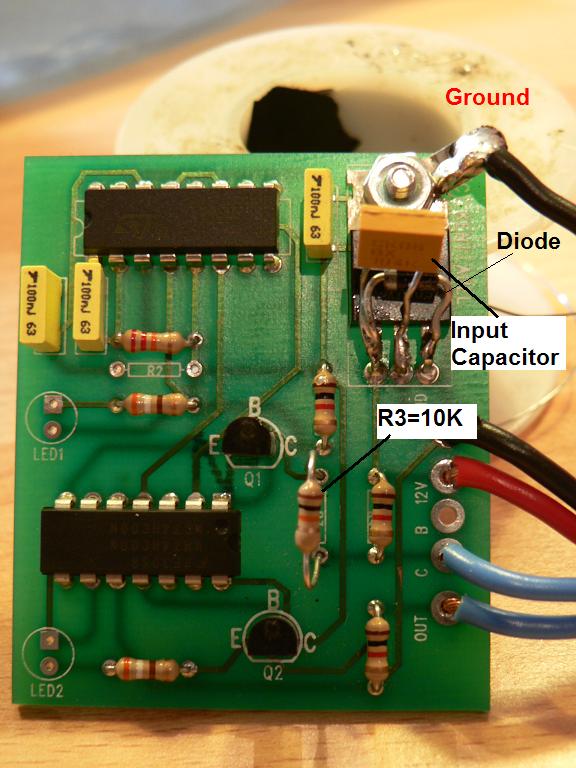
Okay. Here we go. For the mods, I have done the following:
- R3 changed to 10k
- Added ground to tab on voltage regulator
- Added diode (1N4001 type) between input and output of regulator
- Added capacitor between input and ground on regulator (using 0.1uF, may change to 0.33uF)
- Also added diode (1N4001 type) to power line (not shown). The stripe on diode point towards the circuit. This is to prevent circuit damage if power is connected backwards.
For the circuits I send out, I also plan on adding capacitors (bypass caps) between 5v and ground at the ICs. Helps with noise and gives a small storage of power that is used as the circuit switches.
I also did a few measurements for R2. I left the frequency fixed and measured coil charge time and the amount of time in current limiting mode. We want the coil to fully saturate under all conditions, but charging beyond this only adds in heating of the ignitor. In the table listed, I think that the coil charge time increases with current limiting time (5.6ms at 0.6ms current limit time, 5.7ms at 0.7ms current limit time, and so on). It was difficult to measure, so I couldn't get accurate values.
Based on this, it appears that 27k is best under these conditions. As you increase R2, the extra time is spent in current limiting mode (causes coil heating). Perhaps we will just us 27k or 30k. The relation between the input pulse and actual charging of the coil appears to depend on RPM. The coil pack gets pretty warm after a lot of use, but would be better in the car becuase I have no airflow or the metal of the car to conduct the heat away. The temperature appears to be much lower than with the previous circuits. Also, I was testing at low RPM (near idle). At higher RPM, the current limiting time becomes less, so there is less heating of the 2nd gen ignitor.
Can't wait to hear if the timing and all is fixed now. It appears to work correctly on the scope.
Kent
05-28-06, 02:51 PM
#975
when you say you're going to put bypass caps inbetween 5v and ground do you mean across pin 8 and 16 of the chips? Also about the diode on the power line you're refering to the 12v input line to the board correct? If thats the case i'll just take out the wire, solder the diode in and the wire to it and then use heat shrinking tube to cover the whole thing. I'm going to try to find a tab for the voltage regulator on this thing. I will probably just run a wire from there to the ground line, which will all be going to the battery's connection and not to bare metal on the body.
Does anyone know what size bolt are those on the strut tower? I want to bolt the igniter there but I don't have the bolts.
Does anyone know what size bolt are those on the strut tower? I want to bolt the igniter there but I don't have the bolts.