What did you do to your FB today?
 01-14-15, 12:47 AM
#5526
Well, if a picture says 1,000 words - how many words does a moving picture with sound say?..
Compression is bad to say the least. Can some of you more experienced rotary guys tell me what the pulses mean again? I know there's a science to knowing when a side seal is bad versus an apex seal, I'm just not versed in that rotary magic. I'd love to learn though!
Needless to say the engine is getting pulled soon (potentially tomorrow) and torn down to see what the damage is internally. I was kinda hoping I wouldn't have to tear this one down and that I could just figure out the no starting issue, but that just wasn't the case this time.
 01-14-15, 01:00 AM
#5527
Alright fellas, that initial video is going to get renamed "testing a rotary with the Schrader valve installed in the compression tester".
I'm gonna go bury my head in the pillow for a while and pretend like I didn't test the car with the valve still in place and get a faulty reading...maybe some sleep will help cure some of the stupidity.
I'm gonna go bury my head in the pillow for a while and pretend like I didn't test the car with the valve still in place and get a faulty reading...maybe some sleep will help cure some of the stupidity.
01-14-15, 09:57 AM
#5528
I think you're overthinking the dizzy install a bit - natural to do when fighting a problem.
The WHOLE GOAL is to end up with the reluctor tip lined up with the the leading pickup coil core. This may not put the mounting stud in the middle of the adjustment slot - - that's why there's a slot instead of a hole. Sometimes you go to stab the dizzy and the gear teeth just happen to be directly on top of each other, forcing you to rotate the dizzy a bit to get things to drop in. No worries, so long as the stud is somewhere in the slot & not hard up against one end when you have the reluctor and coil lined up.
In your photos above, the lead coil is the one to the left side of the pic (easy way to tell: the coil attached to the vacuum advance diaphragm with the adjustment screws is always trailing). Neither pic shows correct orientation when installed @ TDC. The first pic has the TRAILING coil aligned (meaning your timing is 20* off in the 'retarded' direction) and the second pic is about 30* off the other way; probably a full tooth off.
Having the reluctor tip visually lined up with the lead coil core @ TDC will put you within a couple degrees of correct timing - good enough to fire up if all else is OK. Then you can get the timing exact once the engine is running.
Line up the index marks
Stab the dizzy in
Tweak the rotation to line up the reluctor tip with the lead coil core
Snug the nut and move on to other issues.
As to the dizzy rotor "tree;" yours is kind of an odd-looking beast compared to all the ones I've had over the years, & if it truly is fitting on the shaft with that much play I would replace it if I were you - - it really should fit on the shaft in one definite position with no rotational play.
HOWEVER, keep in mind that the dizzy shaft is not solid from one end to the other! It is a two-piece shaft with the top and bottom halves connected by the spring-loaded centrifugal advance mechanism.
The centrifugal advance mechanism in the dizzy, which lives under the pickup coils, will allow the top part of the shaft to rotate something like 1/8th turn in one direction under moderate spring tension. This means you can turn the rotor (your 'tree') in the forward direction against spring resistance when the dizzy is installed, & it should then snap back when released.
I'll snap you a pic of where my dizzy is set tonight when I get home. It'll look odd compared to yours being an SA dizzy, but the timing alignment works the same. I just checked my timing recently so I know its right-on.
01-14-15, 10:20 AM
#5529
Moderator
iTrader: (3)
Join Date: Mar 2001
Location: https://www2.mazda.com/en/100th/
Posts: 31,121
Received 2,786 Likes
on
1,972 Posts
Alright fellas, that initial video is going to get renamed "testing a rotary with the Schrader valve installed in the compression tester".
I'm gonna go bury my head in the pillow for a while and pretend like I didn't test the car with the valve still in place and get a faulty reading...maybe some sleep will help cure some of the stupidity.
I'm gonna go bury my head in the pillow for a while and pretend like I didn't test the car with the valve still in place and get a faulty reading...maybe some sleep will help cure some of the stupidity.
based on that. i would unplug the fuel pump (or relay) whichever is easier. then hook up your timing light, jump the start wire (there is a connector in the engine bay around the steering box, unplug, and you can bypass the ignition switch, and crank the engine from the engine bay.
point the timing light at the pulley, and crank the engine. move distributor until the timing light says the timing is correct. <-- eliminates thinking.
01-14-15, 11:16 AM
#5530
I think you're overthinking the dizzy install a bit - natural to do when fighting a problem.
The WHOLE GOAL is to end up with the reluctor tip lined up with the the leading pickup coil core. This may not put the mounting stud in the middle of the adjustment slot - - that's why there's a slot instead of a hole. Sometimes you go to stab the dizzy and the gear teeth just happen to be directly on top of each other, forcing you to rotate the dizzy a bit to get things to drop in. No worries, so long as the stud is somewhere in the slot & not hard up against one end when you have the reluctor and coil lined up.
In your photos above, the lead coil is the one to the left side of the pic (easy way to tell: the coil attached to the vacuum advance diaphragm with the adjustment screws is always trailing). Neither pic shows correct orientation when installed @ TDC. The first pic has the TRAILING coil aligned (meaning your timing is 20* off in the 'retarded' direction) and the second pic is about 30* off the other way; probably a full tooth off.
Having the reluctor tip visually lined up with the lead coil core @ TDC will put you within a couple degrees of correct timing - good enough to fire up if all else is OK. Then you can get the timing exact once the engine is running.
Line up the index marks
Stab the dizzy in
Tweak the rotation to line up the reluctor tip with the lead coil core
Snug the nut and move on to other issues.
As to the dizzy rotor "tree;" yours is kind of an odd-looking beast compared to all the ones I've had over the years, & if it truly is fitting on the shaft with that much play I would replace it if I were you - - it really should fit on the shaft in one definite position with no rotational play.
HOWEVER, keep in mind that the dizzy shaft is not solid from one end to the other! It is a two-piece shaft with the top and bottom halves connected by the spring-loaded centrifugal advance mechanism.
The centrifugal advance mechanism in the dizzy, which lives under the pickup coils, will allow the top part of the shaft to rotate something like 1/8th turn in one direction under moderate spring tension. This means you can turn the rotor (your 'tree') in the forward direction against spring resistance when the dizzy is installed, & it should then snap back when released.
I'll snap you a pic of where my dizzy is set tonight when I get home. It'll look odd compared to yours being an SA dizzy, but the timing alignment works the same. I just checked my timing recently so I know its right-on.
The WHOLE GOAL is to end up with the reluctor tip lined up with the the leading pickup coil core. This may not put the mounting stud in the middle of the adjustment slot - - that's why there's a slot instead of a hole. Sometimes you go to stab the dizzy and the gear teeth just happen to be directly on top of each other, forcing you to rotate the dizzy a bit to get things to drop in. No worries, so long as the stud is somewhere in the slot & not hard up against one end when you have the reluctor and coil lined up.
In your photos above, the lead coil is the one to the left side of the pic (easy way to tell: the coil attached to the vacuum advance diaphragm with the adjustment screws is always trailing). Neither pic shows correct orientation when installed @ TDC. The first pic has the TRAILING coil aligned (meaning your timing is 20* off in the 'retarded' direction) and the second pic is about 30* off the other way; probably a full tooth off.
Having the reluctor tip visually lined up with the lead coil core @ TDC will put you within a couple degrees of correct timing - good enough to fire up if all else is OK. Then you can get the timing exact once the engine is running.
Line up the index marks
Stab the dizzy in
Tweak the rotation to line up the reluctor tip with the lead coil core
Snug the nut and move on to other issues.
As to the dizzy rotor "tree;" yours is kind of an odd-looking beast compared to all the ones I've had over the years, & if it truly is fitting on the shaft with that much play I would replace it if I were you - - it really should fit on the shaft in one definite position with no rotational play.
HOWEVER, keep in mind that the dizzy shaft is not solid from one end to the other! It is a two-piece shaft with the top and bottom halves connected by the spring-loaded centrifugal advance mechanism.
The centrifugal advance mechanism in the dizzy, which lives under the pickup coils, will allow the top part of the shaft to rotate something like 1/8th turn in one direction under moderate spring tension. This means you can turn the rotor (your 'tree') in the forward direction against spring resistance when the dizzy is installed, & it should then snap back when released.
I'll snap you a pic of where my dizzy is set tonight when I get home. It'll look odd compared to yours being an SA dizzy, but the timing alignment works the same. I just checked my timing recently so I know its right-on.
I'll be shopping for a new distributor tree - the technical name is a rotor by the way, just looked that up (I'm trying to learn all the correct names for the parts, thanks for the help with that!). I'm going to try and see where I can get a cap and rotor, I'll probably go the RockAuto route. Their parts are always correct, so long as you don't order the wrong part, they have the largest 1st Gen inventory as far as I know and their prices are better than anywhere else that I've found.
The spring resistance in the distributor is pretty cool to feel, I didn't know it could move so much under vacuum. I know what you mean by the movement in the shaft of the distributor - I could feel that as well. The deflection in the rotor displacement that I feel to be about 15 degrees or more is based on the poor rotor design. That movement happens while holding the reluctor still - that's how terrible it is!
I'm probably going to order this rotor from RA today so it'll get here late this week or early next week, should help some of the issue I hope.
BOSCH 04133 Distributor Rotor - $8.45
I'd really appreciate a picture of a distributor at TDC, thanks for the offer! That should help me visualize what I should be looking at. I've never dealt with a timing issue this severe before (well, I never had a timing issue with any of the 4 other 7's I've owned so far).
i see even bounces, although either the engine is cranking really slowly or its dead. the pulses seem low too, but i'd condemn the compression tester before the engine. actually if the engine is badly flooded, it will have low compression, so you need to get the thing running.
based on that. i would unplug the fuel pump (or relay) whichever is easier. then hook up your timing light, jump the start wire (there is a connector in the engine bay around the steering box, unplug, and you can bypass the ignition switch, and crank the engine from the engine bay.
point the timing light at the pulley, and crank the engine. move distributor until the timing light says the timing is correct. <-- eliminates thinking.
I'll unplug the fuel pump, I have the plug easily accessible since the bin hasn't been in its place behind the driver since I bought the car. I'll search for that connector that lets me crank the engine bypassing the ignition, I didn't know there was one! I had planned on going out there with jumper cables and clamping the positive one to the starter solenoid (ignition + and the post the fuseable link connects to - allowing it to extend outwards and spin at the same time), the negative to the block and the other side straight to the battery so it's getting all the juice possible. But jumping a single wire will be much easier!
I moved down here for school so I don't have a timing light either, going back to the store again today! It's fine with me though, my tool collection has grown larger than I have space for - which is a very good thing. I'll remember to pick one up later today.
On a related note, I did test the engine incorrectly didn't I? That Schrader valve at the bottom of the compression tester needs to be removed to get an accurate reading on a rotary right? I left it on for the video because I didn't know any better. I'm going to retest it today with that valve removed to see the difference - I'll record it again as well so it's well documented and that I can re-watch as often as I want it and analyze it.
01-14-15, 11:24 AM
#5532
Moderator
iTrader: (3)
Join Date: Mar 2001
Location: https://www2.mazda.com/en/100th/
Posts: 31,121
Received 2,786 Likes
on
1,972 Posts
On a related note, I did test the engine incorrectly didn't I? That Schrader valve at the bottom of the compression tester needs to be removed to get an accurate reading on a rotary right? I left it on for the video because I didn't know any better. I'm going to retest it today with that valve removed to see the difference - I'll record it again as well so it's well documented and that I can re-watch as often as I want it and analyze it.
 01-14-15, 11:39 AM
#5533
Ok cool, thanks for the encouragement!  I'll redo the test without the valve, check the timing with a new light, make sure the engine isn't flooded while doing either of these tests (unplugged fuel pump, open spark plug holes and open throttle to clear everything out) and do some work on sealing the garage door while I'm out there too.
It's a heat wave here today - it's above 20 degrees!
I'll redo the test without the valve, check the timing with a new light, make sure the engine isn't flooded while doing either of these tests (unplugged fuel pump, open spark plug holes and open throttle to clear everything out) and do some work on sealing the garage door while I'm out there too.It's a heat wave here today - it's above 20 degrees!
01-14-15, 12:31 PM
#5534
DreamIn,
You need a good battery that will crank that engine...cranking speeds that low will give you really poor compression readings. I've done this with some spare engines with a crappy battery with poor connectivity to the starter and had similar readings. Once you get cranking speeds of 200rpm or better, you'll see more realistic compression readings.
Regarding the schraeder valve, if you leave it in AND you don't depress the button on the tester, you should get a reading of the highest compression of a single rotor face (you won't know which, of course). When I did this on a couple of my good 12As, I got anywhere from 85 to 105 PSI compression using a piston compression tester.
The second test I do gives me the relative compression of each face to each other. I either remove the schraeder valve or keep the button depressed and then crank. The best way is to remove the valve all together.
This will cause the needle to bounce. You are looking for 3 even bounces. Even if the numbers are low, that doesn't matter...you're looking to be sure you're making even compression on all faces of the rotor. When I did this on good engines, my tester read about 35PSI.
If you get 1 bounce and two less than optimal bounces, you have a bad apex seal (2 faces of the rotor aren't making compression). If you get 2 good bounces and one less than optimal bounce, you likely have a bad/stuck side seal.
But the bottom line is you need to make sure you're battery is capable of cranking that engine over at 200+ rpm. The Mazda manual (as well as their factory compression testers) show a graph that maps compression w/ cranking speed. The lower the cranking speed, the lower the compression numbers.
fm
01-14-15, 11:44 PM
#5536
DreamIn,
You need a good battery that will crank that engine...cranking speeds that low will give you really poor compression readings. I've done this with some spare engines with a crappy battery with poor connectivity to the starter and had similar readings. Once you get cranking speeds of 200rpm or better, you'll see more realistic compression readings.
Regarding the schraeder valve, if you leave it in AND you don't depress the button on the tester, you should get a reading of the highest compression of a single rotor face (you won't know which, of course). When I did this on a couple of my good 12As, I got anywhere from 85 to 105 PSI compression using a piston compression tester.
The second test I do gives me the relative compression of each face to each other. I either remove the schraeder valve or keep the button depressed and then crank. The best way is to remove the valve all together.
This will cause the needle to bounce. You are looking for 3 even bounces. Even if the numbers are low, that doesn't matter...you're looking to be sure you're making even compression on all faces of the rotor. When I did this on good engines, my tester read about 35PSI.
If you get 1 bounce and two less than optimal bounces, you have a bad apex seal (2 faces of the rotor aren't making compression). If you get 2 good bounces and one less than optimal bounce, you likely have a bad/stuck side seal.
But the bottom line is you need to make sure you're battery is capable of cranking that engine over at 200+ rpm. The Mazda manual (as well as their factory compression testers) show a graph that maps compression w/ cranking speed. The lower the cranking speed, the lower the compression numbers.
fm
You need a good battery that will crank that engine...cranking speeds that low will give you really poor compression readings. I've done this with some spare engines with a crappy battery with poor connectivity to the starter and had similar readings. Once you get cranking speeds of 200rpm or better, you'll see more realistic compression readings.
Regarding the schraeder valve, if you leave it in AND you don't depress the button on the tester, you should get a reading of the highest compression of a single rotor face (you won't know which, of course). When I did this on a couple of my good 12As, I got anywhere from 85 to 105 PSI compression using a piston compression tester.
The second test I do gives me the relative compression of each face to each other. I either remove the schraeder valve or keep the button depressed and then crank. The best way is to remove the valve all together.
This will cause the needle to bounce. You are looking for 3 even bounces. Even if the numbers are low, that doesn't matter...you're looking to be sure you're making even compression on all faces of the rotor. When I did this on good engines, my tester read about 35PSI.
If you get 1 bounce and two less than optimal bounces, you have a bad apex seal (2 faces of the rotor aren't making compression). If you get 2 good bounces and one less than optimal bounce, you likely have a bad/stuck side seal.
But the bottom line is you need to make sure you're battery is capable of cranking that engine over at 200+ rpm. The Mazda manual (as well as their factory compression testers) show a graph that maps compression w/ cranking speed. The lower the cranking speed, the lower the compression numbers.
fm
I know that this car needs a new battery. I also want to try and get another automatic starter to see if that would help as well - because this one seems to be barely working.
You can see the readings that I got with the Schrader valve in place and I'm going to post another video without it installed in the compression tester. I'm thinking that both rotors have one dead apex seal based on one good bounce, two bad bounces on both rotors.
I don't think it would really matter how fast it's cranking if both rotors have a dead apex seal. I didn't even bother to put the distributor back in because I'm going to have to pull this engine now.
Thanks for the help!
DIR
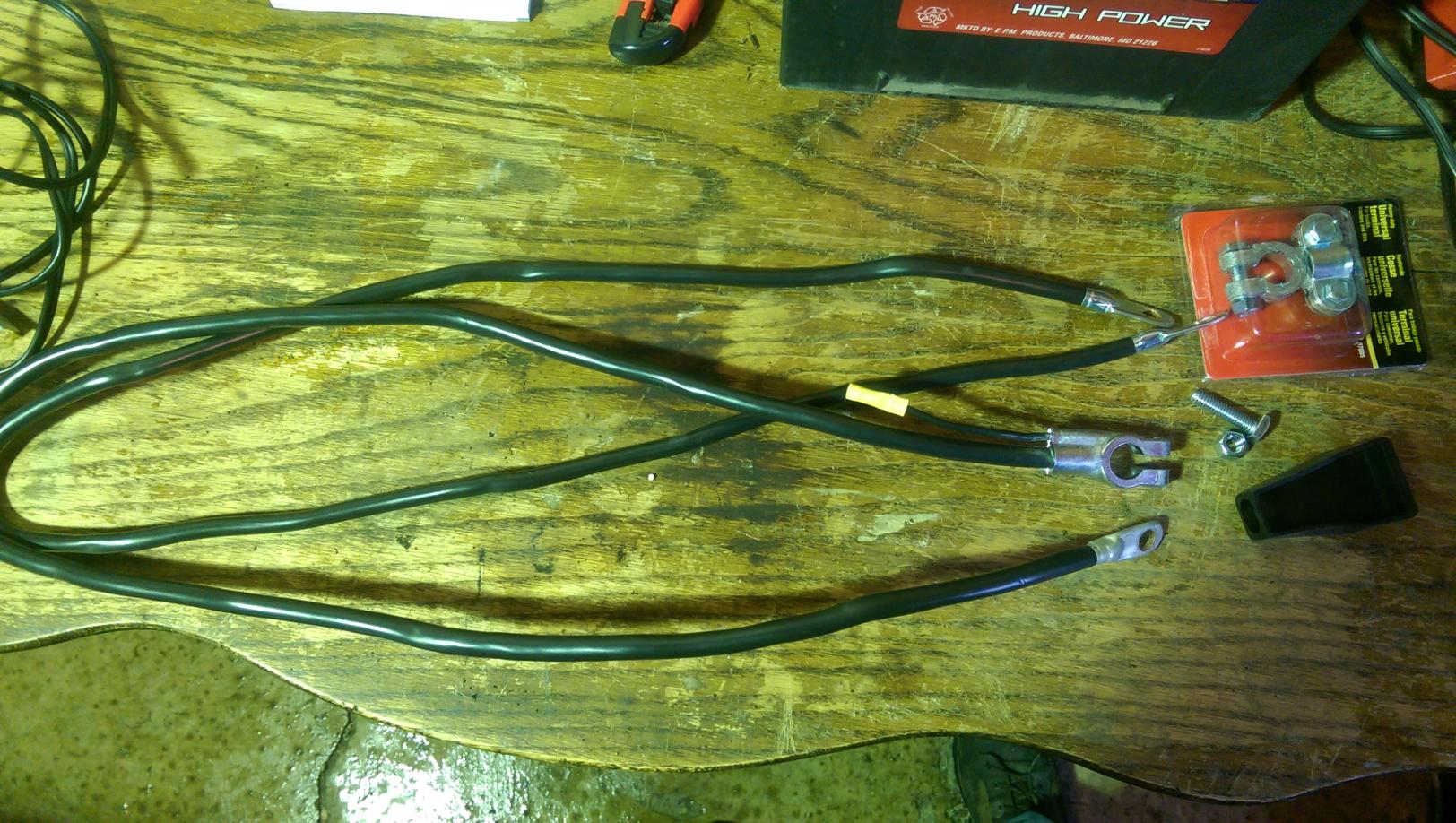
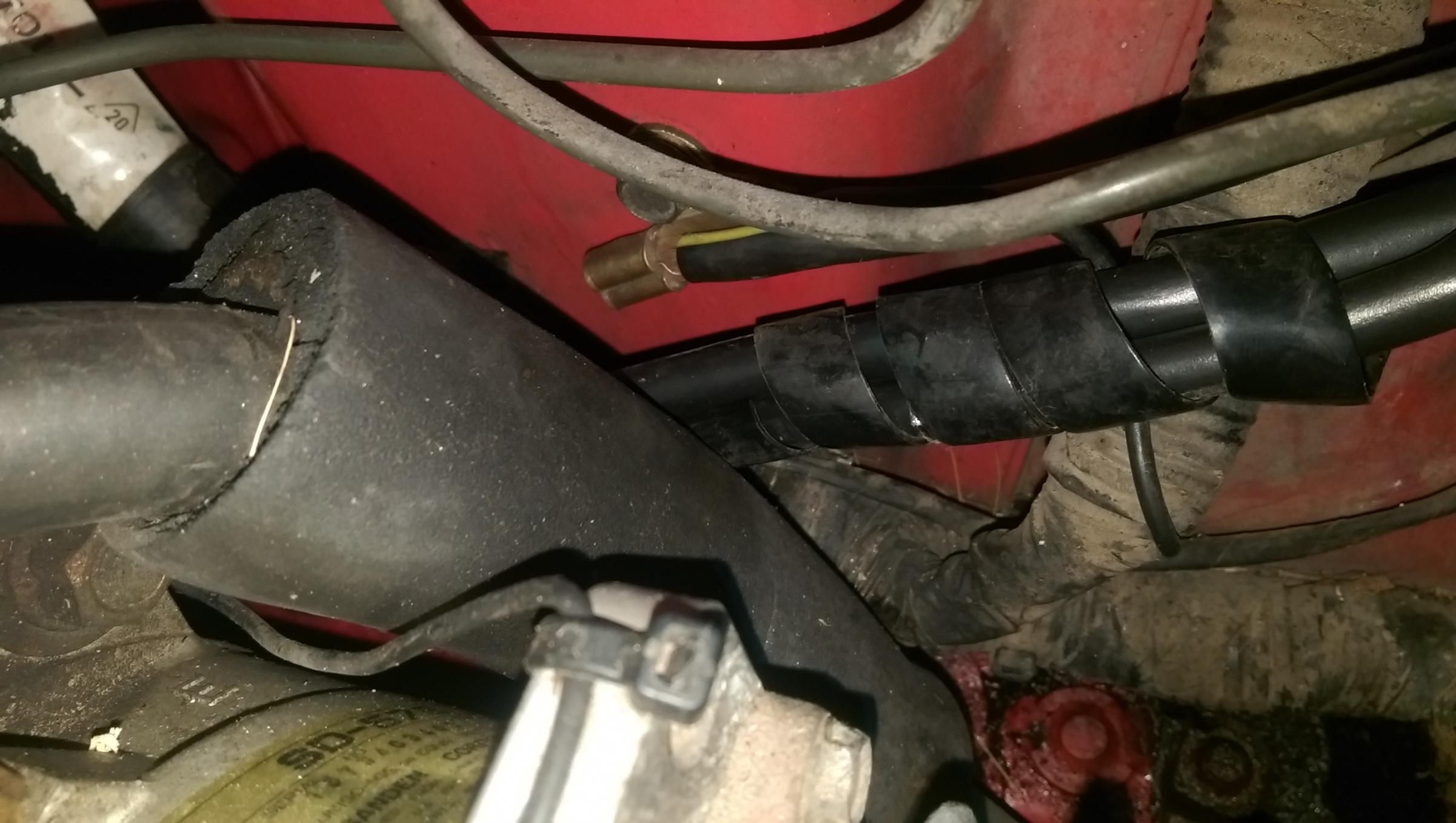
In order to try and solve part of the slow cranking issue I decided to tackle the battery cables today and replace them with new ones.
This is a shot of the old cables at the battery end where the clamps should be.
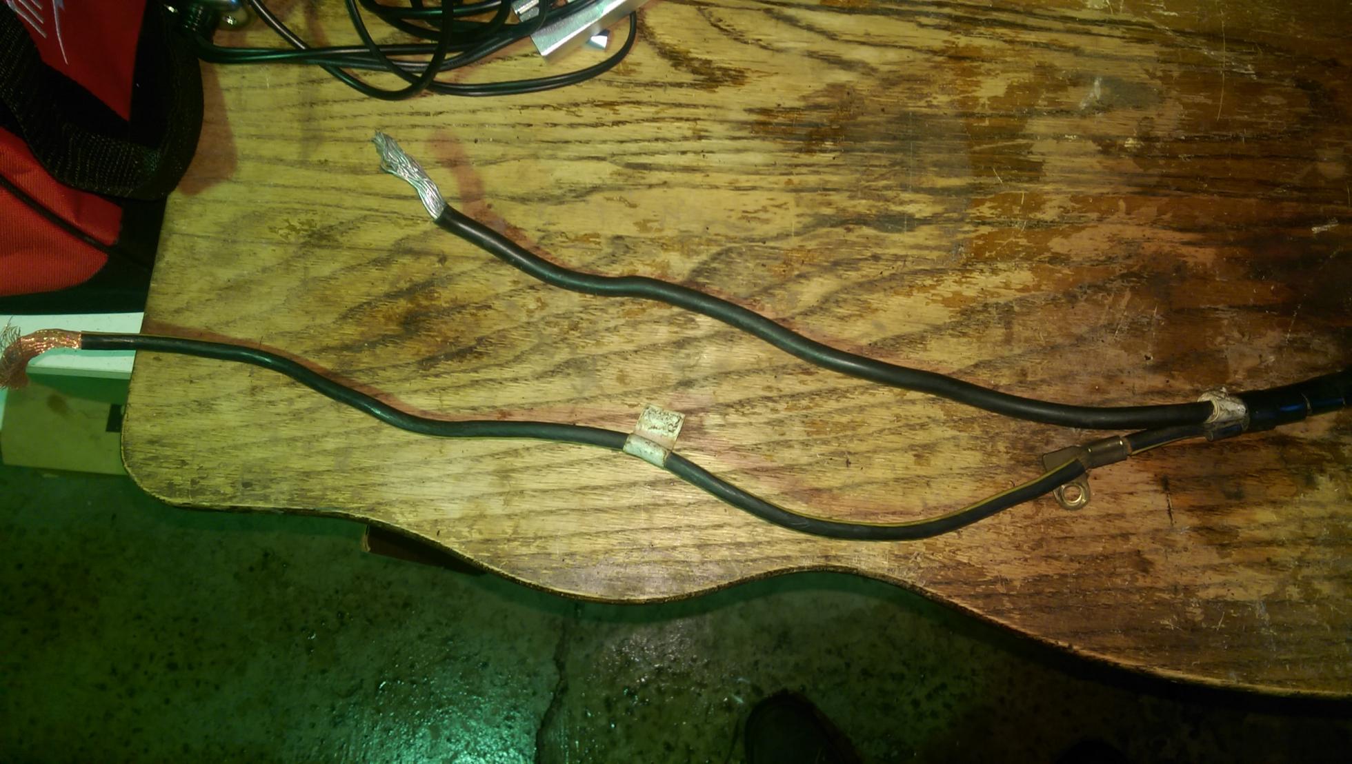
Here's the end where the ground strap bolts to the bellhousing and the positive cable goes to the starter.
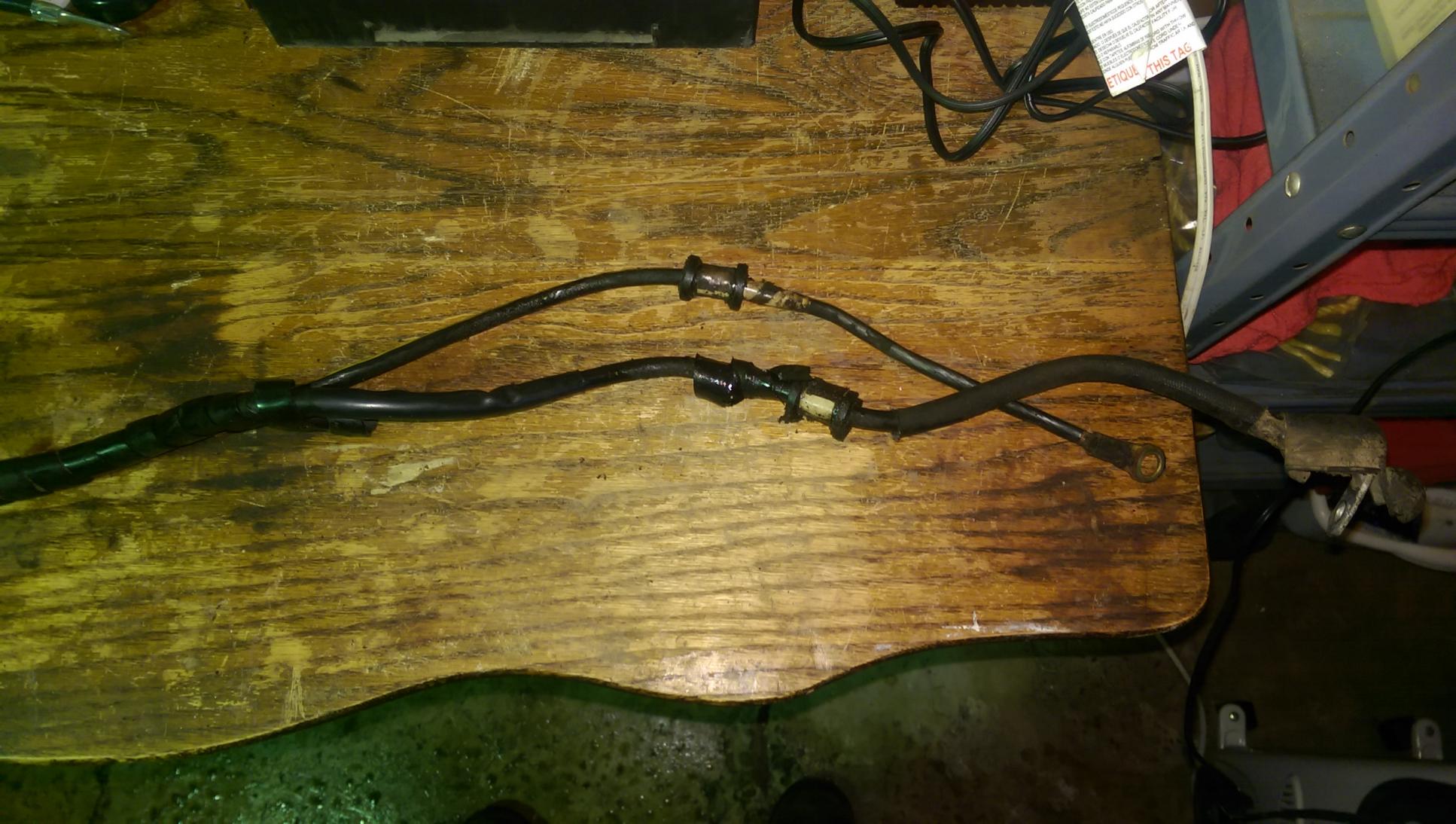
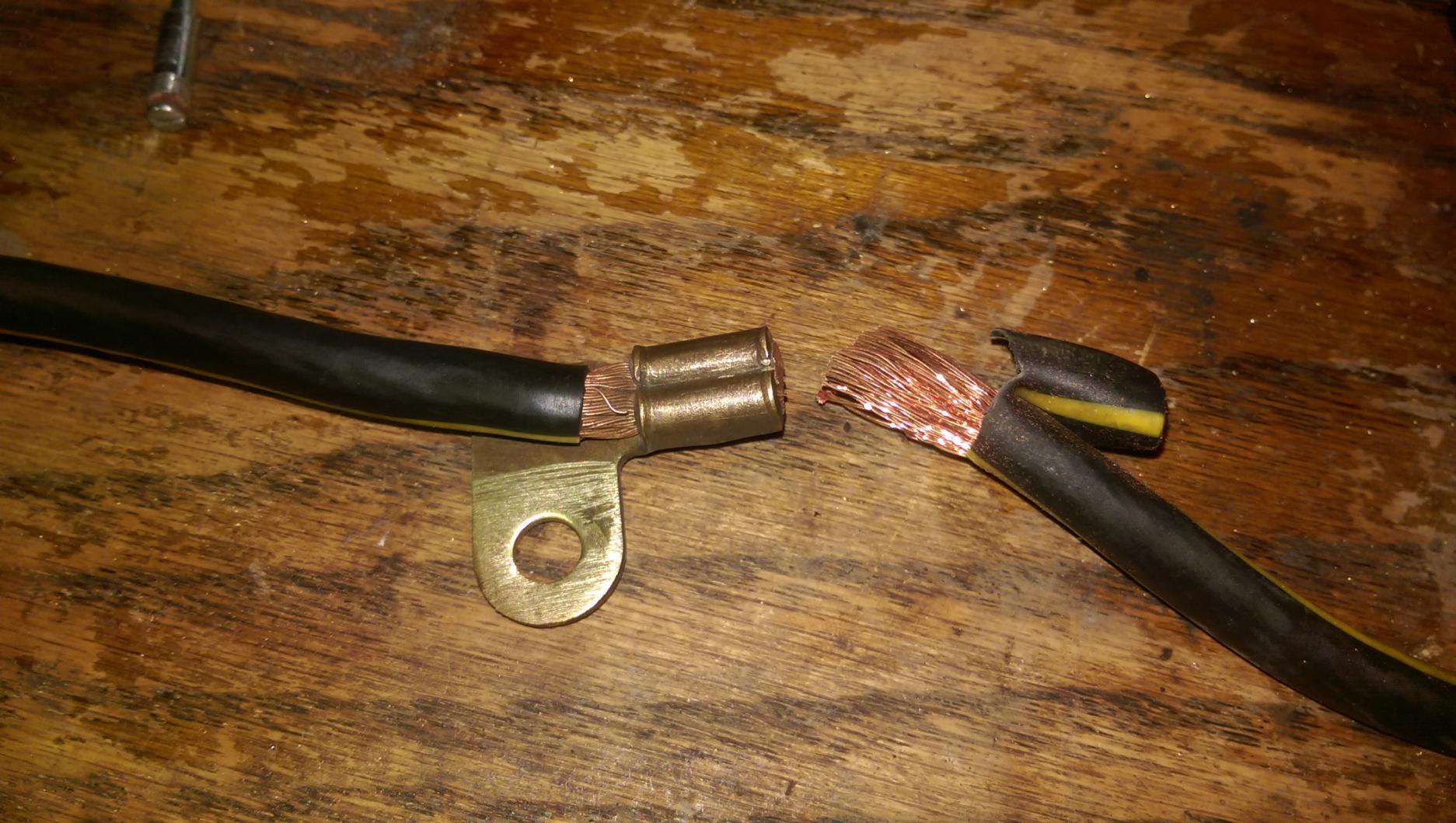
I cut the original ground strap right after the strut chassis ground in order to reuse the chassis ground portion. This eliminated the need to splice into the new cable to make for a new chassis ground.
Here's the new parts I bought from AutoZone for the new wiring setup:
$4.49 - Heavy-duty battery terminal
$9.49 - 4 gauge 49"battery cable with ring terminals at both ends
$14.29 - 2 gauge 48" battery cable with ring terminal at one end and top-post battery clamp
$28.27 - total for all new parts
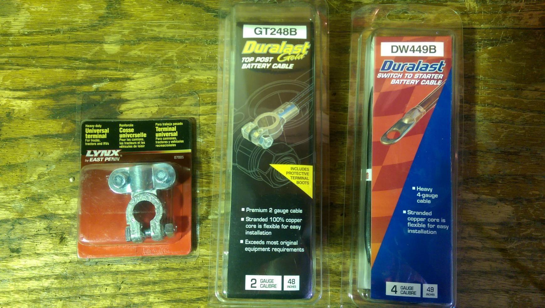
New parts laid out on the table for comparison.
Old, barely-working battery terminals - the ground barely worked at all due to poor contact at the negative terminal.
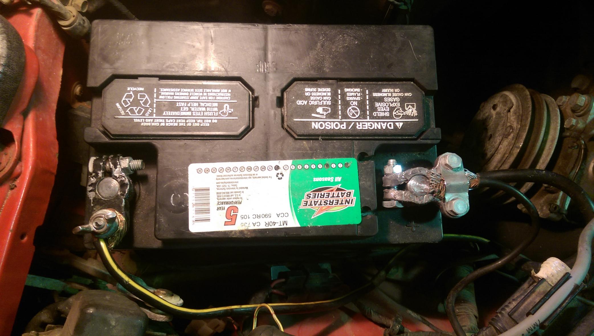
New, much improved terminals! I need to wrap the positive one with some red electrical tape so no one accidentally crosses the wires.
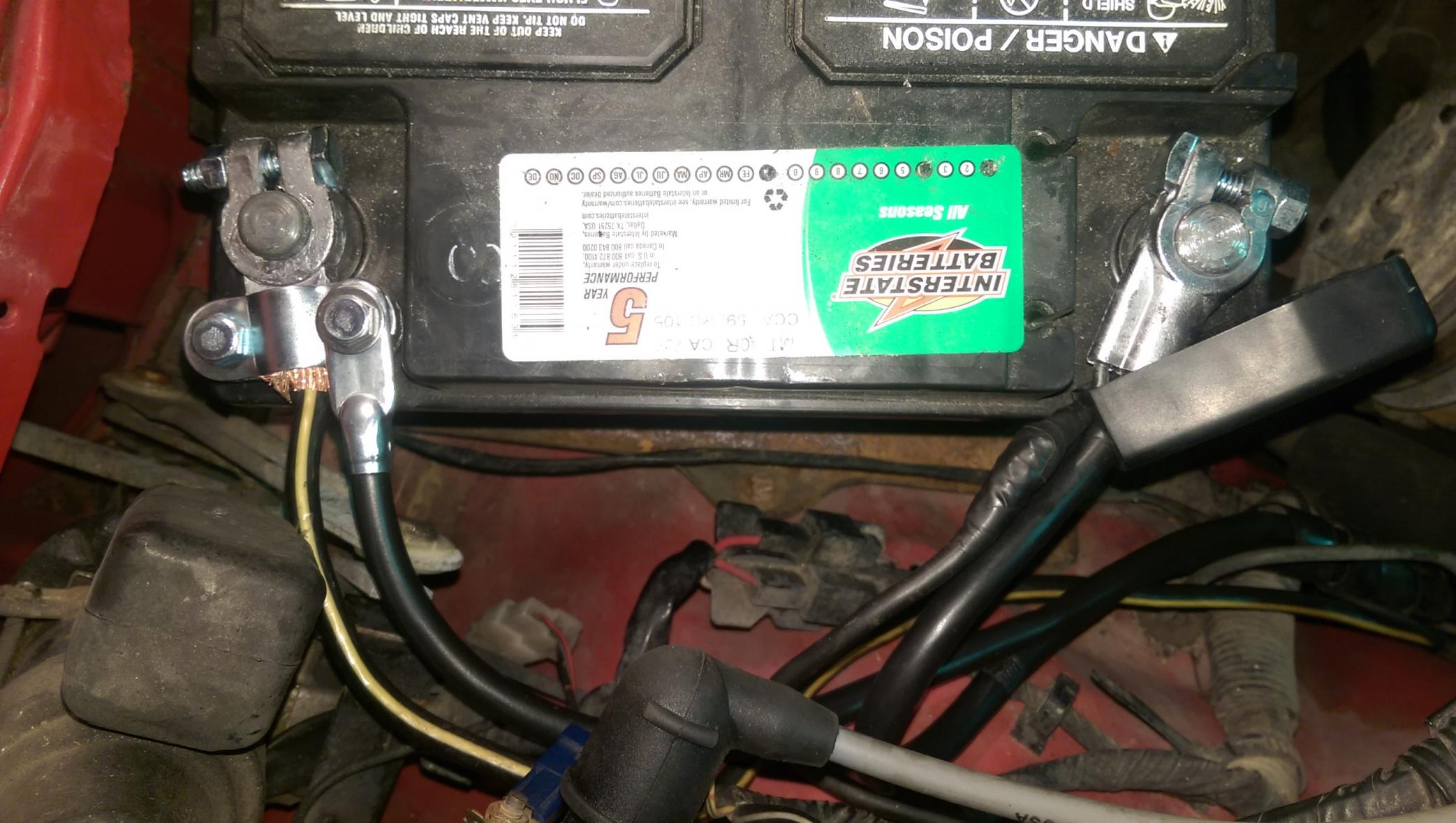
Strut tower chassis ground with new wires running on the bottom of the shot.
New wires running past the steering box and towards their final destinations.
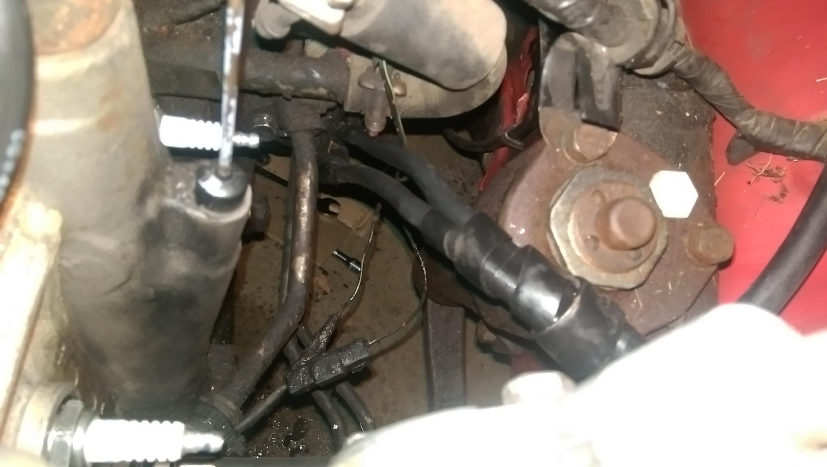
The new cables running down the side of the engine, the positive one's on the starter in this shot. The negative one isn't hooked up yet - see that top hole where there should be a bolt for the tranny? That's where the ground strap bolts to the engine.
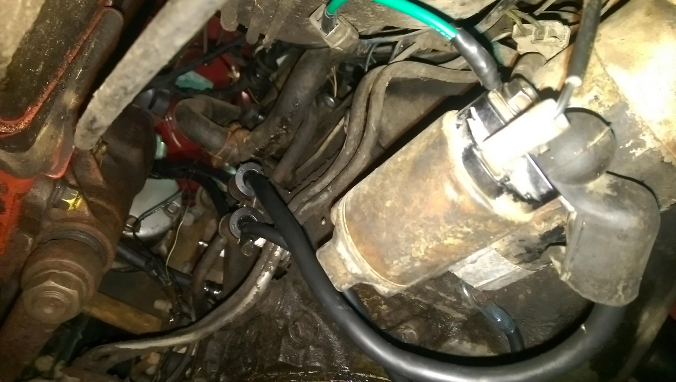
A little better picture of the ground strap location on the side of the engine.
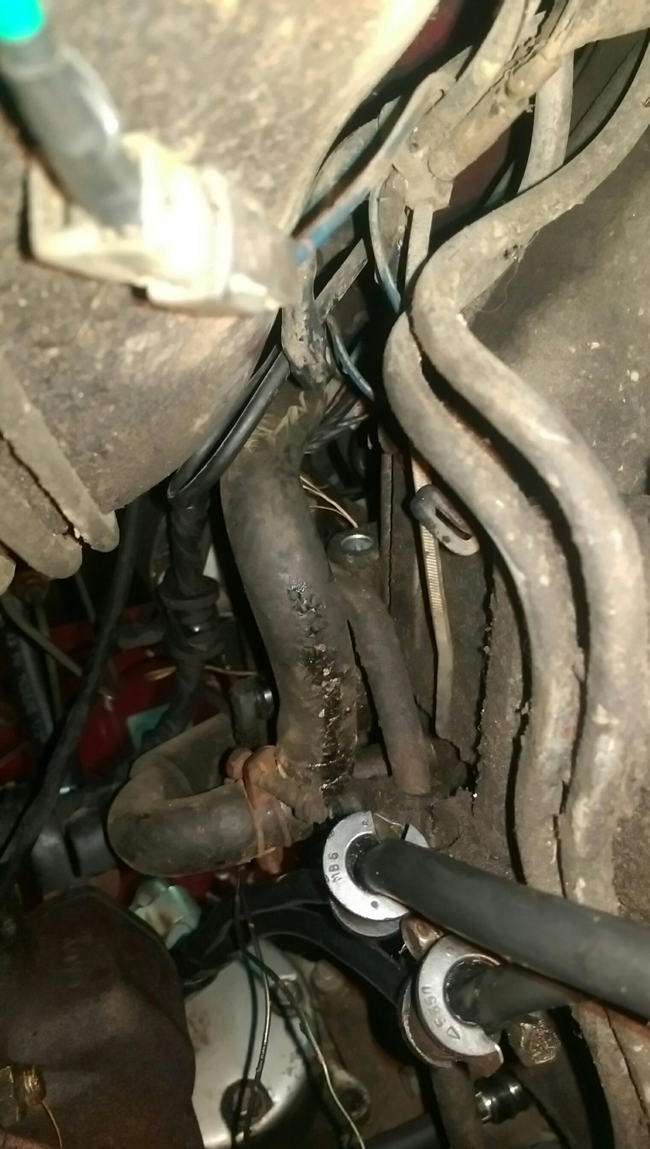
So this procedure did seem to help with the electrical side of things. Feels great to have the cables replaced and know that I don't have to worry about them in the near future.
Needless to say this didn't solve the no-start problem...
01-15-15, 12:33 AM
#5539
I need to rebuild the engine don't I? Might as well start pulling it tomorrow.
01-15-15, 12:34 AM
#5540
Sin City Rotary
Video of the compression of the engine, done the correct way.
1984 Mazda RX-7 - Bad Compression
So I believe that there is a bad apex seal on both rotors based on that test. So engine will have to get pulled and rebuilt if that's correct.
1984 Mazda RX-7 - Bad Compression
So I believe that there is a bad apex seal on both rotors based on that test. So engine will have to get pulled and rebuilt if that's correct.
01-15-15, 01:42 AM
#5541
Originally Posted by DreamInRotary
My bad, they automatically resize for me when I'm on the page - start out ginormous and get smaller after a second. I'll try to resize them before posting next time.
I need to rebuild the engine don't I? Might as well start pulling it tomorrow.
I need to rebuild the engine don't I? Might as well start pulling it tomorrow.
Yes, that engine needs a rebuild. Even if it did fire, it would probably backfire through the carb. Seen that before on an unknown 12A with some broken apex seals, I later discovered during a teardown.
01-15-15, 01:53 AM
#5542
Sin City Rotary
Thanks. My browser doesn't do that and it makes reading posts difficult with all the side scrolling involved. You also can't see details that close up unless the picture is super sharp, which with several distances of objects from the camera, there is always something out of focus.
Yes, that engine needs a rebuild. Even if it did fire, it would probably backfire through the carb. Seen that before on an unknown 12A with some broken apex seals, I later discovered during a teardown.
Yes, that engine needs a rebuild. Even if it did fire, it would probably backfire through the carb. Seen that before on an unknown 12A with some broken apex seals, I later discovered during a teardown.
01-15-15, 10:05 AM
#5543
(Photo mission got pre-empted last night by a chatty neighbor - will try again)
That test vid looks like rebuild time to me, too, if the two tiny pulses are timed to the rotation... the apex seals (or less likely a corner seal) could be bad, or just stuck (carbon or rust), or the springs might have collapsed.
One bad on each makes me think more likely stuck, or spring failure; stored in a wet environment for a long time, moisture from the intake will collect at the bottom of each intake-phase rotor face. Apex seals & their springs don't like water; they rust easily if not oiled, and rusted metal swells.
01-15-15, 10:25 AM
#5544
Thanks. My browser doesn't do that and it makes reading posts difficult with all the side scrolling involved. You also can't see details that close up unless the picture is super sharp, which with several distances of objects from the camera, there is always something out of focus.
Yes, that engine needs a rebuild. Even if it did fire, it would probably backfire through the carb. Seen that before on an unknown 12A with some broken apex seals, I later discovered during a teardown.
Yes, that engine needs a rebuild. Even if it did fire, it would probably backfire through the carb. Seen that before on an unknown 12A with some broken apex seals, I later discovered during a teardown.
I believe it did backfire through the carb once, I found MMO splattered around the air filter and the whole right side of the engine bay a while back after cranking it. So that must have been it backfiring through the carb. Good learning experience to say the least!

I agree, bad apex seal in both rotors is my thought as well. She's going to start to get pulled today - I might even have it completely out if I get a move on. Doing some more garage work today as well too though so that'll get in the way a bit.
(Photo mission got pre-empted last night by a chatty neighbor - will try again)
That test vid looks like rebuild time to me, too, if the two tiny pulses are timed to the rotation... the apex seals (or less likely a corner seal) could be bad, or just stuck (carbon or rust), or the springs might have collapsed.
One bad on each makes me think more likely stuck, or spring failure; stored in a wet environment for a long time, moisture from the intake will collect at the bottom of each intake-phase rotor face. Apex seals & their springs don't like water; they rust easily if not oiled, and rusted metal swells.
That test vid looks like rebuild time to me, too, if the two tiny pulses are timed to the rotation... the apex seals (or less likely a corner seal) could be bad, or just stuck (carbon or rust), or the springs might have collapsed.
One bad on each makes me think more likely stuck, or spring failure; stored in a wet environment for a long time, moisture from the intake will collect at the bottom of each intake-phase rotor face. Apex seals & their springs don't like water; they rust easily if not oiled, and rusted metal swells.
I guess I never thought of that, condensation in the carb and intake would run down and into the housings. And if the car sat for a long time (I don't really know too much history on this car to be honest) without being started or just cranked over then the moisture would just sit and eat away at the apex seal coming up for intake. Thanks for the tip - I wouldn't have thought of that! We do get a lot of condensation here in the spring and fall seasons it seems like, so that would definitely contributed to an apex seal failure if it was sitting.
Since I'll have another 12a manual car coming in about a week that's getting swapped (S4 13bt) then I'm considering testing the compression on that engine and seeing if the motor is good enough to drop into this car. I wanted to do a manual swap anyways and I'd have everything I'd need except a manual pedal set, but I can find one locally from a buddy. The 12a in this car will get torn down and inspected anyways, along with the one already on the engine stand in the garage. I've got a bunch of learning ahead of me at this point!
Scary part is I was told that this engine had 10,000 miles on a rebuild - I hope that means the rotors, housings and irons are still in good or great shape!
DD, Jeff20B, 13x, FM, j9fd3s, 7aull, KCREPU - A HUGE thanks goes out to all of you guys for not just writing me off and ignoring me, I appreciate all the help and advice! I don't know why people complain about this forum all the time and call us the "mean forum" when we have guys like you, thanks a ton!
01-15-15, 11:13 AM
#5545
Moderator
iTrader: (3)
Join Date: Mar 2001
Location: https://www2.mazda.com/en/100th/
Posts: 31,121
Received 2,786 Likes
on
1,972 Posts
i would still get the thing running before you believe the tester.
01-15-15, 01:18 PM
#5546


Looking good, there, FM. I'd like to do the flares and a similar paint job on my '79, but with blue stripes. I don't think I've seen blue. May just stick with the stock red paint, though. Oo! red base with white and grey striping. Need to do a quick photochop and see how that works...
Or I suppose I can go with my first love:

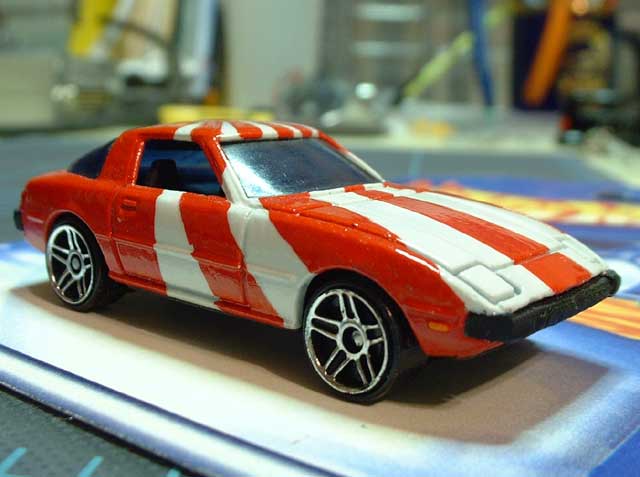
My 85gs is on its way to being a blow-through turbo. Jesus is the man. While he builds real engines, I did this.
It's a 1/3 scale model from the 70's, missing like 10 pieces so it doesn't run on batteries like it should. One of the missing pieces was the Dist cap,
I'm going to see if I can make one, and then I can run the lines and it'll look even better.
Also have a 1/5 scale but it's untouched and all still in plastic bags. Not going to mess with it
I have the Minicraft 1/5 scale twin-dizzy one with light-up spark plugs and such. I built it quite a few years ago, and it's still working. /Needs a new fan belt, though - the black rubber band that came with it is all crispy.
01-15-15, 05:59 PM
#5547
Moderator
iTrader: (3)
Join Date: Mar 2001
Location: https://www2.mazda.com/en/100th/
Posts: 31,121
Received 2,786 Likes
on
1,972 Posts
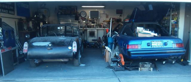
moved peepers on the street to make room for this. part of my evil plans to confuse spiders
01-15-15, 07:08 PM
#5549
Moderator
iTrader: (3)
Join Date: Mar 2001
Location: https://www2.mazda.com/en/100th/
Posts: 31,121
Received 2,786 Likes
on
1,972 Posts