
What did you do to your FB today?

Joined: Jun 2008
Posts: 8,376
Likes: 30
From: Chino Hills, CA
Finished cleaning conformal coating off the back of the ICU circuit board. Will re-coat it with a more modern material once I'm done with it.
Started messing around with castable flexible urethane foam... got me some ideas.
Started messing around with castable flexible urethane foam... got me some ideas.


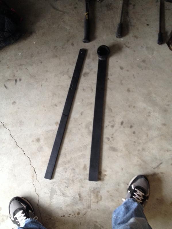
I installed a bunch of nice parts today. Got to test fire it on the gas that was still in the carb. Started right up and ran for several seconds. Success! Next up, get some gas! That empty tank won't fill itself.


Joined: Jun 2008
Posts: 8,376
Likes: 30
From: Chino Hills, CA

GSL-EV
Joined: Jun 2012
Posts: 450
Likes: 8
From: Rapid City, SD
Mentioned adding the heater to my FB to EV conversion. Since the actual heater box is a little small for what I want to do I decided to re-purpose the AC evaporator box. The first photo is the AC evaporator box. The second photo is of the 85 GSL evaporator assembly. It is about 9x8x8 inches. I had never seen one so I thought a photo might interest others. The third photo is of the pair of ceramic heater elements from a couple of $15 space heaters from a discount store. I elected to keep the high temperature plastic to hold the elements, just removing the motors/fans and trimming the housings so the elements are adjacent. I will paint the 1/8" plywood plate to seal the wood and seal the air gaps with high temp silicone gasket material (650 degree F). The last photo shows the assembly sitting in the evaporator enclosure. I need to come up with some way to mount the plywood plate in the enclosure and then fabricate some control electronics to turn it on and off. I've been thinking of doing a quick and dirty PWM and replacing the temperature control with a pot that will control the PWM. I believe the temperature control just changes the amount of hot water that is allowed to flow through the heater core. This may not be necessary and I am hoping it won't be. More updates later. For those who are curious the ceramic cores are a positive temperature coefficient device that when cold draws about 16 amps from a 120vac outlet when first turned on and drops to 10 amps within a few seconds. I expect to see a higher initial current because my battery voltage is 175 volts right off the charge and since I have two elements it should drop off to around 20 amps total giving me about 3500 watts of heat which is about 12000 BTU. This may be excessive and I will have to keep an eye on it. There is an overtemp sensor adjacent to each element which I will use to break the current. Hopefully this happens before the enclosure melts. More later.


Mentioned adding the heater to my FB to EV conversion. Since the actual heater box is a little small for what I want to do I decided to re-purpose the AC evaporator box. The first photo is the AC evaporator box. The second photo is of the 85 GSL evaporator assembly. It is about 9x8x8 inches. I had never seen one so I thought a photo might interest others. The third photo is of the pair of ceramic heater elements from a couple of $15 space heaters from a discount store. I elected to keep the high temperature plastic to hold the elements, just removing the motors/fans and trimming the housings so the elements are adjacent. I will paint the 1/8" plywood plate to seal the wood and seal the air gaps with high temp silicone gasket material (650 degree F). The last photo shows the assembly sitting in the evaporator enclosure. I need to come up with some way to mount the plywood plate in the enclosure and then fabricate some control electronics to turn it on and off. I've been thinking of doing a quick and dirty PWM and replacing the temperature control with a pot that will control the PWM. I believe the temperature control just changes the amount of hot water that is allowed to flow through the heater core. This may not be necessary and I am hoping it won't be. More updates later. For those who are curious the ceramic cores are a positive temperature coefficient device that when cold draws about 16 amps from a 120vac outlet when first turned on and drops to 10 amps within a few seconds. I expect to see a higher initial current because my battery voltage is 175 volts right off the charge and since I have two elements it should drop off to around 20 amps total giving me about 3500 watts of heat which is about 12000 BTU. This may be excessive and I will have to keep an eye on it. There is an overtemp sensor adjacent to each element which I will use to break the current. Hopefully this happens before the enclosure melts. More later.
Pulled motor last week. Stripped motor to the keg and dropped it off to the engine builder. Im excited.
Had to remove bumped to get hoist in. Looks good with no bumper, almost gives me ideas...
Had to remove bumped to get hoist in. Looks good with no bumper, almost gives me ideas...
GSL-EV
Joined: Jun 2012
Posts: 450
Likes: 8
From: Rapid City, SD
I am a little afraid that the ducting will melt at this level. But I have not finalized how I want to hook up the elements. I also have days when I am at work and it is -20F out and I want to be comfortable to drive home before I get home. So that much heating while not needed to keep the passenger compartment warm would help get it there fast.

Joined: Jun 2008
Posts: 8,376
Likes: 30
From: Chino Hills, CA

Joined: Mar 2001
Posts: 31,857
Likes: 3,243
From: https://www2.mazda.com/en/100th/

Mentioned adding the heater to my FB to EV conversion. Since the actual heater box is a little small for what I want to do I decided to re-purpose the AC evaporator box. The first photo is the AC evaporator box. The second photo is of the 85 GSL evaporator assembly. It is about 9x8x8 inches. I had never seen one so I thought a photo might interest others. The third photo is of the pair of ceramic heater elements from a couple of $15 space heaters from a discount store. I elected to keep the high temperature plastic to hold the elements, just removing the motors/fans and trimming the housings so the elements are adjacent. I will paint the 1/8" plywood plate to seal the wood and seal the air gaps with high temp silicone gasket material (650 degree F). The last photo shows the assembly sitting in the evaporator enclosure. I need to come up with some way to mount the plywood plate in the enclosure and then fabricate some control electronics to turn it on and off. I've been thinking of doing a quick and dirty PWM and replacing the temperature control with a pot that will control the PWM. I believe the temperature control just changes the amount of hot water that is allowed to flow through the heater core. This may not be necessary and I am hoping it won't be. More updates later. For those who are curious the ceramic cores are a positive temperature coefficient device that when cold draws about 16 amps from a 120vac outlet when first turned on and drops to 10 amps within a few seconds. I expect to see a higher initial current because my battery voltage is 175 volts right off the charge and since I have two elements it should drop off to around 20 amps total giving me about 3500 watts of heat which is about 12000 BTU. This may be excessive and I will have to keep an eye on it. There is an overtemp sensor adjacent to each element which I will use to break the current. Hopefully this happens before the enclosure melts. More later.
If you think it'll be too much heat, you could wire them so that you can run one or both, and only run one when you don't need as much heat. PWMs a good idea, too, and much more elegant.

