
My Budget Peripheral Port/80mm Turbo/60mm ITB/Intake Manifold/Fuel System Build

Thread Starter
Joined: May 2003
Posts: 1,428
Likes: 0
From: Marion, Ohio
My Budget Peripheral Port/80mm Turbo/60mm ITB/Intake Manifold/Fuel System Build
I've started on my build and gotten a few things accomplished, so I figured I would post some pics and update it as the project progresses.
A bit of background:
I'm a college student that is broke as hell most of the time, albeit mostly because of my car, so I'm trying to do this build as cheaply as possible. I have access to a decently equipped job shop in the factory where I co-op, so I try to make everything I can to cut costs. I cracked a front iron near the end of last season so I figured I would just rebuild the motor using REW irons and add a few extra dowels to it. One thing led to another and now the project has morphed into what you see here.
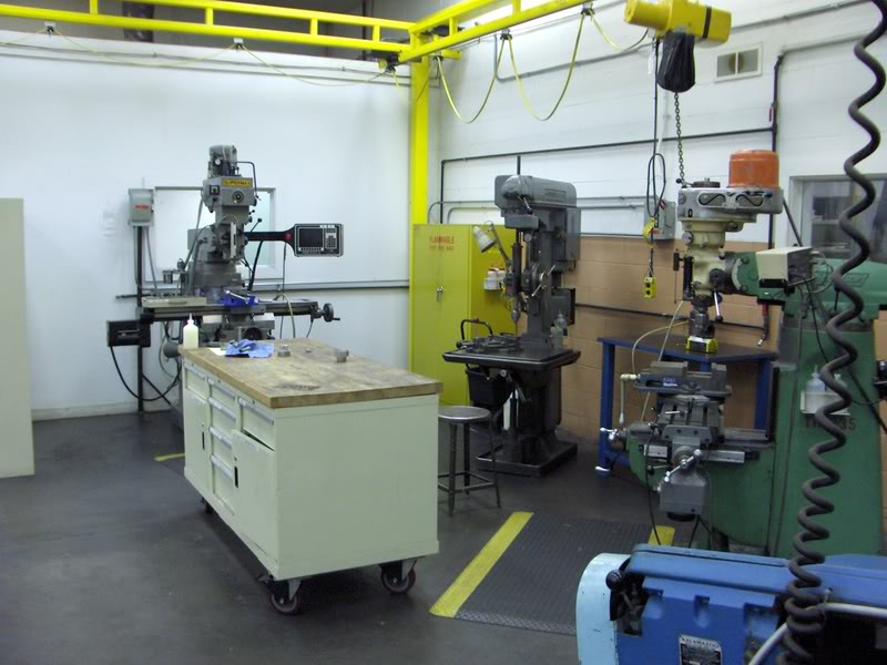
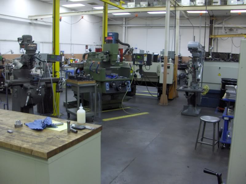
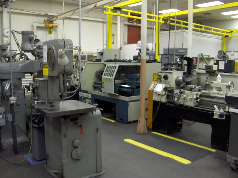
I machine shop I have access to has about everything I need: a few Bridgeports, couple of decent lathes, two CNC mills, a CNC lathe, bandsaws, grinders, a few tracer mills, drillpresses, a heat treating oven, and all the tooling/measurement equipment/fasteners/hand tools. They won't let co-ops use the CNC equipment(I had a hard enough time convincing them I had the skills to run the manual stuff), but the toolmakers are pretty helpful and easily bribed into CNCing stuff for me with doughnuts or malts. They even order tooling I need if they don't have it.
I couldn't reuse the custom intake manifold from the S5 ports, so I decided to go all out with a peripheral port and just make a new intake manifold. I purchased a few used housings and got to work researching PPs. It turns out that there is very little information available about PPs, and the few people who do know about them usually do not want to share their secrets. I decided to just take what I could find and created the design on educated guesses and logic, with a bit of feedback from the helpful fellows over at NoPistons.
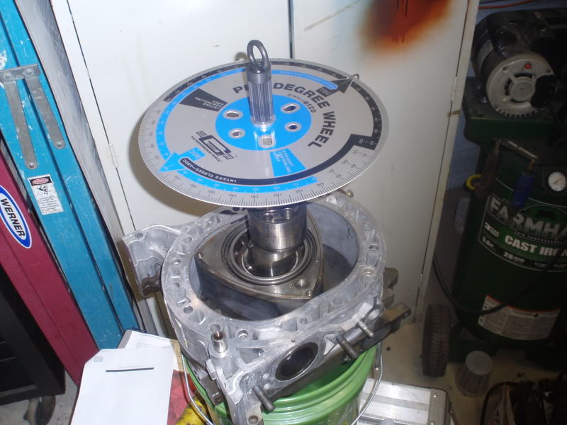
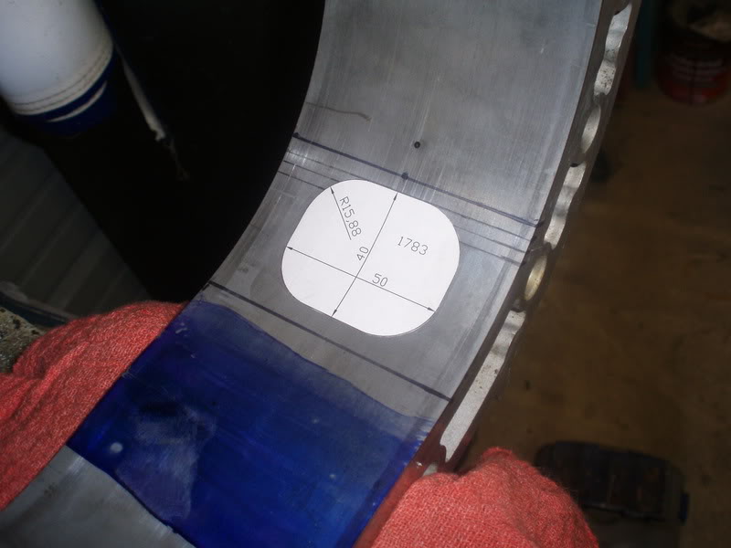
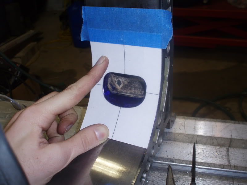
Started out by finding the locations of the port timing I wanted:
Designed port in AutoCAD:
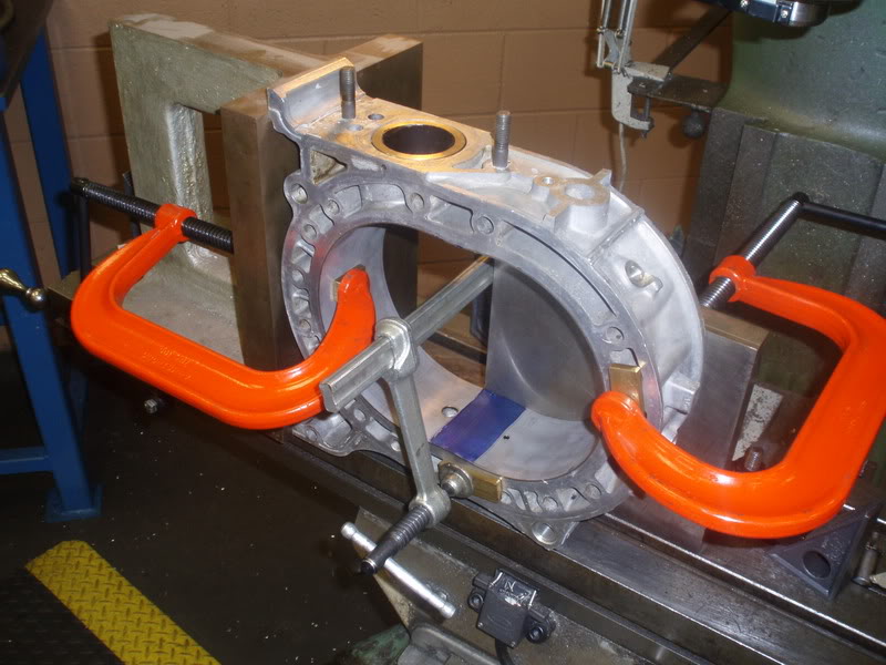
Set up a little jig thingy to locate off of machined surfaces:
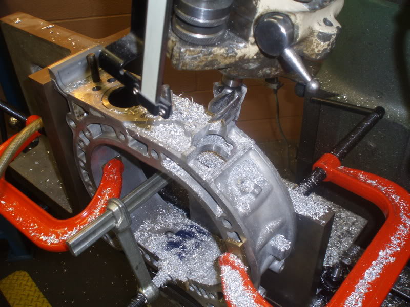
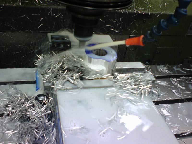
Rough cut the port with a 3/4" carbide rougher:

Finish cut with a 1 1/4" cobalt end mill(the steel insert is TOUGH, it put a few grooves in the cobalt end mill)
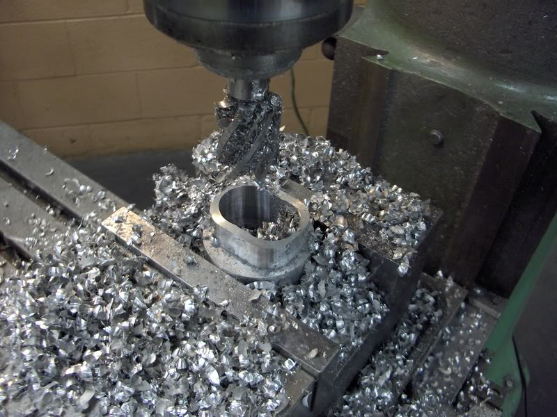
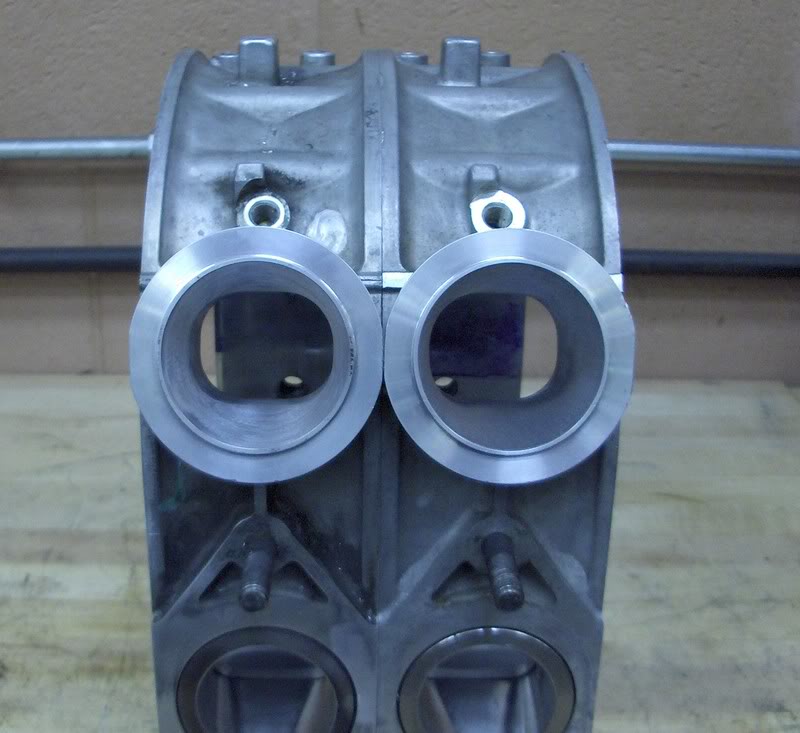
Bored 2.5" dia hole or something partway into the housing concentric with the oval port.
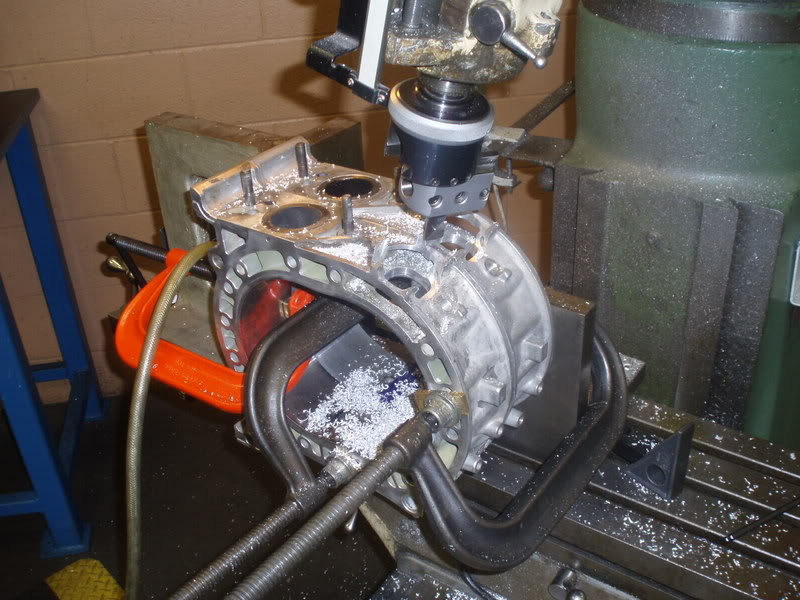
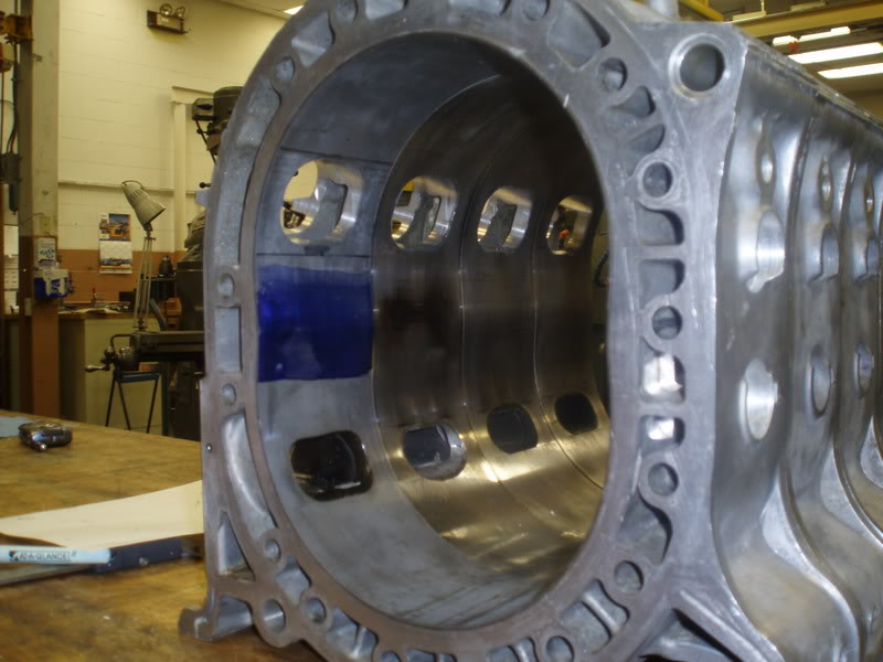
Cutting complete on housings:
A bit of background:
I'm a college student that is broke as hell most of the time, albeit mostly because of my car, so I'm trying to do this build as cheaply as possible. I have access to a decently equipped job shop in the factory where I co-op, so I try to make everything I can to cut costs. I cracked a front iron near the end of last season so I figured I would just rebuild the motor using REW irons and add a few extra dowels to it. One thing led to another and now the project has morphed into what you see here.
I machine shop I have access to has about everything I need: a few Bridgeports, couple of decent lathes, two CNC mills, a CNC lathe, bandsaws, grinders, a few tracer mills, drillpresses, a heat treating oven, and all the tooling/measurement equipment/fasteners/hand tools. They won't let co-ops use the CNC equipment(I had a hard enough time convincing them I had the skills to run the manual stuff), but the toolmakers are pretty helpful and easily bribed into CNCing stuff for me with doughnuts or malts. They even order tooling I need if they don't have it.
I couldn't reuse the custom intake manifold from the S5 ports, so I decided to go all out with a peripheral port and just make a new intake manifold. I purchased a few used housings and got to work researching PPs. It turns out that there is very little information available about PPs, and the few people who do know about them usually do not want to share their secrets. I decided to just take what I could find and created the design on educated guesses and logic, with a bit of feedback from the helpful fellows over at NoPistons.
Started out by finding the locations of the port timing I wanted:
Designed port in AutoCAD:
Set up a little jig thingy to locate off of machined surfaces:
Rough cut the port with a 3/4" carbide rougher:
Finish cut with a 1 1/4" cobalt end mill(the steel insert is TOUGH, it put a few grooves in the cobalt end mill)
Bored 2.5" dia hole or something partway into the housing concentric with the oval port.
Cutting complete on housings:
Thread Starter
Joined: May 2003
Posts: 1,428
Likes: 0
From: Marion, Ohio
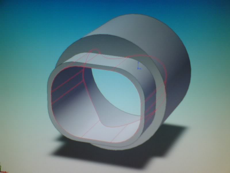
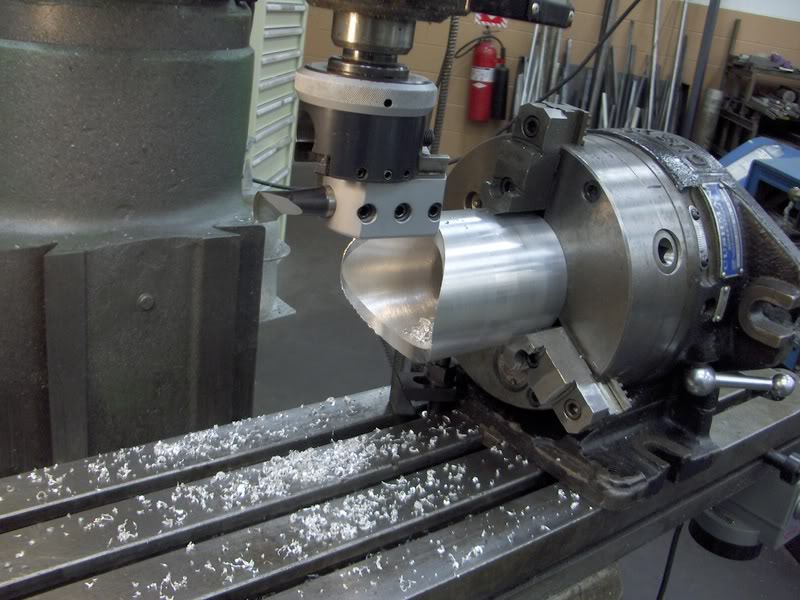
Insert design in SolidWorks:
Machine the inserts:
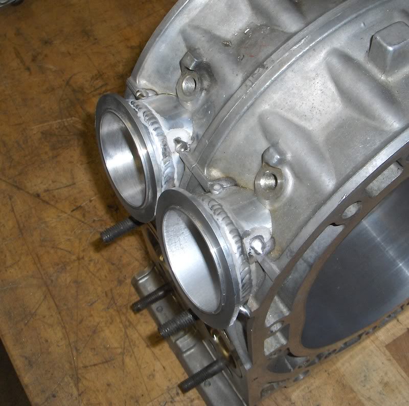
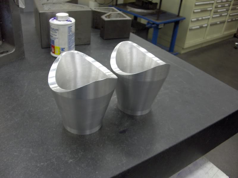
Weld a 2.5" V-band flange to the insert:
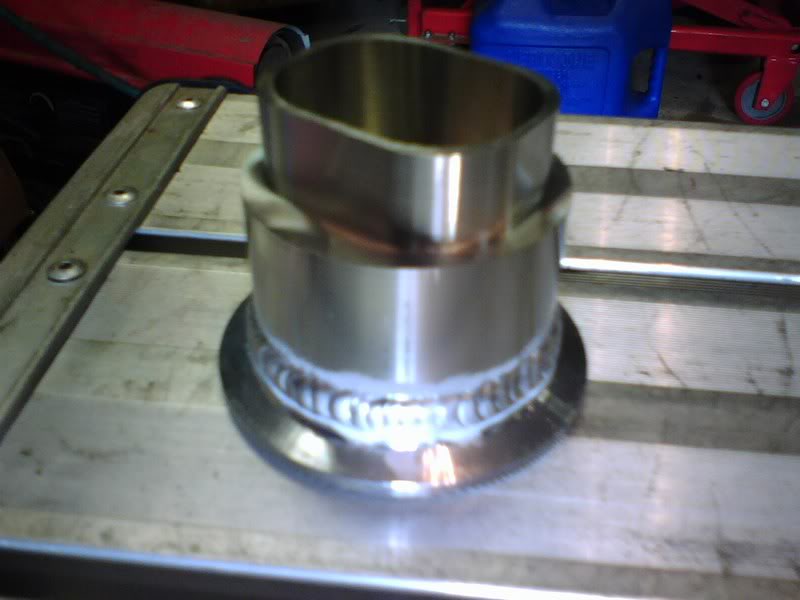
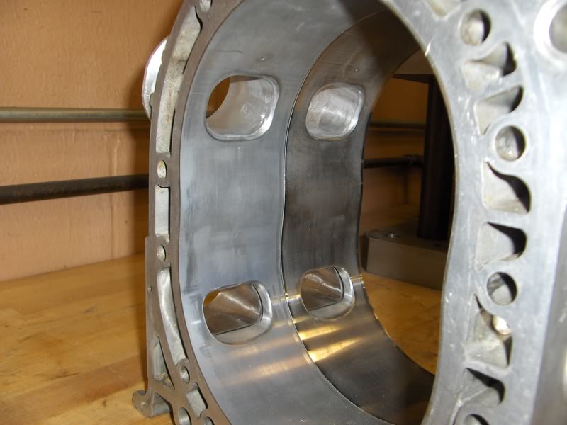
Press the insert into the housing(tight slip fit) and tack weld into place. I smeared a bit of JB weld around the end of the insert to get a better seal. Grind the excess metal down to the steel insert with a slight inward chamfer.

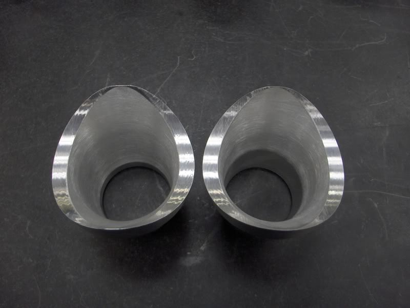
Radius the edges of the port and blend into the insert. A larger radius on the closing edge was added later and can be seen in subsequent pics.
Rough sand inside of inserts:
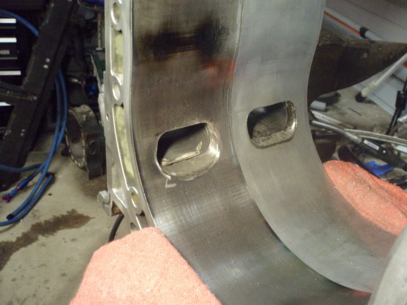
One of the exhaust ports looked like it had been ported with a jackhammer, the other wasn't really so great either. I drew up a port that the drastically different ports could be made into. Not really what I wanted, but I had to make it work. Here are the old ports, they looked a lot worse in real life.
Machine the inserts:
Weld a 2.5" V-band flange to the insert:
Press the insert into the housing(tight slip fit) and tack weld into place. I smeared a bit of JB weld around the end of the insert to get a better seal. Grind the excess metal down to the steel insert with a slight inward chamfer.
Radius the edges of the port and blend into the insert. A larger radius on the closing edge was added later and can be seen in subsequent pics.
Rough sand inside of inserts:
One of the exhaust ports looked like it had been ported with a jackhammer, the other wasn't really so great either. I drew up a port that the drastically different ports could be made into. Not really what I wanted, but I had to make it work. Here are the old ports, they looked a lot worse in real life.
Last edited by DelSlow; Mar 9, 2008 at 12:20 AM.
Thread Starter
Joined: May 2003
Posts: 1,428
Likes: 0
From: Marion, Ohio
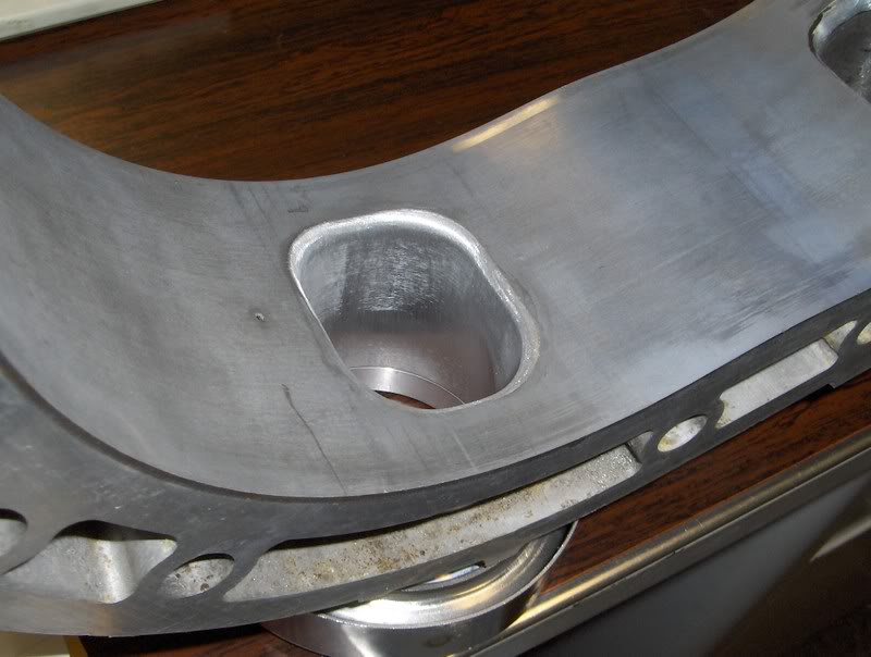
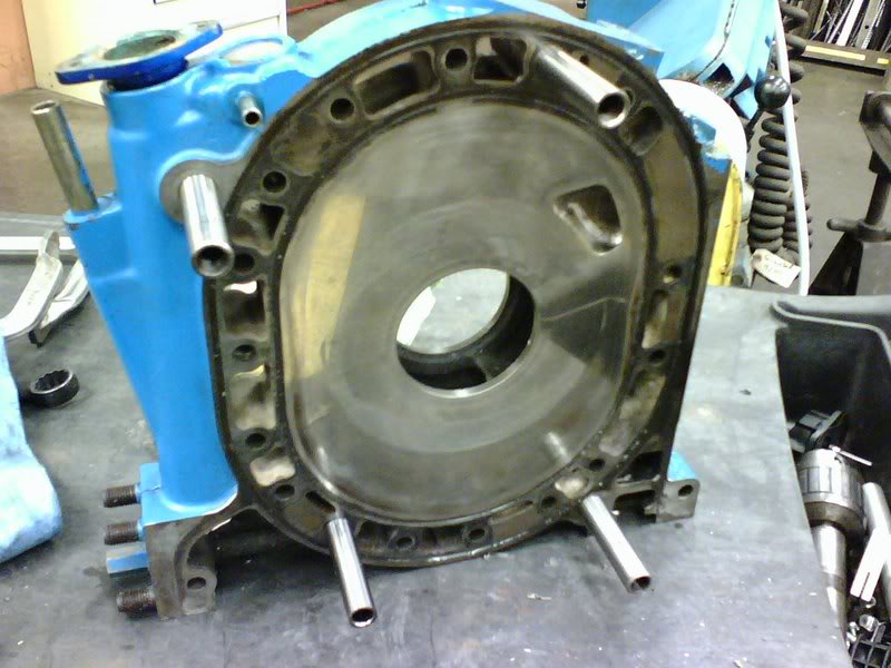
New port design.
Finished ports, couldn't really completely fix the jacked up port, I couldn't get all of the inconsistencies out without taking the port really huge.
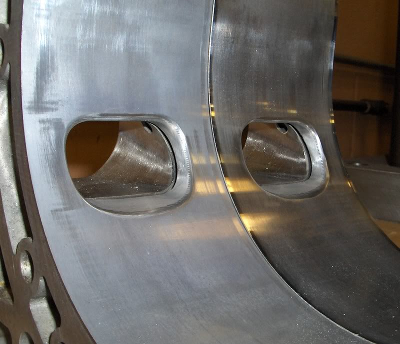
Thats about it for the housings, I may still machine a hole into the top of the ports and put the primary injectors in aiming at the port opening.
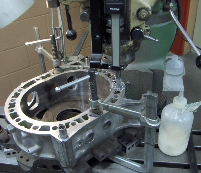
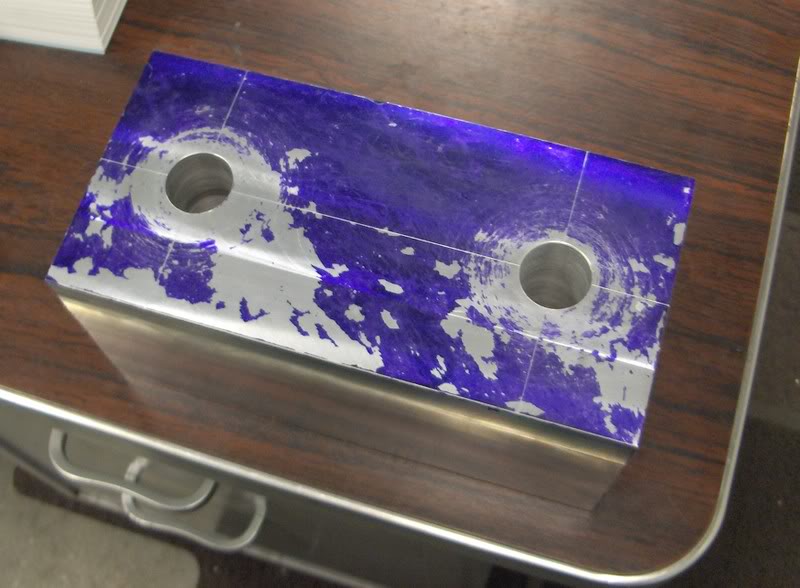
I wanted a add a few dowels to the motor for a bit of extra support, so I had four stock pins center ground down to 15mm (actually 0.0002 under) so there would be more material left in the housings after I drilled them out. I indicated in the start of the hole with a tight slip fit pin into the threads of the front iron. I machined the front half of the motor first, then turned it around and did the other half. I drilled through everything with an end mill first to get everything concentric, then drilled and reamed the holes to size.
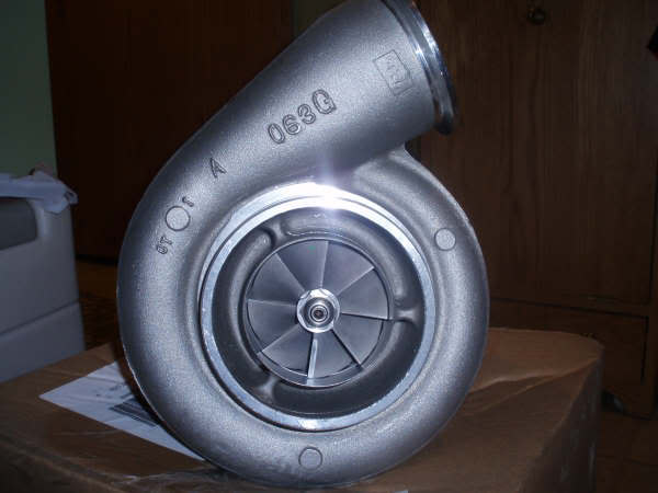
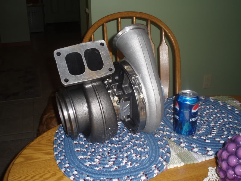
I felt the GT4294 turbine with a 1.01 A/R housing was a bit too small for a peripheral port so I sold it after finding out a larger turbine housing was going to cost like $350 and bought a Borg Warner S480 with a 1.32 A/R housing. I got a great deal on it from Paradise Racing. The compressor housing looks to be about the same size as my GT42, but the turbine appears to be MUCH larger. I haven't actually been able to go home and check it out yet, but I got my mom to take a few pics for me. I will get some better pics next weekend.
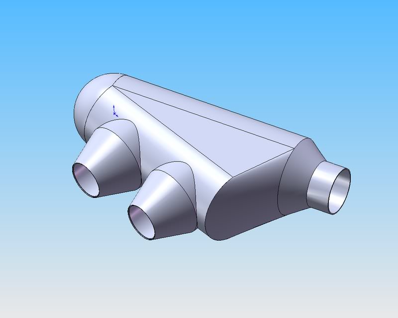
The new intake manifold will be pretty simple. I wanted to make the 2.5" runners as long as possible, so I am using a side feed plenum this time. Plenum will be made from 5" diameter tubing with notched velocity stacks machined from 4" dia billet.
A conceptual drawing done in SolidWorks:
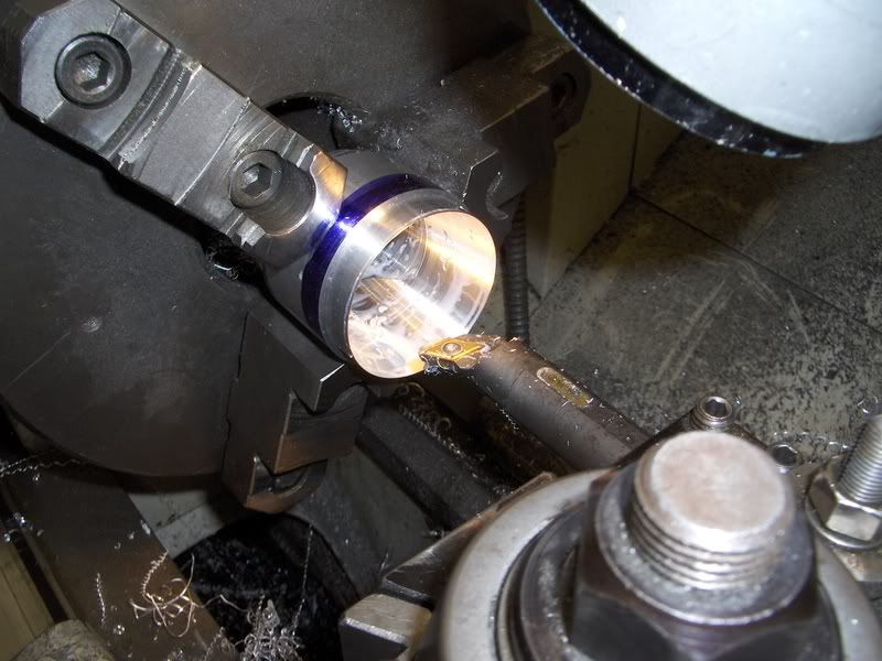
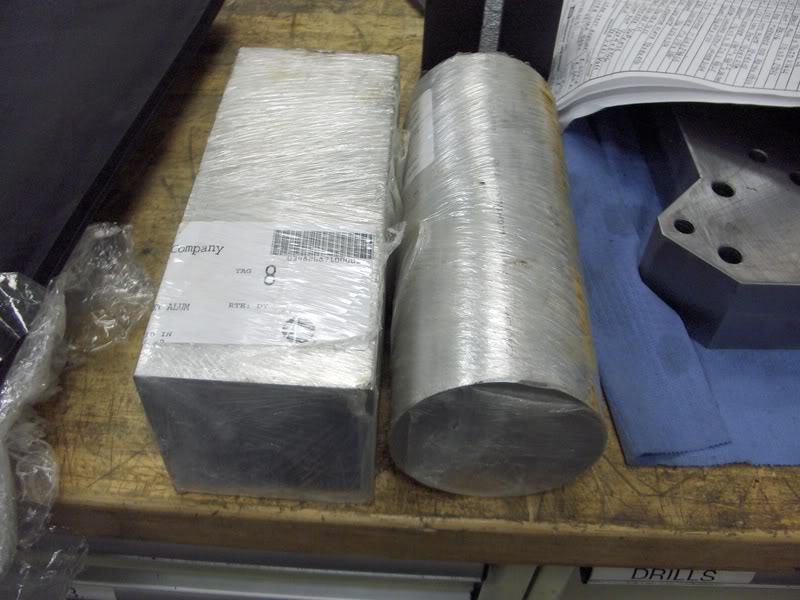
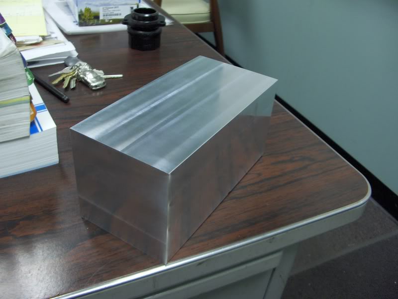
Dropped $140 on two hunks of aluminum for the velo stacks and TBs:
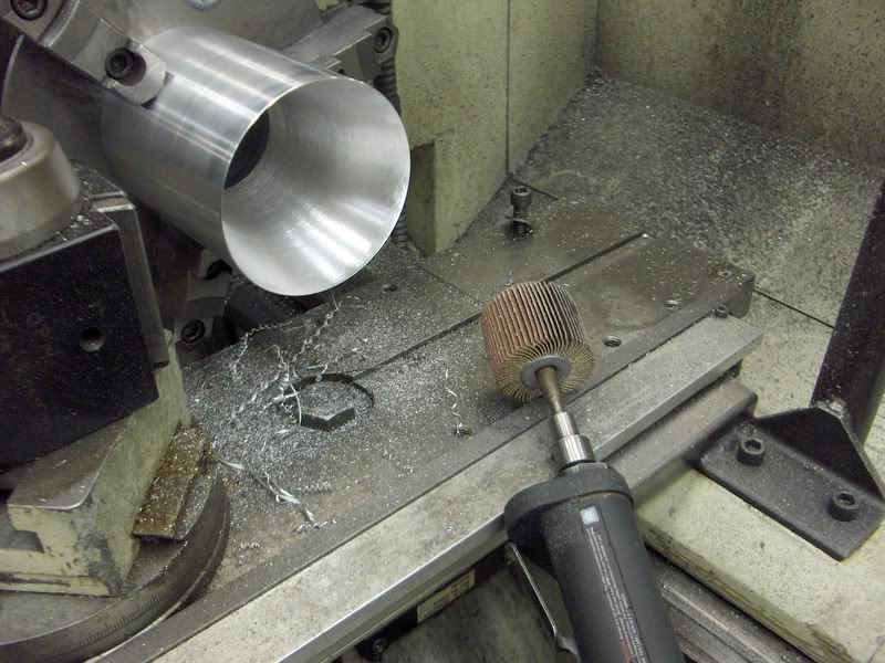
Turning the inside down and sanding:
Finished ports, couldn't really completely fix the jacked up port, I couldn't get all of the inconsistencies out without taking the port really huge.
Thats about it for the housings, I may still machine a hole into the top of the ports and put the primary injectors in aiming at the port opening.
I wanted a add a few dowels to the motor for a bit of extra support, so I had four stock pins center ground down to 15mm (actually 0.0002 under) so there would be more material left in the housings after I drilled them out. I indicated in the start of the hole with a tight slip fit pin into the threads of the front iron. I machined the front half of the motor first, then turned it around and did the other half. I drilled through everything with an end mill first to get everything concentric, then drilled and reamed the holes to size.
I felt the GT4294 turbine with a 1.01 A/R housing was a bit too small for a peripheral port so I sold it after finding out a larger turbine housing was going to cost like $350 and bought a Borg Warner S480 with a 1.32 A/R housing. I got a great deal on it from Paradise Racing. The compressor housing looks to be about the same size as my GT42, but the turbine appears to be MUCH larger. I haven't actually been able to go home and check it out yet, but I got my mom to take a few pics for me. I will get some better pics next weekend.
The new intake manifold will be pretty simple. I wanted to make the 2.5" runners as long as possible, so I am using a side feed plenum this time. Plenum will be made from 5" diameter tubing with notched velocity stacks machined from 4" dia billet.
A conceptual drawing done in SolidWorks:
Dropped $140 on two hunks of aluminum for the velo stacks and TBs:
Turning the inside down and sanding:
Last edited by DelSlow; Mar 9, 2008 at 12:23 AM.
Thread Starter
Joined: May 2003
Posts: 1,428
Likes: 0
From: Marion, Ohio
Notching the velo stacks with a 2.5" radius, I almost broke the $1200 auto-indexing boring head on this when it came unscrewed  because I was running it backwards(had to with the boring tool I was using)
ODs turned down and cutoff:
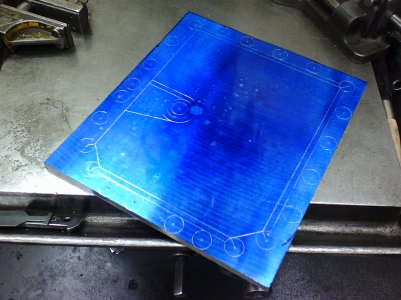
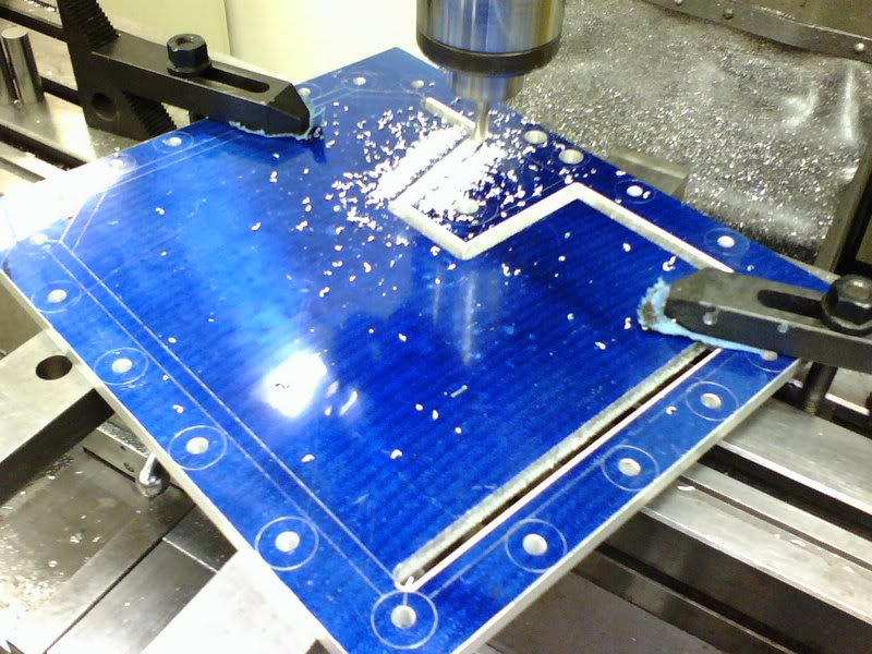
I wanted to make something to strengthen the block externally, so I decided to make a new oil pan. Flange and bottom is made from 1/2" 6061, sides are 1/8" 6061.
Layout:
Machining:
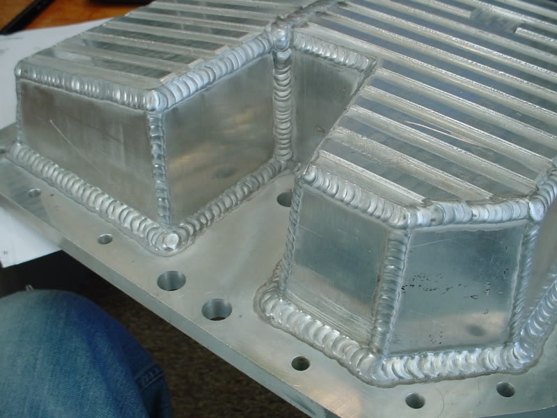
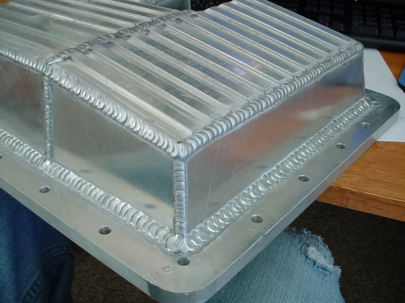
Tacked up:
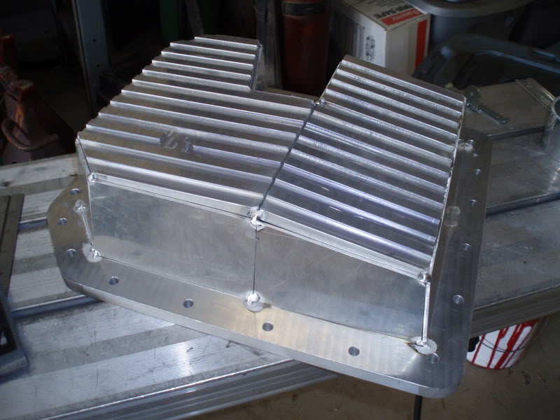
Welded up, still need to add internal bracing, deck it, and drill/tap oil plug hole:
I didn't feel a ported 3rd gen TB was going to cut it this time, so I started looking for a nice big throttle body replacement. The cheapest ones I could find that would work for me were like $250, so I said **** it and am now building a pair of 60mm rotary barrel throttle bodies. The TBs will be machined from a single block of 6061 aluminum.
Squared up and ready to start the real machining:
because I was running it backwards(had to with the boring tool I was using)ODs turned down and cutoff:
I wanted to make something to strengthen the block externally, so I decided to make a new oil pan. Flange and bottom is made from 1/2" 6061, sides are 1/8" 6061.
Layout:
Machining:
Tacked up:
Welded up, still need to add internal bracing, deck it, and drill/tap oil plug hole:
I didn't feel a ported 3rd gen TB was going to cut it this time, so I started looking for a nice big throttle body replacement. The cheapest ones I could find that would work for me were like $250, so I said **** it and am now building a pair of 60mm rotary barrel throttle bodies. The TBs will be machined from a single block of 6061 aluminum.
Squared up and ready to start the real machining:
Thread Starter
Joined: May 2003
Posts: 1,428
Likes: 0
From: Marion, Ohio
Started drilling the holes for the throttle bores, but thats as far as I have gotten so far. Barrels will ride on sealed roller bearings and sealed up with o-rings.
Thats all I've got pictures of for now, I will post updates as the projects progress.
Thats all I've got pictures of for now, I will post updates as the projects progress.

holy $@#^! Nice work man! Just curious..but are you in an engineering major and where do you coop at. I'll be at akron in the fall for mechanical engineering, and sometime id like to coop somewhere.
Trending Topics


Joined: Apr 2002
Posts: 4,232
Likes: 0
From: Rotaryland, New Hampshire
Awesome pics.
One question about the intake manifold, are you worried about diff intake velocities between the two velocity stacks being the way the air enters the plenum?
One question about the intake manifold, are you worried about diff intake velocities between the two velocity stacks being the way the air enters the plenum?
Thread Starter
Joined: May 2003
Posts: 1,428
Likes: 0
From: Marion, Ohio
Absolutely, I am planning on welding the velocity stack and inlet sides of the manifold up separately, then using flow gauges to determine the difference in flow between them. I will then change the plenum as needed, or add internal diverters or whatnot.

1.01 82mm 42R next to a built to spec S400 1.20 A/r 96mm turbine.
Build is looking rather fancy

Looks like you went the same way I did with twin TB's in the runners. Good stuff!
Last edited by Zero R; Mar 9, 2008 at 02:12 PM.


Junior Member
Joined: Jun 2005
Posts: 35
Likes: 0
From: Niagara Falls
Awesome job! You have definetly put a ton of thought and care into your work. You've used all of those nifty machining tricks that really make a decently accurate project into an OC perfection. Those electric zero's on those Bridgeports are a lifesaver. Keep posting pictures!


'Tuna'
Joined: Feb 2001
Posts: 4,637
Likes: 3
From: Miami,Fl,USA
Very nice work.
It's always great when you can do your own custom work and get the results you want.
BTW. Why didn't you turn/machine the v-band attachment as one with the insert instead of making it in a two piece design?

It's always great when you can do your own custom work and get the results you want.
BTW. Why didn't you turn/machine the v-band attachment as one with the insert instead of making it in a two piece design?