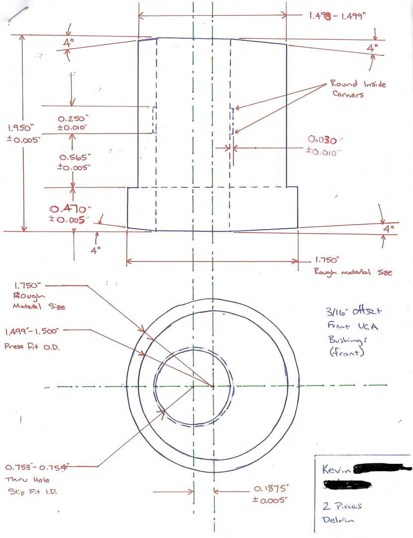
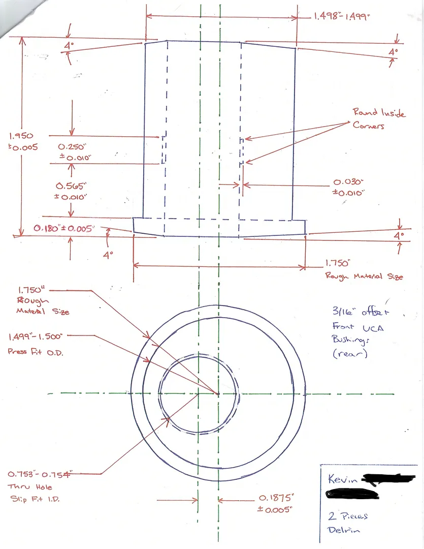
Custom FD front Camber/Caster Bushings
#26
I have some bushings like these for the lower control arms and they worked fine for years. As mentioned I had upper a-arms fabbed since I wanted them adjustable. One thing to bear in mind when doing the uppers is wheel clearance. The Japanese arms shown would likely have issues with large backspace wheels on the rear side of the arm.
-Andy M.
-Andy M.
Or did you pin them somehow to prevent that?
#27
Racing Rotary Since 1983
iTrader: (6)
hey Kevin, congrats on your usual really nice work.
i have been noodling on upper control arms for my FD. i was planning, and probably will go for: chrome moly adj length upper arms for front and rear.
only i want to go the opposite direction.
i plan to run a very low ride height at the Oct Texas Mile. as you know the FD has a ton of negative camber gain on bump. as you lower the car camber goes negative.
there quickly comes a point where you can't dial it out.
my objective is 200 mph and i want zero camber at that speed.
i could just reverse your bushings but would not be able to get anywhere near zero.
i plan two piece uppers in the front w a Right/Left sleeve adj.
howard
#30
Thanks.
And here are the drawings. They're big so you can save them and print with good resolution:
http://i93.photobucket.com/albums/l5.../Bushings1.jpg
http://i93.photobucket.com/albums/l5.../Bushings2.jpg
And here are the drawings. They're big so you can save them and print with good resolution:
http://i93.photobucket.com/albums/l5.../Bushings1.jpg
http://i93.photobucket.com/albums/l5.../Bushings2.jpg
#31
Thanks.
And here are the drawings. They're big so you can save them and print with good resolution:
http://i93.photobucket.com/albums/l5.../Bushings1.jpg
http://i93.photobucket.com/albums/l5.../Bushings2.jpg
And here are the drawings. They're big so you can save them and print with good resolution:
http://i93.photobucket.com/albums/l5.../Bushings1.jpg
http://i93.photobucket.com/albums/l5.../Bushings2.jpg
#32
Senior Member
Join Date: Jul 2003
Location: San Jose
Posts: 291
Likes: 0
Received 0 Likes
on
0 Posts
-Andy
#34
^Looks great! Will you be offering these to some of us track junkies? 
I'm trying to wrap my head around this... how would the alignment change with the SuperPro eccentric pin? Do you mean the pin would spin inside the bushing and change where the offset hole is? Do bushings spin around the pin when the arm is is motion?

I suppose it could. Plus they're a pain in the *** when aligning the car, and if you remove the arm and put it back on, its alignment time. For me, I can remove and install the upper arm and retain the same alignment time after time. Plus its one less thing to worry about.
#41
$250 later I've got some nylatron bushings with stainless inserts. This evening I pressed out the stock pieces and pressed the new ones into place. They appear to fit great. Install into the arms was done in 30-45 minutes using a cheap 5" vice.
I have them clocked as accurately as I could eye-ball... given that the car needs an alignment anyway, will it matter if they're off (from each other) by a few degrees?
I have them clocked as accurately as I could eye-ball... given that the car needs an alignment anyway, will it matter if they're off (from each other) by a few degrees?
#43
Kevin, I installed everything today, thanks again for the awesome idea and accurate diagrams
I'll be taking it for an alignment this week so I have no idea what the camber is right now, however logic would dictate that it's maxed out (because it was prior to the install) and it looks pretty goofy
I might just leave the Hoosiers on all the time so I don't get mistaken for part of the hellaflush crowd
I'll be taking it for an alignment this week so I have no idea what the camber is right now, however logic would dictate that it's maxed out (because it was prior to the install) and it looks pretty goofy

I might just leave the Hoosiers on all the time so I don't get mistaken for part of the hellaflush crowd

#44
Anyone have pictures of these installed on the arms before installing the arms on the car? I had these made and I want to make sure that they are installed in the correct orientation before I installed them on the car. My question is how does the rear bushing installed on the arm? Is the thin flange bushing facing toward the rear on the rear portion of the rear attachment point? See picture for reference.

#45
Anyone have pictures of these installed on the arms before installing the arms on the car? I had these made and I want to make sure that they are installed in the correct orientation before I installed them on the car. My question is how does the rear bushing installed on the arm? Is the thin flange bushing facing toward the rear on the rear portion of the rear attachment point? See picture for reference.

Thread
Thread Starter
Forum
Replies
Last Post
ArmenMAxx
3rd Generation Specific (1993-2002)
17
05-29-23 03:00 PM
Northon Jocelyn
3rd Generation Specific (1993-2002)
4
06-05-10 05:27 AM


