
? about wiring for FJO inj driver

Thread Starter

Joined: Aug 2004
Posts: 4,786
Likes: 146
From: Colorado Springs, CO
? about wiring for FJO inj driver
I got an FJO injector driver and it turned out not to be the one I thought it was. I'm not sure if they upgraded the model or what, but the wiring is different than I thought it was going to be. I had been reading on Damian's fuel kit thread (I think that's the one) and I guess he was using an older model or something cause mine is the KID0404 and I was looking for the KID0004 like he had. Mine has the wires built into the unit instead of the other one that you can disconnect the wiring harnesses from the unit itself.
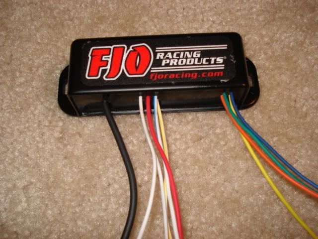
Anyway, with mine it has the 4 solid color wires, 4 white wires with colored lines down the side, the red wire to hook to ignition and black wire for ground. The ground is obvious so I have no problem with that. My problem is the directions say you're supposed to find which wire on each injector that has 12v going to it and the other wire should not have any voltage, but when people hook up resistors it doesn't matter which side you wire them into. So does it matter for the FD or are these directions from FJO just general directions to use on any regular 4 cylinder car?
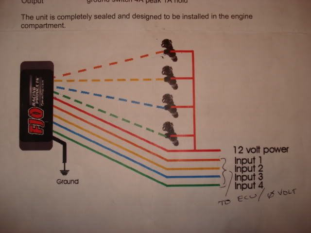
It says you're supposed to connect the colored wires to the wires coming from the ECU (with no voltage), connect the white wires with colored stripes to one side of the injectors and the 12v side of the injectors to the red wire to go to ignition. Am I smoking something or does something just not add up? Each injector clip has two wires, one of each going to the colored wire...so where does the other one connect if the injector is already fully wired in without it? Would someone please enlighten me?
Also, the directions say you're supposed to wire it in with the stock injectors first to make sure it runs properly, did anyone do that or just install them with the new injectors already like I'm trying to do?
Anyway, with mine it has the 4 solid color wires, 4 white wires with colored lines down the side, the red wire to hook to ignition and black wire for ground. The ground is obvious so I have no problem with that. My problem is the directions say you're supposed to find which wire on each injector that has 12v going to it and the other wire should not have any voltage, but when people hook up resistors it doesn't matter which side you wire them into. So does it matter for the FD or are these directions from FJO just general directions to use on any regular 4 cylinder car?
It says you're supposed to connect the colored wires to the wires coming from the ECU (with no voltage), connect the white wires with colored stripes to one side of the injectors and the 12v side of the injectors to the red wire to go to ignition. Am I smoking something or does something just not add up? Each injector clip has two wires, one of each going to the colored wire...so where does the other one connect if the injector is already fully wired in without it? Would someone please enlighten me?
Also, the directions say you're supposed to wire it in with the stock injectors first to make sure it runs properly, did anyone do that or just install them with the new injectors already like I'm trying to do?
I installed the FJO (KID0004) when I removed the resistors from my Bosch 1600.
Never tested with stock injectors. They only mentioned testing with stock injectors for novices who might hosed things up.
Your questions shows that you do not understand basic DCV circuits and should not be doing this mod.
The reistors were in-series current limiting, not device control.
The FJO to the injectors is like an ignition amp to the coils. Same basic idea of using an old output as inout for the new device and the new device uses it's output to replace the old output.
The Mazda FSM section F has the wiring and color codes. All you need is that and a good brain.
!
Thread Starter
Joined: Aug 2004
Posts: 4,786
Likes: 146
From: Colorado Springs, CO
I installed the FJO (KID0004) when I removed the resistors from my Bosch 1600.
Never tested with stock injectors. They only mentioned testing with stock injectors for novices who might hosed things up.
Your questions shows that you do not understand basic DCV circuits and should not be doing this mod.
The reistors were in-series current limiting, not device control.
The FJO to the injectors is like an ignition amp to the coils. Same basic idea of using an old output as inout for the new device and the new device uses it's output to replace the old output.
The Mazda FSM section F has the wiring and color codes. All you need is that and a good brain.
!
Never tested with stock injectors. They only mentioned testing with stock injectors for novices who might hosed things up.
Your questions shows that you do not understand basic DCV circuits and should not be doing this mod.
The reistors were in-series current limiting, not device control.
The FJO to the injectors is like an ignition amp to the coils. Same basic idea of using an old output as inout for the new device and the new device uses it's output to replace the old output.
The Mazda FSM section F has the wiring and color codes. All you need is that and a good brain.
!
Wiring is not my strong point, but I really don't want to mess this up so I'm taking my time to understand exactly what I have to do so I avoid more trouble later. I've done all the modifications to this car myself so far and I'll be damned if I'm going to stop now and let this beat me, I'll just take my time and do it right. And I believe this is better than using just resistors so I'm not going to shortchange my car just because I'm having problems figuring out the wiring. That also doesn't mean I'm just going to throw it in there and hope it works.
So this is what I get so far, correct me if I'm wrong...
Attach black wire to ground, obviously. Find the side of the injector with 0v, cut the wire, splice the colored wires into the ECU side of the wire and the coordinating striped wires into the injector side. Then the 12v side of the injectors (all 4) splice into the red wire. That still leaves 4 wires with 12v coming from the ECU, are they just left to hang? Or are they spliced in with the red wire too?
I did talk to FJO today and they said this is the replacement for the KID0004 (or CID0004 according to their site, making this the CID0404). They said this one is faster, smaller and has less wiring (obviously, haha, that's my problem).
I have the FSM with wiring diagram, and I have a good brain, it's just not wired for wiring haha.
Trending Topics

The wiring for the KID0004 I have no problem with, it's the wiring for this one that's confusing me haha. I know this works different than resistors, what I was saying is that if it doesn't matter which wire you splice the resistor into, I wasn't sure if it would matter which side you splice these wires into, but I understand what you're saying now. I know this is more advanced than simple resistors.
Wiring is not my strong point, but I really don't want to mess this up so I'm taking my time to understand exactly what I have to do so I avoid more trouble later. I've done all the modifications to this car myself so far and I'll be damned if I'm going to stop now and let this beat me, I'll just take my time and do it right. And I believe this is better than using just resistors so I'm not going to shortchange my car just because I'm having problems figuring out the wiring. That also doesn't mean I'm just going to throw it in there and hope it works.
So this is what I get so far, correct me if I'm wrong...
Attach black wire to ground, obviously. Find the side of the injector with 0v, cut the wire, splice the colored wires into the ECU side of the wire and the coordinating striped wires into the injector side. Then the 12v side of the injectors (all 4) splice into the red wire. That still leaves 4 wires with 12v coming from the ECU, are they just left to hang? Or are they spliced in with the red wire too?
I did talk to FJO today and they said this is the replacement for the KID0004 (or CID0004 according to their site, making this the CID0404). They said this one is faster, smaller and has less wiring (obviously, haha, that's my problem).
I have the FSM with wiring diagram, and I have a good brain, it's just not wired for wiring haha.
Since your only using 2 of the 4 channels, you will have 4 wires not connected to anything. You need to use two solid, and the same color stripped wires.
Thread Starter
Joined: Aug 2004
Posts: 4,786
Likes: 146
From: Colorado Springs, CO
Yeah that's cool, I'll let you know and I'll swing up there to help you when you're ready. That's if I can do it myself first haha.
Thread Starter
Joined: Aug 2004
Posts: 4,786
Likes: 146
From: Colorado Springs, CO
I have the old version and it looks like they combined the ignition/power on these all together... a bit simpler.
Red wire off the FJO to the black/yellow wire which all the injectors share (ignition/+).
FJO injector inputs (solid colors) to the PFC injector wires. (LG/R, LG/B, LG/W, LG)
FJO injector output (striped colors) to the injectors; make sure you don't mix up the primaries and secondaries here.
And of course ground to the body.
Edit: The pic you posted and diagram have the wires on different sides...I would go by the wire jacket and not the location on the unit (left or right side). Maybe that's confusing too...
Last edited by PandazRx-7; Aug 26, 2008 at 08:03 PM.
Eric here is my take on the schematic the white with stripe will go to the inj and the solid color will go to ecu
So as per the schematic find the light green/ white wire... cut it the wire leading to the inj connect it to white with yellow and the other end light green /white would be connected to the solid yellow.
This is my opinion and my crappy drawing someone correct me if I'm not seeing it right.
I hope it helps
Thread Starter
Joined: Aug 2004
Posts: 4,786
Likes: 146
From: Colorado Springs, CO
OK I got it now. I hadn't looked at the wiring in the FSM yet so I didn't know the one side of the injectors shared a wire, I thought there was going to be 8 wires coming from the ECU. Thanks guys, and thanks for simplifying it for me Johny haha. That's actually a pretty good drawing.
Thread Starter
Joined: Aug 2004
Posts: 4,786
Likes: 146
From: Colorado Springs, CO
OK as it turns out, I'm still not 100% clear on one thing...I assume I'm supposed to splice the red wire into the 12v wires coming from the PFC as well as the one side of the (4) injectors, is that correct? Otherwise how would it get 12v right? Or do I wire it into a different ignition source? So I would basically connect that side of the injectors to the wires coming from the PFC and then splice the red wire to each one, would that work?
Here we go again damn you wanna be lectricians. J/K
I don't know PFC or fjo but what I see is ONE wire in and one wire out.
THERE IS BLACK AND YELLOW WIRE IT ALREADY HAS 12Volts HOOK THE RED into that wire it is the ONLY place wher you have 3 wires together.
All others are just a single connection.. one wire to one wire.
call me if you want to
I don't know PFC or fjo but what I see is ONE wire in and one wire out.
THERE IS BLACK AND YELLOW WIRE IT ALREADY HAS 12Volts HOOK THE RED into that wire it is the ONLY place wher you have 3 wires together.
All others are just a single connection.. one wire to one wire.
call me if you want to
Thread Starter
Joined: Aug 2004
Posts: 4,786
Likes: 146
From: Colorado Springs, CO
No Johny, I'll have to use new injector clips so both wires on each injector will be clipped. What I'm saying is will I splice the new clips into those wires like normal THEN splice the red wire into that or what? I think that's what I'll end up doing.
Last edited by speedjunkie; Aug 27, 2008 at 10:22 AM.
Yes, *SPLICE* into the BLACK/YELLOW wire with the RED FJO wire... that is where the FJO will gets it's power and so will the injectors still.
Then install the FJO in BETWEEN the ECU and injectors...this is where you cut the PFC injector wires on the harness and connect them to the FJO INPUT wires.
Then run the FJO OUTPUT wires through the firewall grommet and inside the engine bay and crimp on your new clips to the new FJO injector wires. REMEMBER, each injector will have 1 new wire from the FJO and 1 old BLACK/YELLOW wire.
I think that sums it up.
EDIT: Technically you don't even need to run the new FJO wires through the firewall, you can use the existing injector wires you cut on the harness that already go to the injectors. But, if they are crispy near the engine you might as well use the new wires...
Last edited by PandazRx-7; Aug 27, 2008 at 01:26 PM.
Thread Starter
Joined: Aug 2004
Posts: 4,786
Likes: 146
From: Colorado Springs, CO
Cool thanks! Now I just need to figure out which single turbo vacuum diagram to use, I know there are at least 2 running around and there are a few differences between them. I'd post them but I'm on my phone right now.
Last edited by speedjunkie; Aug 27, 2008 at 03:05 PM.
Joined: Oct 2002
Posts: 1,771
Likes: 0
From: Boulder, CO
Did you get this bad boy installed? PM me your number if you figured it out so I can give you a ring some time in the near future. If you help me out I will treat you to some Boulder Chop House, or a few beers with some frisky college girls 
Thread Starter
Joined: Aug 2004
Posts: 4,786
Likes: 146
From: Colorado Springs, CO
Well as it turns out, the guy I got the fuel kit from sold me a primary rail for a damn RX-8, so I haven't even gotten the thing to run yet. I've had fuel leaks and a bracket that won't fit. I'm pretty sure I have it wired in right, as soon as I find out for sure I'll let you know and I'll be up there to help you. Chop House sounds good and the frisky college girls sound DAMN good, but I don't drink so I'll take an extra side of frisky college girls. LOL

Thread
Thread Starter
Forum
Replies
Last Post