
More Airflow and Balanced EGTs from Cosmo Intake

Thread Starter
Joined: Jan 2008
Posts: 438
Likes: 5
From: Ft Worth, Tx
More Airflow and Balanced EGTs from Cosmo Intake
I'm going to try three intake modifications to see if I can squeeze out a little bit more horsepower from my combo and possibly even out the EGTs between the front and rear rotors a bit. On my datalogs, the rear rotor always seems to be between 70 and 100 degrees F hotter than the front. I'm wondering if this is due to the sharp left turn in the intake tract before hitting the TB causing the rear rotor to get more airflow and therefore run leaner. So, I'm going to try three different mods to see how things respond.
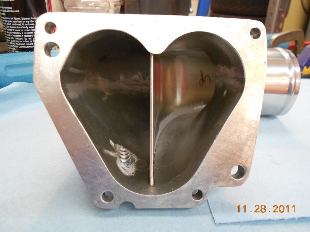
1. Remove the Internal Divider in the UIM - I saw a thread a long time ago where someone suggested removing the center divider in a cosmo intake to make a common plenum for the primary and secondary ports. I think the claim was a little more upper RPM horsepower, but this might also help to even out EGTs.
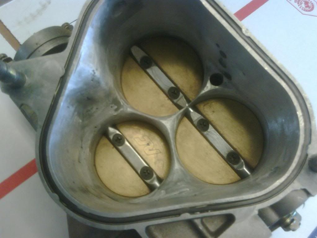
2. Remove the Webbing in the TB - I'm planning to remove the webbing in the TB that was originally there to support the secondary butterflies and blend everything. This shouldn't affect EGTs, but might add a horsepower or two.
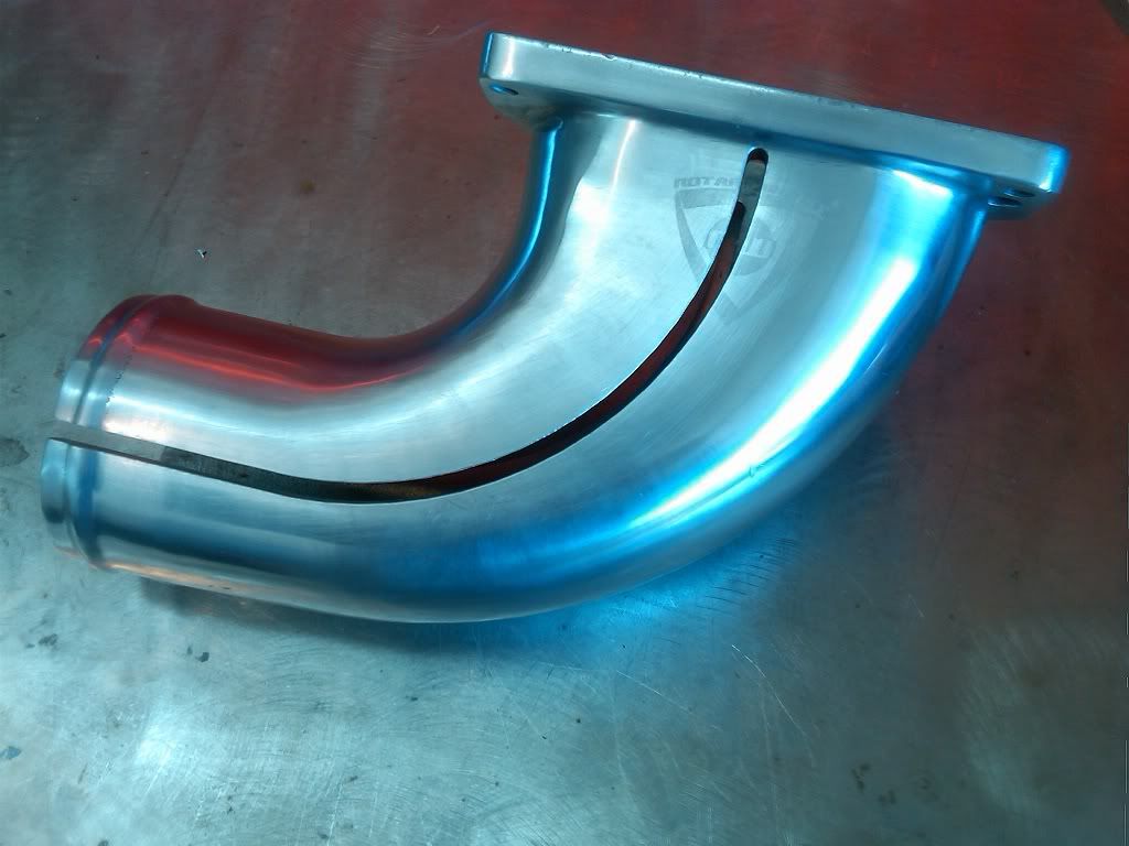
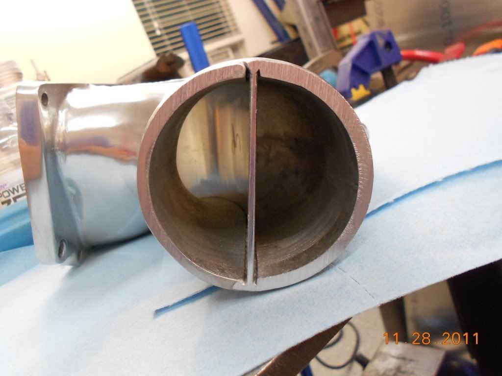
3. Add a Divider in the TB Elbow - Plans are to cut the TB elbow in half and put in a divider to sperate the left and right sides. The thinking is that it will help keep the air from favoring the rear of the elbow and engine due to the left turn. This is a pretty common thing in supercharger air hats, especially for blow through carb setups because the bend to enter the engine is so sharp.
After all of this, I might not gain a damn thing, but anytime you get to cut an intake apart and weld it back together, it's time well spent!
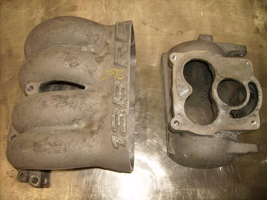
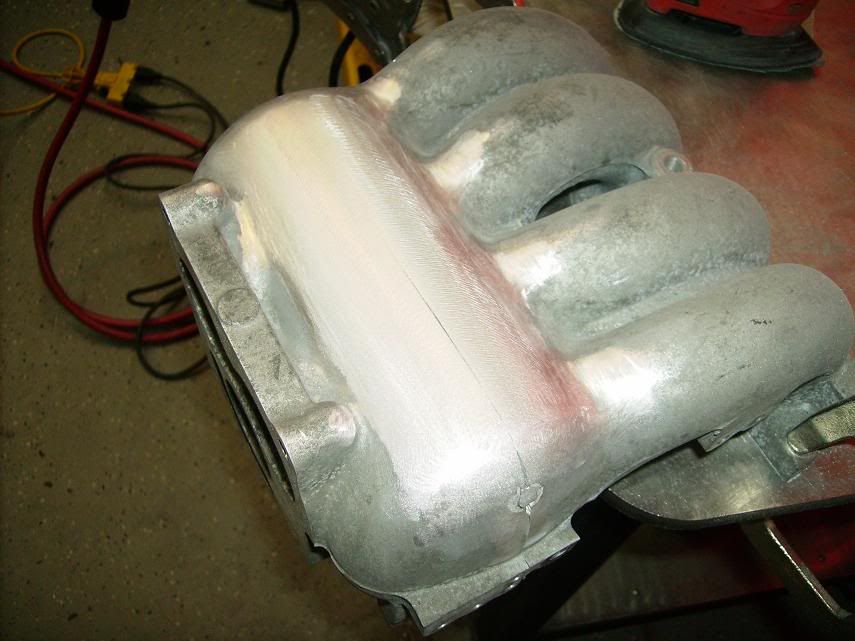
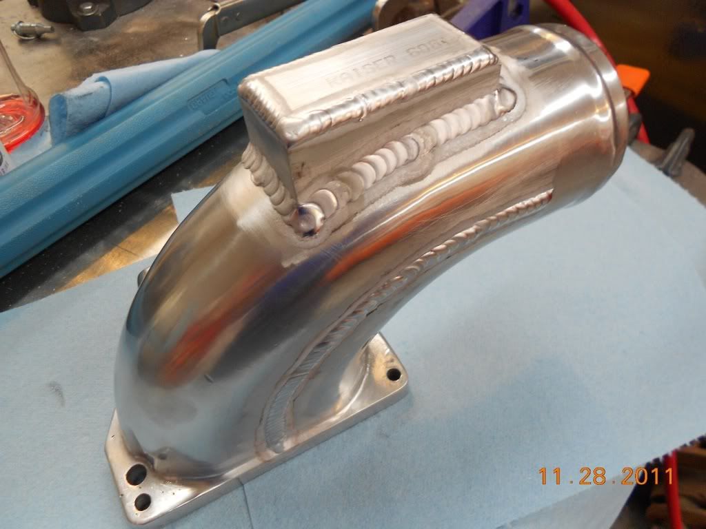
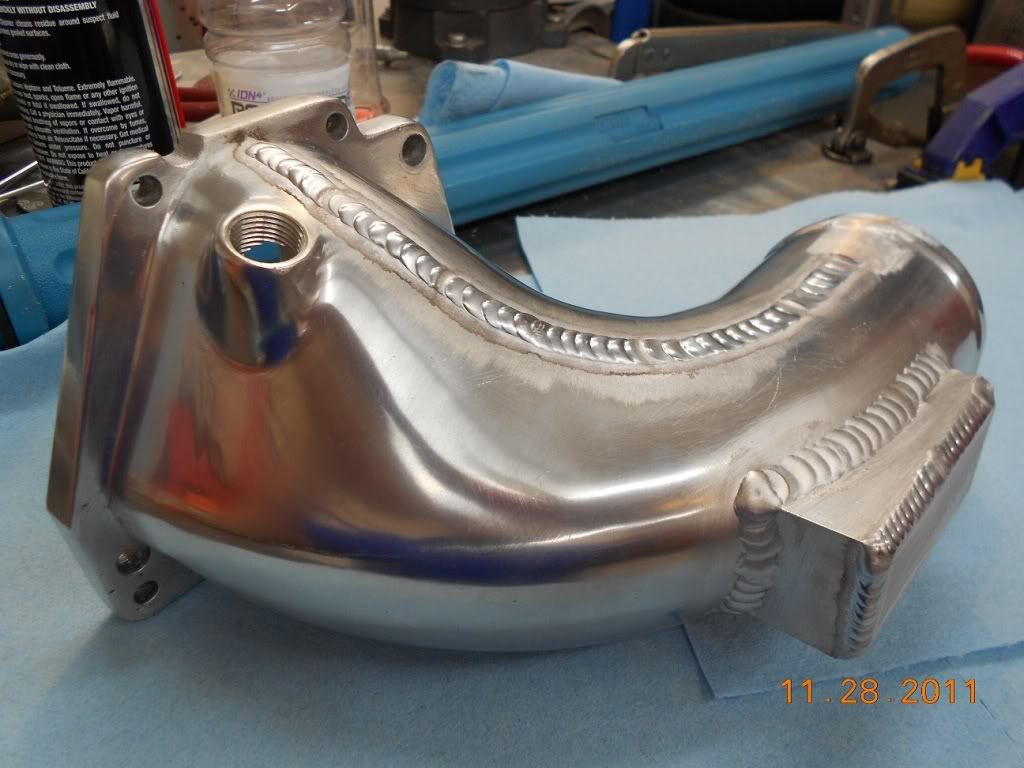
Example of the TB modification.....
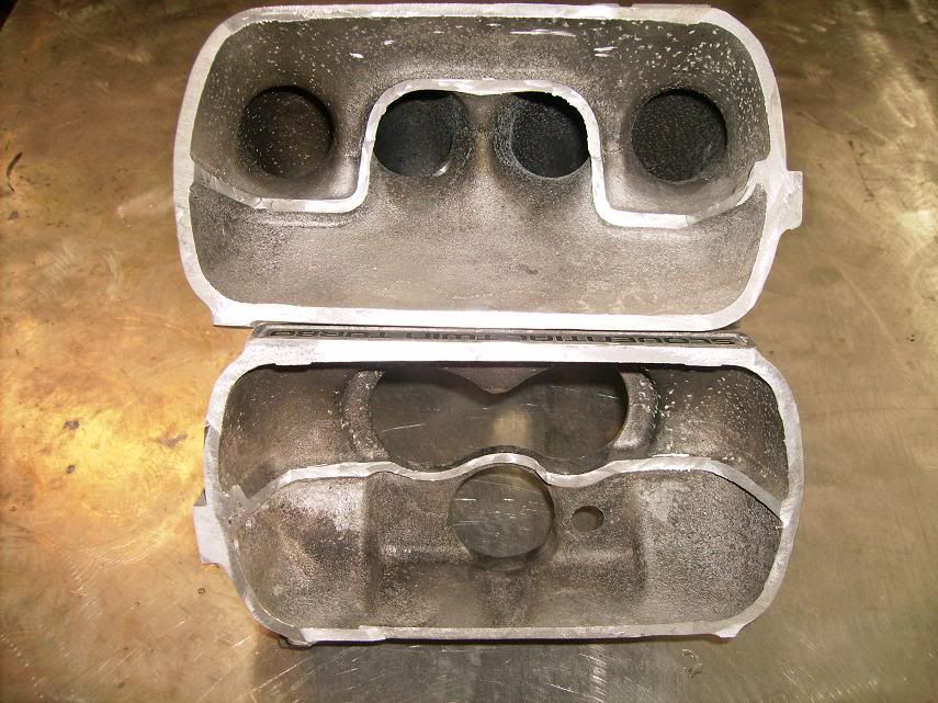
Progress so far.....
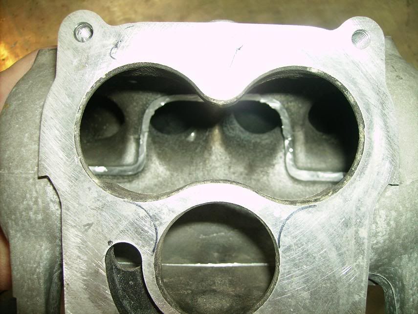
Still have to finish the inside, but I tacked it back together so I could shave the "13B RE" emblem.
1. Remove the Internal Divider in the UIM - I saw a thread a long time ago where someone suggested removing the center divider in a cosmo intake to make a common plenum for the primary and secondary ports. I think the claim was a little more upper RPM horsepower, but this might also help to even out EGTs.
2. Remove the Webbing in the TB - I'm planning to remove the webbing in the TB that was originally there to support the secondary butterflies and blend everything. This shouldn't affect EGTs, but might add a horsepower or two.
3. Add a Divider in the TB Elbow - Plans are to cut the TB elbow in half and put in a divider to sperate the left and right sides. The thinking is that it will help keep the air from favoring the rear of the elbow and engine due to the left turn. This is a pretty common thing in supercharger air hats, especially for blow through carb setups because the bend to enter the engine is so sharp.
After all of this, I might not gain a damn thing, but anytime you get to cut an intake apart and weld it back together, it's time well spent!
Example of the TB modification.....
Progress so far.....
Still have to finish the inside, but I tacked it back together so I could shave the "13B RE" emblem.

In pretty much any motor the rear rotor/pistons/whatever will be hotter than the front. It's because you're moving forward, the fresh air hits the front first, then heats up and hits the rear. There's less cooling to it since there's other stuff in front of it.
Have you made any more progress on this?
Have you made any more progress on this?
Thread Starter
Joined: Jan 2008
Posts: 438
Likes: 5
From: Ft Worth, Tx
Not yet. Hopefully we'll carve out the center of the manifold this weekend.
F**K THE SYSTEM!!
Joined: Sep 2006
Posts: 2,591
Likes: 1
From: Florida
IDK if this is even possible but ill throw it out there. Using a small secondary radiator running off the heater core lines... But mounted for fresh air.. --- would this even bring coolant temps down o the rear of the engine?
good thought log the the egts with the heater off and with the heater on and see if they changes


What people have done in the past isn't add secondary rad, but rather drill and tap another line that goes from the front directly to the rear to provide cooler water temperature to the front instead of just flowing through the first rotor and onto the second. This isn't as big of a problem as say in a 4 rotor. I believe anyone that has one has atleast a fresh supply of water going to the center section of the engine.
Trending Topics
"Elusive, not deceptive!�
Joined: May 2007
Posts: 930
Likes: 13
From: Slidell, LA
My RE has higher front EGT.
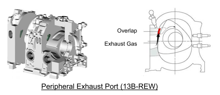
I assume that you changed the exhaust port inserts liners to the REW type.
What does the top of the port look like?
Consider exhaust port closing anti-reversion possibilities.
Barry
I assume that you changed the exhaust port inserts liners to the REW type.
What does the top of the port look like?
Consider exhaust port closing anti-reversion possibilities.
Barry


....I'm wondering if this is due to the sharp left turn in the intake tract before hitting the TB causing the rear rotor to get more airflow and therefore run leaner. ....
....3. Add a Divider in the TB Elbow - Plans are to cut the TB elbow in half and put in a divider to sperate the left and right sides. The thinking is that it will help keep the air from favoring the rear of the elbow and engine due to the left turn. This is a pretty common thing in supercharger air hats, especially for blow through carb setups because the bend to enter the engine is so sharp. ....
....3. Add a Divider in the TB Elbow - Plans are to cut the TB elbow in half and put in a divider to sperate the left and right sides. The thinking is that it will help keep the air from favoring the rear of the elbow and engine due to the left turn. This is a pretty common thing in supercharger air hats, especially for blow through carb setups because the bend to enter the engine is so sharp. ....
A few years ago, as a result of this testing, I devised a simple remedy similar to what you've suggested. Not only does the elbow now properly turn the flow and achieve equal distribution, but the total airflow through the TB (and entire intake tract, for that matter) is also significantly increased--and balanced, at least in the case of the REW. See attached pics.
^ Your flow bench testing is not the best representation of how the air flows inside the manifold because it does not show pulsation effects. I have some information you may find interesting. You can PM me about it.
Thread Starter
Joined: Jan 2008
Posts: 438
Likes: 5
From: Ft Worth, Tx
A few years ago, as a result of this testing, I devised a simple remedy similar to what you've suggested. Not only does the elbow now properly turn the flow and achieve equal distribution, but the total airflow through the TB (and entire intake tract, for that matter) is also significantly increased--and balanced, at least in the case of the REW.
Thread Starter
Joined: Jan 2008
Posts: 438
Likes: 5
From: Ft Worth, Tx
As far as the UIM.....I skimmed the info on pulsation effects. Makes sense in a stock port N/A application. Just wonder how things act with a bridgeport and 20+ psi of boost thrown into the mix. May amplify the effect or may negate it to the point where maximum flow is more important. I'm not smart enough about flow dynamics to theorize on the topic, but I am a good enough fabricator to give it a whirl and see what the old dyno says.
If it does turn out to be a waste of time, and the dynamic pulsation effects are that beneficial in high boost turbo application, just think about all of the horsepower those guys running the 4-bbl throttle bodys and jay-tech intakes are missing out on!
Thread Starter
Joined: Jan 2008
Posts: 438
Likes: 5
From: Ft Worth, Tx
I'll agree that the rear housing runs hotter. I wouldn't think that this would have any effect on EGTs with the ridiculously small amount of time the mixture is in contact with the rotor housing and the temperature difference between the housing/rotor itself (200-300 degrees F) and the ignited mixture (1800+ degrees F). If we assume the front rotor is getting ambient temp coolant (not the case, but whatever) and the rear rotor is seeing the same temp as the thermostat, you are talking about a 100 degrees F difference. When the EGT difference is 70-90 degrees between rotors......there's no way. Has to be the mixture or compression leakage........I probably need to check compression to see if the rear rotor has slightly more cranking compression than the front.
I do think there is validity and benefit to normalizing flow under static conditions, and then working on the dynamic effects for tuning where possible.
In this particular case, there is a significant detrimental effect on overall static flow (and balance) due to the large flow disruption ahead of the throttles. It is severe enough that I suspect that it will have a carryover effect in actual or dynamic operation, hence the effort to do the mod.
I did not test the stock mazda part, it may perform better. Additionally, a simple bonnet with a hard 90* entrance a few inches back from the throttles would likely perform better than the unmodified Greddy piece.
I don't have an EGT history prior to the mod. From what I could gather reading gauge indicated EGT's is that they were pretty consistent front to rear under load, not really enough gauge resolution to say with any certainty that one was higher than the other at full throttle--although there was some difference at idle and light part throttle. (My rear rotor has slightly higher compression, which may account for some discrepancy.)
I agree that static flow testing is not entirely representative of the induction situation, especially concerning tuned effects inside intake manifold and plenum--this is an important distinction. It is a starting point.
I do think there is validity and benefit to normalizing flow under static conditions, and then working on the dynamic effects for tuning where possible.
I do think there is validity and benefit to normalizing flow under static conditions, and then working on the dynamic effects for tuning where possible.
In this particular case, there is a significant detrimental effect on overall static flow (and balance) due to the large flow disruption ahead of the throttles. It is severe enough that I suspect that it will have a carryover effect in actual or dynamic operation, hence the effort to do the mod.
My personal opinion: it makes little difference. The "intake manifold flow balance" issue is a red herring perpetuated by well-meaning intelligent people. Air in the manifold is too busy flowing backwards many times per second for it to matter much. Pulsation effects trump everything, including heat transfer in the manifold, at least up to a point--that's why Mazda spent a gazillion dollars developing the pulsation effects on both the intake and exhaust side of the rotary engine, in both turbo and non turbo applications.
I did not test the stock mazda part, it may perform better. Additionally, a simple bonnet with a hard 90* entrance a few inches back from the throttles would likely perform better than the unmodified Greddy piece.
I don't have an EGT history prior to the mod. From what I could gather reading gauge indicated EGT's is that they were pretty consistent front to rear under load, not really enough gauge resolution to say with any certainty that one was higher than the other at full throttle--although there was some difference at idle and light part throttle. (My rear rotor has slightly higher compression, which may account for some discrepancy.)
Senior Member
Joined: Nov 2008
Posts: 357
Likes: 0
From: Czech republic
Just imagine simple plenum and four runners in there. Primary pulse tuning ends in the place where runners meet plenum. Its plenum and throttle body job to equalize flow and its almost mandatory that flow towards throttle body is steady, otherwise its just havoc.
I strongly believe that pulse tuning can have huge impact on turbo engine, maybe even with bigger magnitude than in NA engine, but flow distribution itself is superior.
To the point of different EGTs, it must lie in difference of airflow. Sure, water enters to the front housing first, but it seems many people forget how coolant flows in RE and also as been pointed out, this alleged difference in temperature can�t account for measured differencies.
With respect, sometimes you get to much caught in technical papers. Pulsation and harmonics are one thing but flow is another and you can separate them.
Just imagine simple plenum and four runners in there. Primary pulse tuning ends in the place where runners meet plenum. Its plenum and throttle body job to equalize flow and its almost mandatory that flow towards throttle body is steady, otherwise its just havoc.
I strongly believe that pulse tuning can have huge impact on turbo engine, maybe even with bigger magnitude than in NA engine, but flow distribution itself is superior.
However I have changed my mind in light of some papers I just read. It is true that the plenum has a dampening effect on pulsation. That's why the FD intake manifold has no plenum.
(Tashima, “Sequential Twin Turbocharged Rotary Engine of the Latest Rx-7,” 1994)
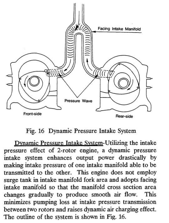
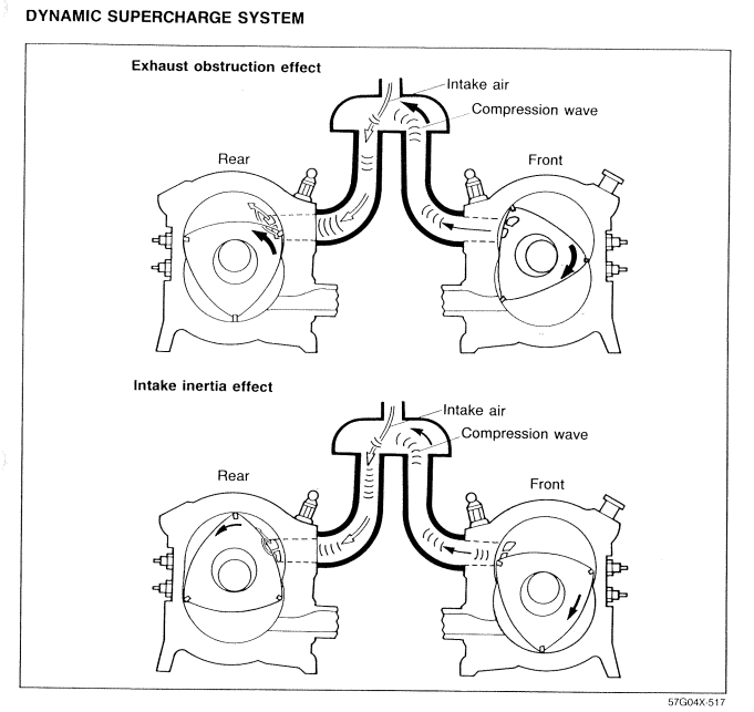
The rotary engine has two major pulsation effects which can also be found to a lesser degree in a piston engine: what Mazda terms the "the exhaust obstruction effect" and "the intake inertia effect."
(1986 FC training manual)
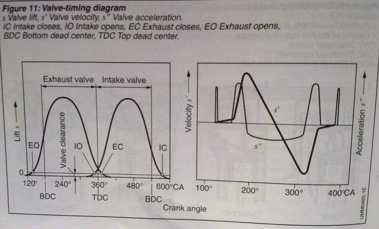
The "exhaust obstruction effect" occurs during overlap of the intake and exhaust stroke. As the intake port opens, the exhaust pressure forces air to first move backwards--when the port opens, air doesn't flow in immediately. The air moves back and is transmitted through the runners and through the plenum (if there is one) all the way to the other rotor just as the intake port is closing. Piston engines have a similar effect but on the rotary it is far stronger because the ports open nearly instantaneously. So here is a valve lift and acceleration diagram on a piston engine:
(Bosch Automotive Handbook 8th edition, 2011)
and here is a port opening area diagram for a rotary engine:
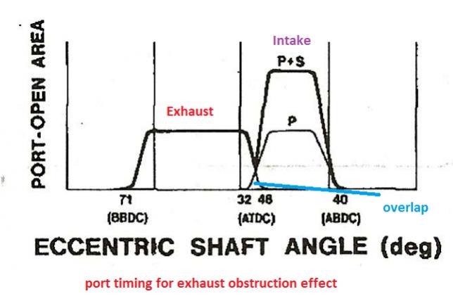
(Okimoto, “Improvement of Rotary Engine Performance by New Induction System,” 1983)
the second effect is the "intake inertia effect," where air moves backwards after colliding with the rotor when the intake port closes. Again, the rotary's ports close so fast that this effect is amplified compared to a piston engine. In fact, the same strong pressure/pulsation effect exists on the exhaust side:
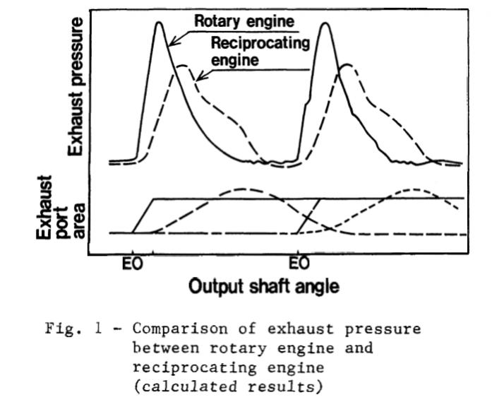
(Tashima, “Development of Sequential Twin Turbo System for Rotary Engine,” 1991)
At full throttle/high rpm there is every indication that a large plenum (really any plenum) actually hurts VE. This was first explored when Mazda was developing the 6 port system:
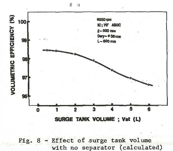
We are kind of jumping all over the place with this discussion. Air is still flowing backwards in the manifold due to pulsation, to a much stronger degree than in a comparable piston engine. A very large single plenum chamber like the OP is proposing might completely eliminate this effect. And that's not necessarily a good thing.
I am now convinced that the FD, s5 n/a and Renesis style design, with reverse-facing runners and no plenum, is superior for high rpm horsepower production. Since the air is moving backwards so often, the total runner length from one rotor to the other is most important, except perhaps when you have a very large plenum. A very large plenum probably worked well on a luxury car application (Cosmo engines) but for what we are doing here it may actually be counter-productive.
The Cosmo, FC turbo, as well as the s3 and s4 non turbo intake manifolds all have a dual plenum-within-a-plenum design where the primary ports and secondary ports have different runner diameters and plenum volumes. I don't have empirical data for this, but I feel strongly that how the air is getting into those plenums (TB elbow) doesn't matter a whole lot except for how it relates to pulsation effects.
To the point of different EGTs, it must lie in difference of airflow. Sure, water enters to the front housing first, but it seems many people forget how coolant flows in RE and also as been pointed out, this alleged difference in temperature can�t account for measured differencies.
The cooling system is actually very sensitive. Mazda had an entire test program in the early days that tweaked the thermostat and the location of tension bolts. This was to change the temperature distribution around the spark plugs and reduce plug-area cracking. Just changing the thermostat design had a big effect on cracking at the spark plug area. This is discussed in Mazda's paper on the 10A engine. It is conceivable that the cooling system primarily accounts for the difference in EGT between rotors, but there's no way to be sure on our end without expensive instrumentation or modeling software.
Senior Member
Joined: Nov 2008
Posts: 357
Likes: 0
From: Czech republic
Ok, several things to consider. Exhaust obstruction effect is on its own detrimental for VE% and Mazda made smart move to counterbalance this bad thing by taking it as certain advantage to increase chamber filling. But what will happen when you fit free flowing exhaust? Its all gone and proper header setup will make it work in conventional manner ie vacuum during overlap pulling fresh air to same chamber. Same with turbo engine when intake pressure is higher than exhaust pressure and in case of BP it should be to take advantage of porting.
I admit that intake inertia effect is interesting one and surely is implemented in Renesis.
My conclusion is, that these effects are rather good example of how to make solid power in somewhat inferior conditions but conventional approach is superior in more favorable conditions. I mean, I haven�t seen factory race engines with such intake style. Also REW maybe utilizes all these effects, but Logan�s testing has shown that for example Cosmo intake doesn�t losses anything in bottom end, has stronger midrage and much better top end. When you look at any dyno chart with REW intake, its clear that it has distinctive peak and then it falls - no good.
Its not black or white
But what will happen when you fit free flowing exhaust? Its all gone
Same with turbo engine when intake pressure is higher than exhaust pressure and in case of BP it should be to take advantage of porting.
I admit that intake inertia effect is interesting one and surely is implemented in Renesis.
I mean, I haven�t seen factory race engines with such intake style.
Also REW maybe utilizes all these effects, but Logan�s testing has shown that for example Cosmo intake doesn�t losses anything in bottom end, has stronger midrage and much better top end. When you look at any dyno chart with REW intake, its clear that it has distinctive peak and then it falls - no good.
What I've been emphasizing here is that the big plenum, big runners, and short (but equal) runner length approach is based around a limited understanding of all the factors and engine dynamics involved.
Its not black or white
I love it when people argue against static flow testing. It becomes very obvious who just reads papers and who actually uses the devices! Keep in mind I'm all for book knowledge and technical specs. I soak it up like a sponge. However flow testing is VERY informative. You need to separate the idea that static flow and the pressure waves inside the manifold are dealt with or tested in the same way. Forget that. Static flow is very important. Balance is what you seek to achieve. Where people go wrong is that they assume more static flow is always better and this is most certainly not true. You only need as much as you need and no more. More that you can use is not better. It's actually worse. You do want a balanced setup though. Keep in mind that not everyone who uses a flowbench uses it properly.
If you have a manifold that flows more to one half of the engine than the other, the returning pulses are going to be stronger on one side than the other. The whole point of them is that they are affecting air flow to a degree and it is an even amount of air flow that we are concerned with.
I know the argument will then be made that you can't compare boosted air to non boosted air in terms of flow. You can reverse the flow on a flow bench, assuming it isn't a piece of crap so you can test for either variable. Traditionally flow testing is done through suction since any heat from the vacuum motor(s) won't affect the air density. When using a flow bench to blow through a manifold you should try to keep it to a shorter amount of testing time as the motors will heat the air up. Good flow bench software does have corrections for temperature but it is best to remove those variables and try to keep things as even as possible.
The rotary is unique due to it's strong pressure pulses. Many people wrongfully state that the rotary intake manifold can reach 3 psi as a result of these pulses. This is a misunderstanding about what was actually being stated in Jack Yamaguchi's book. In the above charts you can see that pressure pulses are short and quick and that there is never a static pressure level present. The positive pressure that "can" be up to 3 psi in the manifold is right at the point immediately before the intake ports close and it is this small spike in pressure late in the intake cycle that can force a small amount more of air to be pushed into the motor. Proper timing is everything and this is where runner length comes into play. The S5 n/a manifold and Renesis manifolds alter this tuned length through the VDI valve to broaden the power band.
All intake manifolds will have the pulsation effect to some point and all manifolds use resonant tuning from the runner itself. One thing you need to realize about runner tuning is that the return wave in the manifold will completely reverse phase and bounce back when it hits a larger area. This means that a runner effectively ends at the plenum. This doesn't mean that the pressure wave doesn't continue though. It does but it has changed phase. This pulse travels at the speed of sound btw and is effected by temperature so changing intake temperature and any heat absorbed by the manifold will affect tuning.
I got off on a severe tangent here and could go on for days but the original jist of this was to say that yes static flow testing is absolutely important and by no means does pressure tuning make flow balance irrelevant. Exactly the opposite. It makes it far more important.
Rotary Enthusiast
Joined: Jun 2004
Posts: 862
Likes: 0
From: Austin TX.
my change for the TB elbow
around 10yrs ago i studied that factory and grddy replacement, just did nt seem right for flow and theory pulses.
so i made up this affair ,it has a nice shaped air horn inside the plenum , plus the usual polishing and removing someother useless crap, and a couple manifold mods .
response is great for me blows the 555Rs off in second and third.
so i made up this affair ,it has a nice shaped air horn inside the plenum , plus the usual polishing and removing someother useless crap, and a couple manifold mods .
response is great for me blows the 555Rs off in second and third.
What you should do is get rid of that throttlebody and use a FD unit. I cut mine open but did it a little differently. These pics weren't the final product, it was such a pain in the ***, I don't think I would ever do that again in my life. Haven't finished the car yet so I don't have any results...