
Latest Experiment…Failure!

As an update the "failure".... it is still running 3 years later. I do have to re-Loctite the spark plug at each replacement.
The latest experiment is with the in-chamber sensor where we just broke 1000 psi chamber pressure for the first time (10 lb wastegate spring goes to 12psi).

The latest experiment is with the in-chamber sensor where we just broke 1000 psi chamber pressure for the first time (10 lb wastegate spring goes to 12psi).
Barry I've been in discussion with another forum member as to the potential combustion pressures inside the rotary during a water steam clean. Would you be interested in performing such a test?
-J
Thread Starter
"Elusive, not deceptive!”
Joined: May 2007
Posts: 930
Likes: 13
From: Slidell, LA
Quote:
Originally Posted by t-von
Barry I've been in discussion with another forum member as to the potential combustion pressures inside the rotary during a water steam clean. Would you be interested in performing such a test?
And t-von, I am a little afraid to turn off the water! But what test do you suggest?
So far we have looked at advanced timing and split.
Barry
Originally Posted by t-von
Barry I've been in discussion with another forum member as to the potential combustion pressures inside the rotary during a water steam clean. Would you be interested in performing such a test?
So far we have looked at advanced timing and split.
Barry
Thread Starter
"Elusive, not deceptive!”
Joined: May 2007
Posts: 930
Likes: 13
From: Slidell, LA
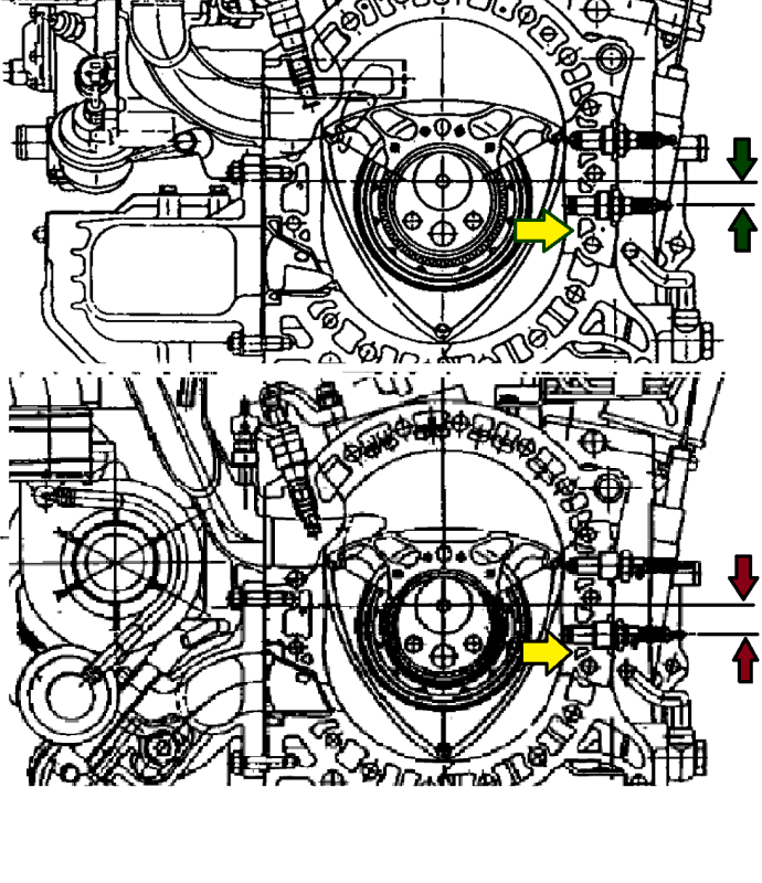
A little update with pictures.
The main reason for the housing bump (and subsequent breaking or warping of apex seals) is the problem of high spark plug temps.
Ironically the problem was worsened by an "improvement" to the later production engines.
Understanding this leads to a solution (or a least the method to mitigate the temps).
Mazda publishes very accurate diagrams. This one shows a 13B improvement of moving the leading plug further from the trailing to help increase burn-rate.
Unfortunately this decreases the size of the most critical water passage in the engine (see yellow arrow).
Back to the solution. All we have to do is recreate Mazda's original size passage without getting any closer to the plug casting area.
Barry

Joined: Mar 2001
Posts: 31,833
Likes: 3,232
From: https://www2.mazda.com/en/100th/
i was too lazy to go find it again, but there is a photo gallery somewhere of this http://www.youtube.com/watch?v=mzJGFBJlJrc
i'd suggest you copy THOSE, as that engine without the restrictor is making substantial HP on pump gas, and it goes a long time between rebuilds. it gets a lot of miles too, i've seen it run at laguna almost every year since 2001...
i dig the 4 rotor seal case
i'd suggest you copy THOSE, as that engine without the restrictor is making substantial HP on pump gas, and it goes a long time between rebuilds. it gets a lot of miles too, i've seen it run at laguna almost every year since 2001...
i dig the 4 rotor seal case
Thread Starter
"Elusive, not deceptive!”
Joined: May 2007
Posts: 930
Likes: 13
From: Slidell, LA
Man-o-man, Do I feel slow. I have half the number of parts and those guys build the 4 rotor in thirty seconds.
I wonder if those housings are cut at the through bolts and only supported by the plug bosses?
Barry
I wonder if those housings are cut at the through bolts and only supported by the plug bosses?
Barry
i was too lazy to go find it again, but there is a photo gallery somewhere of this http://www.youtube.com/watch?v=mzJGFBJlJrc
i'd suggest you copy THOSE, as that engine without the restrictor is making substantial HP on pump gas, and it goes a long time between rebuilds. it gets a lot of miles too, i've seen it run at laguna almost every year since 2001...
i dig the 4 rotor seal case
i'd suggest you copy THOSE, as that engine without the restrictor is making substantial HP on pump gas, and it goes a long time between rebuilds. it gets a lot of miles too, i've seen it run at laguna almost every year since 2001...
i dig the 4 rotor seal case
Joined: Mar 2001
Posts: 31,833
Likes: 3,232
From: https://www2.mazda.com/en/100th/
from http://www.autoblog.com/2011/05/20/m...anniversary-o/
i swear there was a pic where you can see the reliefs, but i can't find it, maybe you have to pause the video?
i swear there was a pic where you can see the reliefs, but i can't find it, maybe you have to pause the video?

Full Member
Joined: Nov 2003
Posts: 192
Likes: 8
From: .
I'm going to give this a go and see if it helps cure the leading plug high spot. I hope to make 600rwhp on pump gas initially, then ultimately 700rwhp, probably on E85.
Also, I enlarged the gallery below the leading plug as barry mentioned.
Also, I enlarged the gallery below the leading plug as barry mentioned.
Me and my engine builder are going to use some of these ideas on a p-port turbo motor we're building. We really like the idea of running cooling lines to the rear plugs coming off the water pump. Only thing is that it makes more sense to run two individual lines instead of teeing off one line.
Also, if eliminating boiling at the rear leading plug is one of the objectives I'm surprised no one has brought up Evans NPG coolant. Evans has a boiling point of 380F and should eliminate the problem of boiling at the rear leading plug.
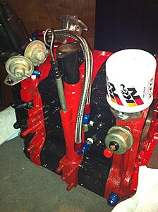
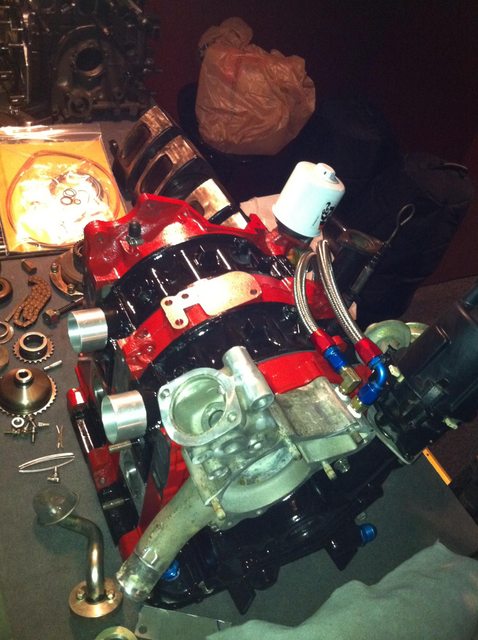
I think everyone is coming up with some great ideas here and I hope others can contribute more to solving this coolant problem. Here are some pictures of the coolant lines me and my engine builder ran to the rear plugs.

Also, if eliminating boiling at the rear leading plug is one of the objectives I'm surprised no one has brought up Evans NPG coolant. Evans has a boiling point of 380F and should eliminate the problem of boiling at the rear leading plug.
I did on page 1
I run Evans NPG+ in a zero pressure system and it really helps eliminate minor leaks and its properties should alleviate the problems of lack of heat transfer at the plugs due to vapor barrier.
Like you, I believe the cooling problem being addressed here is caused by a localized hot spot that exceeds the vapor pressure of the coolant used and the resulting vapor deposition on the rotor housing walls inhibits heat transfer.
However, some tracks only allow water in the cooling system as a safety measure.
So you just drilled and tapped next to the plugs?
Me and my engine builder are going to use some of these ideas on a p-port turbo motor we're building. We really like the idea of running cooling lines to the rear plugs coming off the water pump. Only thing is that it makes more sense to run two individual lines instead of teeing off one line.
Also, if eliminating boiling at the rear leading plug is one of the objectives I'm surprised no one has brought up Evans NPG coolant. Evans has a boiling point of 380F and should eliminate the problem of boiling at the rear leading plug.
I think everyone is coming up with some great ideas here and I hope others can contribute more to solving this coolant problem. Here are some pictures of the coolant lines me and my engine builder ran to the rear plugs.
Joined: Mar 2001
Posts: 31,833
Likes: 3,232
From: https://www2.mazda.com/en/100th/
coolant is very slippery! [band camp] this one time i was behind a new turbo porsche on the track, and it blew a hose off, and as soon as stuff hit the windshield the car was sideways, in a straight away [/band camp]
This is a drag motor which consequently won't see that much run time. Because of this I'm not worried about corrosion. That and there is a ton of pipe dope and Teflon tape acting as a barrier.
Joined: May 2005
Posts: 2,745
Likes: 0
From: North Bay, Ontario
I forgot how much I liked this thread, what's new Barry?
Old [Sch|F]ool


Joined: May 2001
Posts: 12,862
Likes: 568
From: Cleveland, Ohio, USA

People don't freak out about putting special goops on bolts when they put their intake manifolds together or such, do they?

I'm bumping this...
So, after reading through everything and seeing similar things done over the years, what would be the best combination to keeping heat out of the "hump" in the spark plug area?
I'm building a turbo Renesis and I have been debating on drilling and tapping the area around the spark plugs and running coolant lines like a few others have. I'm just curious to know if some long term results are in since this is an older thread.
Also, I been looking at the Renesis irons and trying to figure a way to do something similar near the exhaust port since this is a failure point on turbo Renesis motors just as the spark plug area on all other 12a and 13bs.

And I'm going to reply. I am not a rotary racer or expert but I'm looking at this problem and thinking, as the machinist I am. I look as this picture and hear the conversation about cutting through the ribs.

Why just cut through the rib? Once compromised, just remove the whole thing. Then add a bridge. One could go as simple as using a Bridgeport type machine (or a lessor, even bench top Chinese cheapy) and plunge a say... 1/4" endmill into the meat of the walls, precision located by the dials or a DRO, dirctly opposite each other, basically producing a half moon shape. Then making a simple insert from 1/4" stock, radiused properly on the ends, that has a slight press fit, tapping it in, and then flushing it to the housing.
You could even knife edge the ends after install.
Last edited by user 893453465346; May 13, 2014 at 09:58 PM.
Exhaust Manifold Leak
Joined: Jun 2005
Posts: 815
Likes: 42
From: western europe
That pic looks really small on my pc, any chance you can upload it so it is full size?
The idea behind cutting the ribs I think is that as the piece where the spark plug is screwed heat up and expands, the ribs do do not heat up and pull on the inner envelope where the spark plug boss expands and makes the inner envelope no plane anymore, causing the known loss of sealing everywhere apart from around the leading plug.
when the ribs are cut, they cannot pull on the inner envelope and this way as the spark plug boss heat up and pushes the chrone imwards, it will move over the entire width inwards and not just on the around the leading hole, thus maintaining a more straight sealing surface.
at least thats what I tought how it worked..
Thread Starter
"Elusive, not deceptive!”
Joined: May 2007
Posts: 930
Likes: 13
From: Slidell, LA
As an update. I had previously ported the passages shown around the lower plug (yellow arrow).
After 50k miles I removed the motor to find no hump carbon stains!
So you don't need supplemental tubes to maintain the temps around the plug.
Barry
After 50k miles I removed the motor to find no hump carbon stains!
So you don't need supplemental tubes to maintain the temps around the plug.
Barry
A little update with pictures.
The main reason for the housing bump (and subsequent breaking or warping of apex seals) is the problem of high spark plug temps.
Ironically the problem was worsened by an "improvement" to the later production engines.
Understanding this leads to a solution (or a least the method to mitigate the temps).
Mazda publishes very accurate diagrams. This one shows a 13B improvement of moving the leading plug further from the trailing to help increase burn-rate.
Unfortunately this decreases the size of the most critical water passage in the engine (see yellow arrow).
Back to the solution. All we have to do is recreate Mazda's original size passage without getting any closer to the plug casting area.
Barry
The main reason for the housing bump (and subsequent breaking or warping of apex seals) is the problem of high spark plug temps.
Ironically the problem was worsened by an "improvement" to the later production engines.
Understanding this leads to a solution (or a least the method to mitigate the temps).
Mazda publishes very accurate diagrams. This one shows a 13B improvement of moving the leading plug further from the trailing to help increase burn-rate.
Unfortunately this decreases the size of the most critical water passage in the engine (see yellow arrow).
Back to the solution. All we have to do is recreate Mazda's original size passage without getting any closer to the plug casting area.
Barry