
How do I design itbs with no pp

Thread Starter
Madman
Joined: Oct 2013
Posts: 25
Likes: 0
From: Lake of the Ozarks, Missouri
How do I design itbs with no pp
I want itbs, but I am completely against peripheral ports on this application. I would prefer slide throttle bodies, but the only way to do that is have them open going up or down, which might work. The throttle body would be sandwiched between the engine and basically a stock intake manifold, so the throttle will slide down exposing more and more of the port.
I see a big problem with butterfly valves, either I can run 3 valves and the center one runs both center ports, or I could have one throttle body for each port, but the middle ones will have to split away from each other a bit for space. Either way butterfly valves will make an odd runner shape and the throttle body will be a lot farther from the engine. Butterfly valves will also create a problem trying to get the right amount of air flowing into each port. The problem I see with the slides is that it's hard to tell how the engine will behave at part throttle, the ports are now a different shape and the air is most likely more turbulent. I don't know how the turbulent air being that close to the engine will affect the engine or the fuel charge. With it having slide throttle bodies the fuel injectors have to be in front of the throttle body, that creates more problems.
Nevertheless I am still willing to try it and I may go for semi-direct fuel injection into the intake port. I think somebody has tried semi-direct injection or whatever you like to call it before, correct? How did that go? Any suggestions or comments on what I am trying to do though?
Edit:
After looking at John's nice pp 4 rotor it does look possible to place the injectors a bit behind the tbs. Maybe, but his injectors go into the sleeves he fit in the pp. I doubt I can increase the size of the ports and fit sleeves in them without ruining the irons though, unless I cut them out and machine an aluminum block to make new ports. My options are to make a spacer in between the tb and engine or drill into the irons for semi-direct injection. If I drill into the irons there's at least a small chance the hole can be plugged.
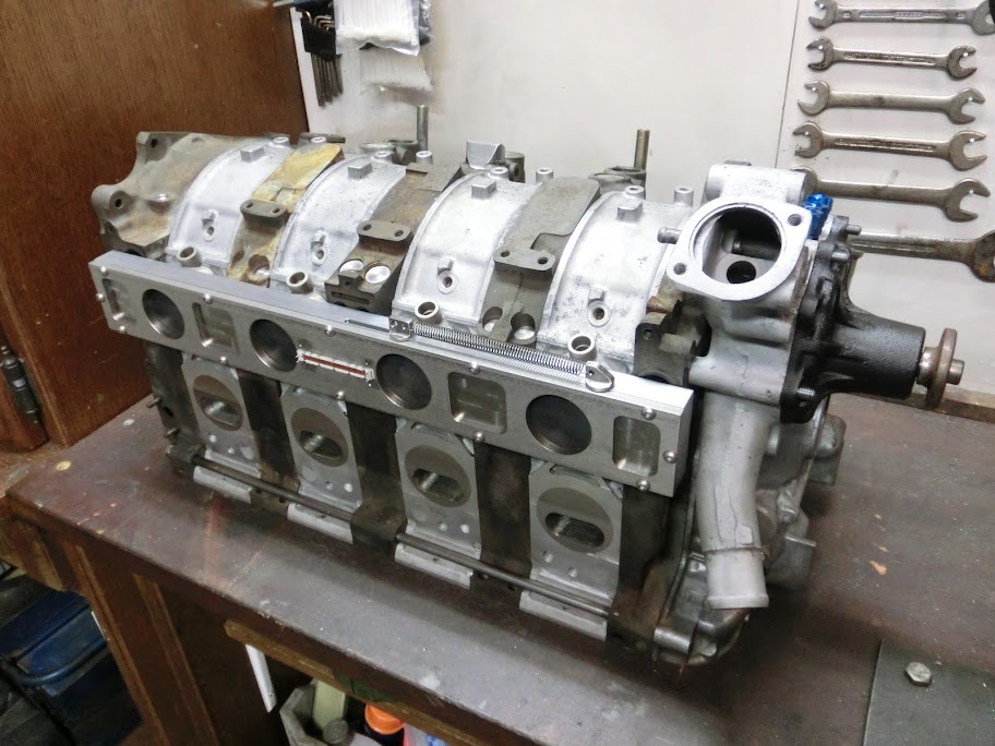
If I would do mine throttlebody again I would go with butterfly valves. For a normal 2-rotor engine with side ports I wouldn't even concider a slide throttle body, but do something like this instead:
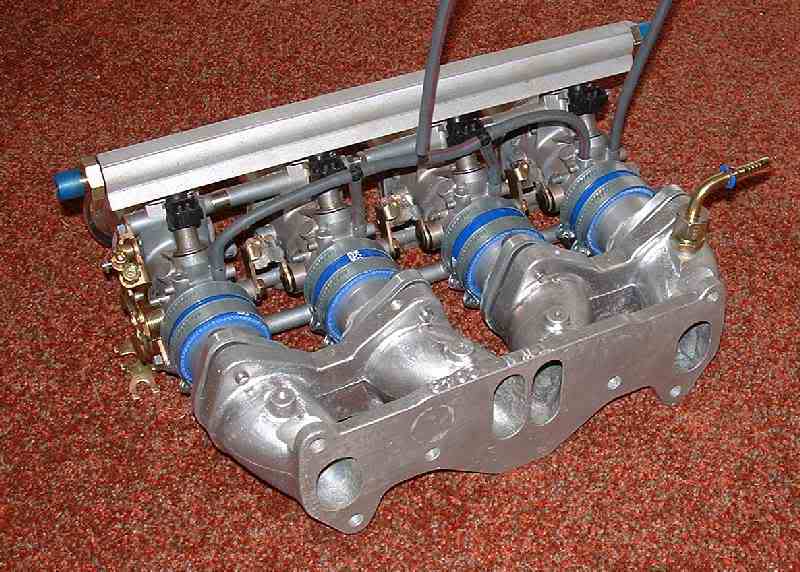
It's easier, cheaper, and in reality it works just as good as the slide throttles. Do not use one butterfly valve for both ports on the intermediate iron, that will cause bad mojo, it needs to be seperated. And I don't quite follow you on the injector location, you want them located in the intake port runner in the iron? That's how the stock setup is. People have succesfully just used 2 larger injectors in the oem primairy location and ditched the secondary injectors. If your going to fit motorcycle ITB's it might be an option to use the oem primairy injectors, and use the 4 motorcycle injectors as secondarys. Search around for the user 23racer on this forum, He's running a similar ITB setup on I believe a bridgeported 13B.
It's easier, cheaper, and in reality it works just as good as the slide throttles. Do not use one butterfly valve for both ports on the intermediate iron, that will cause bad mojo, it needs to be seperated. And I don't quite follow you on the injector location, you want them located in the intake port runner in the iron? That's how the stock setup is. People have succesfully just used 2 larger injectors in the oem primairy location and ditched the secondary injectors. If your going to fit motorcycle ITB's it might be an option to use the oem primairy injectors, and use the 4 motorcycle injectors as secondarys. Search around for the user 23racer on this forum, He's running a similar ITB setup on I believe a bridgeported 13B.
Thread Starter
Madman
Joined: Oct 2013
Posts: 25
Likes: 0
From: Lake of the Ozarks, Missouri
I know the slide is a pain, but butterflies still scare me due to the fact that I'll have space issues with them sticking straight out like that or I will end up with inefficient oddly shaped runners that are way too long. I'm not actually worried about the injectors, I just ramble when the gears start turning in my head. Right now all I really know for sure is that the intake must come around to the top of the engine. This is a turbo application so the space on the left side of the engine bay is limited. Intercooler piping will be ran around the front of the car and come up to the plenum above the engine like you see in most cars.
Thread Starter
Madman
Joined: Oct 2013
Posts: 25
Likes: 0
From: Lake of the Ozarks, Missouri
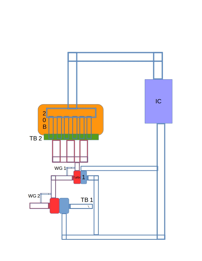
I'll spill... here's the plan a little dumbed down.
Compound/sequential twin turbo no blow off valves.
See I might need space, and I'm trying to make everything as compact and efficient as possible to reduce throttle/turbo lag. I'm not sure if it will lag a lot or be scary responsive.
Compound/sequential twin turbo no blow off valves.
See I might need space, and I'm trying to make everything as compact and efficient as possible to reduce throttle/turbo lag. I'm not sure if it will lag a lot or be scary responsive.
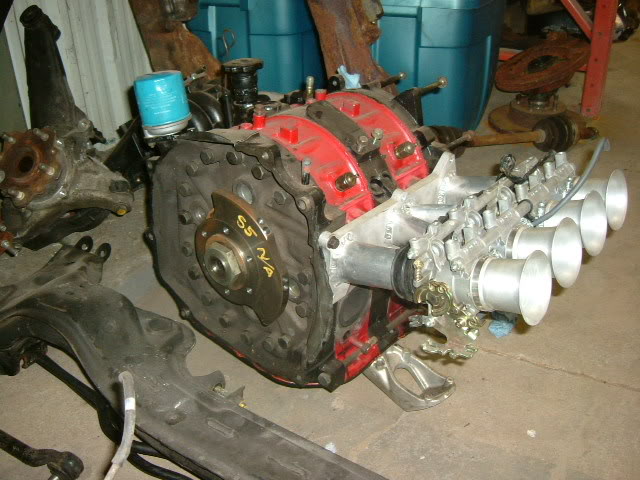
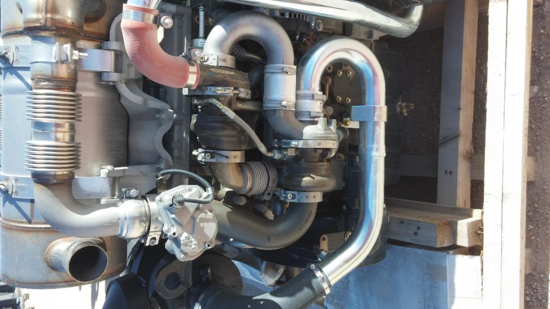
I've always been curious about doing something like this but turbos recently are becoming more and more efficient. Here's another example for you.
This is a diesel. In the pic, you can see the exhaust feeding the upper small turbo then onto the larger lower. The intake feeds the larger lower and then goes up to the upper smaller. I think this creates less lag since everything stays in series. It also eliminates the y pipe before IC (like in your drawing). Also, keep in mind that this configuration may not work on a rotary because once that big trouble comes online, the exhaust energy coming from the engine to the small turbo may overspeed the turbo in the upper rpm ranges (even with a wide open wastegate).
Edit: I cant stand sometimes uploading from my phone when it rotates like this.
Not shure if slide tb and boost is a good mix?
And if you use these tb's, they won't take up much more space than slide tb's.
48mm Universal ITB Throttle body D shaft : RHD Engineering
And if you use these tb's, they won't take up much more space than slide tb's.
48mm Universal ITB Throttle body D shaft : RHD Engineering
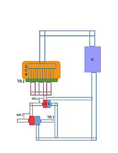
I'm confused by your turbo diagram. The hot sides look like a compound turbo setup, and the cold sides look like a sequential setup with the throttlebody placed in the wrong place. Are you trying to archieve a sequential setup to reduce lag or a compound setup to increase the pressure ratio?
The picture t-von posted is a more regular compound turbo setup, it's more commonly used on diesels so they can run a pressure ratio beyond the capability of a normal single turbo. So above 40psi of boost or so. It's very cool, but I forsee issues with a 20B and that amount of boost.
Turbo talk aside, I do think it's a good idea to incorporate ITB's, even on a turbo setup. That needs to be done more often! I still wouldn't use a slide throttle, maybe fabricate a short intake manifold that sweeps 120 degrees or so with a reasonably short radius, and incorporate 6 throttlebodies. M3 6-cyl throttlebodies come to mind, or 2 pairs of triumph 3-cyl throttlebodies. If you're able to machine nice stuff it might be possible to make a 20mm thick or so spacer that bolts onto the side of the iron (like my slide throttle), and incorporate a throttleshaft and butterfly valves into the spacer to create a really flat TB. I think I would to with the first option because it's easier.
Trending Topics
Thread Starter
Madman
Joined: Oct 2013
Posts: 25
Likes: 0
From: Lake of the Ozarks, Missouri
I'm confused by your turbo diagram. The hot sides look like a compound turbo setup, and the cold sides look like a sequential setup with the throttlebody placed in the wrong place. Are you trying to archieve a sequential setup to reduce lag or a compound setup to increase the pressure ratio?
The picture t-von posted is a more regular compound turbo setup, it's more commonly used on diesels so they can run a pressure ratio beyond the capability of a normal single turbo. So above 40psi of boost or so. It's very cool, but I forsee issues with a 20B and that amount of boost.
Turbo talk aside, I do think it's a good idea to incorporate ITB's, even on a turbo setup. That needs to be done more often! I still wouldn't use a slide throttle, maybe fabricate a short intake manifold that sweeps 120 degrees or so with a reasonably short radius, and incorporate 6 throttlebodies. M3 6-cyl throttlebodies come to mind, or 2 pairs of triumph 3-cyl throttlebodies. If you're able to machine nice stuff it might be possible to make a 20mm thick or so spacer that bolts onto the side of the iron (like my slide throttle), and incorporate a throttleshaft and butterfly valves into the spacer to create a really flat TB. I think I would to with the first option because it's easier.
The picture t-von posted is a more regular compound turbo setup, it's more commonly used on diesels so they can run a pressure ratio beyond the capability of a normal single turbo. So above 40psi of boost or so. It's very cool, but I forsee issues with a 20B and that amount of boost.
Turbo talk aside, I do think it's a good idea to incorporate ITB's, even on a turbo setup. That needs to be done more often! I still wouldn't use a slide throttle, maybe fabricate a short intake manifold that sweeps 120 degrees or so with a reasonably short radius, and incorporate 6 throttlebodies. M3 6-cyl throttlebodies come to mind, or 2 pairs of triumph 3-cyl throttlebodies. If you're able to machine nice stuff it might be possible to make a 20mm thick or so spacer that bolts onto the side of the iron (like my slide throttle), and incorporate a throttleshaft and butterfly valves into the spacer to create a really flat TB. I think I would to with the first option because it's easier.
As for throttle bodies, I don't think I can win. I'm trying to get the best geometry out of the intake piping and get the throttle plate as close to the engine as possible. I look under peoples hoods and cringe when the intake is a mangled mess and has so many bends it would make a great roller coaster. I probably will have a lot of bends, but I try to keep it short and the bends mellow, unless it has benefits like an increase velocity like from a throttle body spacer.
That is something I don't know. When is the space between the engine and throttle plate good and how much space is bad? How do you get the best velocity, fuel atomization, flow, and throttle response out of the space between the throttle plate and the engine? It sounds like a lot of work if you were to try and tune it, you would basically have to make a new manifold every time you moved the throttle body.
Not shure if slide tb and boost is a good mix?
And if you use these tb's, they won't take up much more space than slide tb's.
48mm Universal ITB Throttle body D shaft : RHD Engineering
And if you use these tb's, they won't take up much more space than slide tb's.
48mm Universal ITB Throttle body D shaft : RHD Engineering
Arrogant Wankeler


Joined: Nov 2006
Posts: 1,009
Likes: 233
From: Hunter Valley NSW Australia
The way the setup works is like the old F1 turbo cars back in the 80's. You've probably heard, but they ran no BOVs, but had a throttle plate before the turbo. When you let off the throttle the front throttle plate shuts and puts the turbo in a vacuum, so no dangerous compressor surge. Some people think it can suck out oil in the bearings on today's turbos, but I've heard otherwise even though those F1 cars were running space age carbon fiber seals or whatever I don't even know. Anyway, yes the hot side is compound and the cold is sequential. So, turbo 2 assists turbo 1 and when turbo 1 is at the top of it's powerband the wastegate (this might require 3 very large wastegates on each header pipe) bypasses it and turbo 2 gets full power. It's similar to an Opel twinturbo setup and I've seen some Supra guys do it... but they used about 70mm turbos and said it lagged like crazy. Getting the right size turbos is the hard part and keeping it from blowing the engine might also be an issue. I was planning on using methanol fuel, a good mix of oil in the gas tank, a super-cooled water-to-air intercooler, and possibly nitrous (if that helps and doesn't lean it out). I think it will be a nice adventure!
As for throttle bodies, I don't think I can win. I'm trying to get the best geometry out of the intake piping and get the throttle plate as close to the engine as possible. I look under peoples hoods and cringe when the intake is a mangled mess and has so many bends it would make a great roller coaster. I probably will have a lot of bends, but I try to keep it short and the bends mellow, unless it has benefits like an increase velocity like from a throttle body spacer.
That is something I don't know. When is the space between the engine and throttle plate good and how much space is bad? How do you get the best velocity, fuel atomization, flow, and throttle response out of the space between the throttle plate and the engine? It sounds like a lot of work if you were to try and tune it, you would basically have to make a new manifold every time you moved the throttle body.
Those butterfly valves look compact enough, could be doable, definitely a better option over a slide.
Thread Starter
Madman
Joined: Oct 2013
Posts: 25
Likes: 0
From: Lake of the Ozarks, Missouri
I suspect you will find it difficult to tune the transition well (VE will be wonky probably best to tune fuel with EMP modifier, as will required turbine flow- whatever table you use for the primary gates) and lose out on peak system efficiency doing it that way. Potential to overspeed the small turbo also. I'm assuming you want to run something like 50-80PSI boost to bother with this, if you just want better response and a lower boost threshold with a large power turbo, I'd run either conventional compound/series turbo (better final efficiency due to compressor and turbine power balance across stages) or series charged with a positive displacement supercharger running at ~135% theoretical engine displacement and you will have instant response and better final efficiency (at decent boost ~35-50PSI) than a single stage turbo compressor being fed power by a turbine with a redundant exhaust manifold blockage in the way (the smaller turbo and gates) will have in the top end. The super-turbo will be the most consistent for mapping purposes.
to create a lot of power, fast. I expect it to be very jumpy and unstable, very difficult to handle. It's also risky, very high stress. For one, it could easily create too much boost for the engine, also the turbos will be under immense load. Both will spin at high speed most of the time, the smaller turbo can be oversped, and I'm not sure how they will react with a throttle body upstream of them.
It's basically because of all this that I'm so interested in the setup. It's a challenge and a good experience. The more I work on the tuning the more I can perfect it so it can go safely down the road, that's my goal so I can see exactly how it performs, I would also like to see an increase in gas mileage if it doesn't need a fire truck to feed it fuel to keep the afr normal.

Full Member
Joined: Nov 2011
Posts: 105
Likes: 0
From: orange, ca
The way the setup works is like the old F1 turbo cars back in the 80's. You've probably heard, but they ran no BOVs, but had a throttle plate before the turbo. When you let off the throttle the front throttle plate shuts and puts the turbo in a vacuum, so no dangerous compressor surge. Some people think it can suck out oil in the bearings on today's turbos, but I've heard otherwise even though those F1 cars were running space age carbon fiber seals or whatever I don't even know. Anyway, yes the hot side is compound and the cold is sequential. So, turbo 2 assists turbo 1 and when turbo 1 is at the top of it's powerband the wastegate (this might require 3 very large wastegates on each header pipe) bypasses it and turbo 2 gets full power. It's similar to an Opel twinturbo setup and I've seen some Supra guys do it... but they used about 70mm turbos and said it lagged like crazy. Getting the right size turbos is the hard part and keeping it from blowing the engine might also be an issue. I was planning on using methanol fuel, a good mix of oil in the gas tank, a super-cooled water-to-air intercooler, and possibly nitrous (if that helps and doesn't lean it out). I think it will be a nice adventure!
As for throttle bodies, I don't think I can win. I'm trying to get the best geometry out of the intake piping and get the throttle plate as close to the engine as possible. I look under peoples hoods and cringe when the intake is a mangled mess and has so many bends it would make a great roller coaster. I probably will have a lot of bends, but I try to keep it short and the bends mellow, unless it has benefits like an increase velocity like from a throttle body spacer.
That is something I don't know. When is the space between the engine and throttle plate good and how much space is bad? How do you get the best velocity, fuel atomization, flow, and throttle response out of the space between the throttle plate and the engine? It sounds like a lot of work if you were to try and tune it, you would basically have to make a new manifold every time you moved the throttle body.
Those butterfly valves look compact enough, could be doable, definitely a better option over a slide.
As for throttle bodies, I don't think I can win. I'm trying to get the best geometry out of the intake piping and get the throttle plate as close to the engine as possible. I look under peoples hoods and cringe when the intake is a mangled mess and has so many bends it would make a great roller coaster. I probably will have a lot of bends, but I try to keep it short and the bends mellow, unless it has benefits like an increase velocity like from a throttle body spacer.
That is something I don't know. When is the space between the engine and throttle plate good and how much space is bad? How do you get the best velocity, fuel atomization, flow, and throttle response out of the space between the throttle plate and the engine? It sounds like a lot of work if you were to try and tune it, you would basically have to make a new manifold every time you moved the throttle body.
Those butterfly valves look compact enough, could be doable, definitely a better option over a slide.

Thread
Thread Starter
Forum
Replies
Last Post
Turblown
Vendor Classifieds
12
Oct 17, 2020 03:25 PM
Snook
3rd Generation Specific (1993-2002)
23
Sep 30, 2015 11:36 AM