
Power FC Troubleshooting Sensors Need Help

Troubleshooting Sensors Need Help
Okay I've completed my single turbo conversion and have narrowed down/fixed alot of bugs I had, now just need to deflood engine and fix this annoyance:
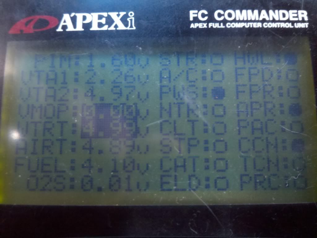
Check the sensors via the commander and is showing my IAT and water temp are way outta range. I checked and rechecked the harness, connectors and ground points. (grounded both to engine block) and cant seem to find the problem. I have the following mods; A single turbo harness, Fast reacting IAT, omp delete,All emmisions removed, Rewired remote fuel pump.
Does the fast reacting AIT need to be calibrated with PFC
All suggestions are welcome and TIA.


Have you backprobed the wires on the ECU plug(s) to see if the voltage agrees?
The fast acting IAT does not require a calibration change, but you couldn't change the calibration if you wanted to because it's not possible with the software. The calibration also wouldn't affect the voltage reading, just the way that the computer interprets the voltage.
The fast acting IAT does not require a calibration change, but you couldn't change the calibration if you wanted to because it's not possible with the software. The calibration also wouldn't affect the voltage reading, just the way that the computer interprets the voltage.

Joined: Mar 2001
Posts: 31,857
Likes: 3,243
From: https://www2.mazda.com/en/100th/
5v for the water temp suggests a short. have you checked the water temp sensor? i have seen them short before.
actually i saw one that intermittantly was shorting or was just open, so the ecu either thought it was
-32F or +300F, and basically either way the car wont run.
-32 = severe flooding
super hot = not enough fuel to start the car
actually i saw one that intermittantly was shorting or was just open, so the ecu either thought it was
-32F or +300F, and basically either way the car wont run.
-32 = severe flooding
super hot = not enough fuel to start the car
Oh bother so this was def "one" of the many issues why I couldnt get the car started. Ok I def need to check the ECU/harness side of the connectors but being that its more than one def sounds like a harness issue or sumtin
Would a faulty or missing ground cause this?
I have one ground bolted directly to the engine block and I have my Fuel pressure sender unit bolted on a Al bracket near it.
Do all these sensor share a common ground?
Im just thinking for both well actually 3 sensors to be out of range makes me believe something is not grounded or plugged. I do have a single black connector in the passenger footwell that I cant find a connection for.
oh and the reason I say 3 is beacuse the VTA2 is outta wack as well, isnt it?
Yeah readthrough the fsm and it said the same thing short or open circuit so read through some definitions and then checked the harness side of connectors and I indeed have a open circuit well at least up to te harness side of sensors.
I will probe at the ECU connector side tomorrow.
If I recall isnt all the connectors on the backside of ECU different sizes?
Could a faulty ground be the culprit?
WTH are the blue and white connectors for? I have them connected but their are two of each in the passenger dash...WTH!?!?!
Offtopic: Hey CW I have your pm jus trying to get these kinks ironed out and car started before I even think about tuning
Trending Topics
So reading through the FSM wirig diagram it looks like the IAT, ECT, and TPS all share the same BR/B color wire which runs into the ECU at pin 4D so going to check that pin and wire.
Is this a ground wire they share?
Is this a ground wire they share?
OK WTF the CTS crumbled on me upon removal and the ground wire coming from the back of the IAT sensor is B/W according to FSM its suppose to be BR/B. Is this the culprit? and if so can I simply splice the wire back into the BR/B wire in the engine harness?
also the reading on the BR/B wire from the ecu is 0.01 this ok for the wire?
also the reading on the BR/B wire from the ecu is 0.01 this ok for the wire?
The AWS connector is B/W & BR/Y, are you sure you haven't got those mixed up? They are close to each other.
When you say you have a single turbo harness, is this something you bought or stripped down yourself?
Edit: B/W is 12V power to most of the solenoids. Something is messed up, the IAT never sees 12V, so you have probably fried that, you need to hope that you have not been backfeeding voltage in to the PFC grounds. This can cook the PFC also.
Last edited by Banzai-Racing; Mar 7, 2011 at 04:23 PM.
Bingo!! yeah I checked the voltage on the connectors to the IAT sensor and the B/W was reading 10.8 V and the green wire wasnt reading anything...so ok all this makes sense now thank you! As far as the harness goes bought it (barely used) from forum member Allrotor. Damn well I dont think (I hope to god) I fried the ecu as I checked all other sensor connectors that share the Br/B wire (CST & TPS) and they checked fine on both the power wire and nothing on the Br/B Grd wire.
Damn this sucks, so can I simply cut and splice the IAT sensor wires correctly back into the harness?
Hope to god the ECU is not fried, if so someone is going to have to reimburse me and refund me my money on the harness or supply me with a new one.
Oh and no AWS
Damn this sucks, so can I simply cut and splice the IAT sensor wires correctly back into the harness?
Hope to god the ECU is not fried, if so someone is going to have to reimburse me and refund me my money on the harness or supply me with a new one.
Oh and no AWS
Ok so the conclusion....Whomever simplified this harness cut off the actual IAT pigtail and left the Purge solenoid valve in its place B/W & G/Y (thinking it was the IAT connector).
The IAT and the solenoids have the same stlye connectors. I checked the 4D and 3L pins for the IAT sensor and they are still intact (on ecu side) and the solid green wire when I backprobed has voltage.
So can I jus splice or tap into both wires at the ECU connector and run them "in correct orientation" to the IAT sensor?
You can try to rewire it, but it sounds like whoever did the mods to it made some errors. I am not sure I would trust it, since your VTA2 on the TPS is showing max voltage also. The last thing you want is a cluge of wires running through the engine bay all the back to the ECU just to fix a problem caused by someone else.

Thread
Thread Starter
Forum
Replies
Last Post
rotor_veux
2nd Generation Specific (1986-1992)
7
Sep 19, 2015 07:13 PM
acting, calibration, ecu, electromotive, fast, iat, install, intake, microtech, pfc, reading, sensor, sensors, temperature, troubleshooting, working